Baselier FA W Series Installation and operation manual

Bronkhorststraat 5 ■ 4651 SZ Steenbergen ■ The Netherlands
CULTIVATOR POTATO PLANTER
TYPE FA –(B)W
OPERATOR’S MANUAL & PARTS LIST
2020

FA-(B)W –EN 2
CONTENTS BASELIER
1. Introduction 3
2. Warranty and installation 4
3. Safety 5
Safety labels explained and position on the machine 8
4. Checks before operation 10
5. Mounting on tractor 11
Notes 14
6. Spare parts and technical details 15
7. Operation 16
Planting distance mechanically driven planting elements 20
8. Check daily 21
Check weekly –Problems and solutions 22
9. Winter storage 23
10.Maintenance –Checklist 24
11.Instructions for moving the machine 25
12.Part numbers cultivator potato planter:
-Group 1 Drive line rotor shaft 26
-Group 2 Depth wheels + safety parts 28
-Group 3Full width plate, ridging hood + track wipers 30
-Group 4Hopper, planting elements + ridging discs 32
-Group 5Sirius planting element 34
-Group 6Marathon planting element 36
-Group 7Mechanical drive planting elements part 1 38
-Group 8 Mechanical drive planting elements part 2 40
-Group 9 Marker manual and hydraulic 42
-Group 10 Drive line rotor shaft FA-BW 44
13.Hydraulic depth control 46
14.Hydraulic ridging hood adjustment 47
15.Labels and safety labels –Accessories 49
16.EG-Statement of agreement for machines 50

FA-(B)W –EN 3
1. INTRODUCTION
Take your time to read this operator’s manual.
Because this machine is used in combination with the tractor, also read the operator’s manual
of the tractor.
This manual enables you, as the owner/operator, to obtain maximum productivity from your
BASELIER CULTIVATOR POTATO PLANTER.
The considerable variation of soils make it difficult to be specific, but the use of this manual
along with the operator’s ability to handle machines of all model/types, means little difficulty will
arise.
In order to get the best results from your machine and keep it in good condition, it is important
to read and follow the instructions with regard to control, safety and maintenance. Do this
before you start to work with the machine, because then it will be too late.
This manual should be regarded as part of the machine. Vendors of both new and second hand
machines should have written evidence that this manual was provided with the machine.
The BASELIER CULTIVATOR POTATO PLANTER is designed for the following
operations in one single pass:
-cultivating the soil
-to plant potatoes
-forming ridges
Operation for other purposes will be considered as improper use, unless approved by the
manufacturer.
Compliance with and strict adherence to the conditions of operation, service and repair
as specified by the manufacturer, are also part of the proper use of the machine.
BASELIER reserves the right to make changes in specifications and maintenance requirements
at any time without notice as part of our tactfully continuous development and improvement.
In case there are still questions after reading this manual, we would appreciate hearing them
from you.
THIS MACHINE MEETS THE CE STANDARD.
USE ORIGINAL BASELIER PARTS ONLY.
YOU NOW POSSES AN EXCELLENT MACHINE, SO TAKE YOUR TIME TO PERFORM
EXCELLENT CULTIVATING AND POTATO PLANTING WORK AS WELL.

FA-(B)W –EN 4
2. WARRANTY AND INSTALLATION
Although every care has been taken with respect to the choice of materials and components,
BASELIER can never be held responsible for damage to the machine o to third-party as a
result of improper use.
Dealers are being requested to follow a certain procedure before delivering a new machine.
This means a complete inspection before delivery to be sure the machine meets the operation-
and maintenance principles. All persons involved in the maintenance and operation of the
machine should be present during this instruction.
This machine can only be operated, maintained and repaired by persons who are familiar
with it and who know the safety-procedures.
Operators who require further assistance with operating instructions or maintenance of the
BASELIER CULTIVATOR POTATO PLANTER, should consult their dealer or:
BASELIER Tel : +31(0)167-564464
4651 SZ STEENBERGEN www.baselier.com
The Netherlands
BASELIER is always striving after perfection of its products and reserves the right to
introduce modifications, without any obligation with respect for previously delivered
machines.
Note:
Every reference to left or right is made from the position behind the machine seen in driving
direction of the tractor.
LEFT
FRONT
FRONT
RIGHT
REAR
REAR

FA-(B)W –EN 5
3. SAFETY!
Follow all safety-rules including the instructions in the manual and the safety labels on the
machine.
Because this machine is used in combination with the tractor, also read the operator’s manual
of the tractor.
The installed safety-equipment like:
- protection cover PTO shaft and planting elements page 7-9-28-29
- protection rails on both sides and 4 support legs page 7-28-29
- safety labels explained and position on the machine page 8-9
should under no circumstances be removed and should in case of damage be repaired
or replaced immediately.
The protection of the PTO shafts should be secured with small chains to the protection covers
to prevent them from turning.
Ensure proper protection of the clutch shafts. Replace protections by damages directly.
Never carry out repairs or adjustments or leave the tractor unless gear lever is in neutral,
brakes on, and engine switched off with ignition key removed.
The machine should be in lowest position on the ground on 4 support legs and firmly
supported.
Always use a tractor with a cab.
Consult the manual of the tractor with respect to coupling and safe operation.
Declutch and shift into neutral before starting the engine of the tractor.
Through the high speed of the PTO shaft and rotor shaft, and non-compliance or
enforcement of safety rules the machine can be a dangerous machine.
NEVER LIFT THE MACHINE WHEN THE ROTOR SHAFT IS RUNNING!
Follow this procedure: 1) switch off PTO shaft tractor
2) wait until the rotor shaft completely stopped turning
3) lift the machine with the 3 point linkage
This machine should only be operated by experienced and careful persons who know
the machine, who have read the manual and therefore know the instructions and safety-
rules.
By transport on public roads, take care of the local and general regulations like: lightning,
reflectors, length and width of warning signs.
By transport on public roads or while working in the land there should be no persons or loose
parts on the machine.

FA-(B)W –EN 6
NEVER adjust the top link during cultivating and potato planting because there is danger of
falling between the tractor and the rotating shaft or to be clamped (page 8).
Make sure that, while working with the machine, nobody is in the danger zone.
If necessary you should warn them to keep a safe distance.
- keep a minimal of 5 meters distance at the sides of the machine
- keep a minimal of 20 meters distance at the front and rear side when the rotor shaft is running.
Make sure that the working area is free from foreign objects and stones.
Make sure that the soil of the working area is levelled.
In case the machine should hit an obstacle, stop the machine immediately and check on
damages before going on.
Avoid working in a field where there is a risk of overturning of the tractor.
Obey the safety rules while driving, like lowering speed in case of hangs or sharp bends.
Look out for hidden obstacles and pay attention to the transport width of the machine.

7
FA-(B)W –EN 8
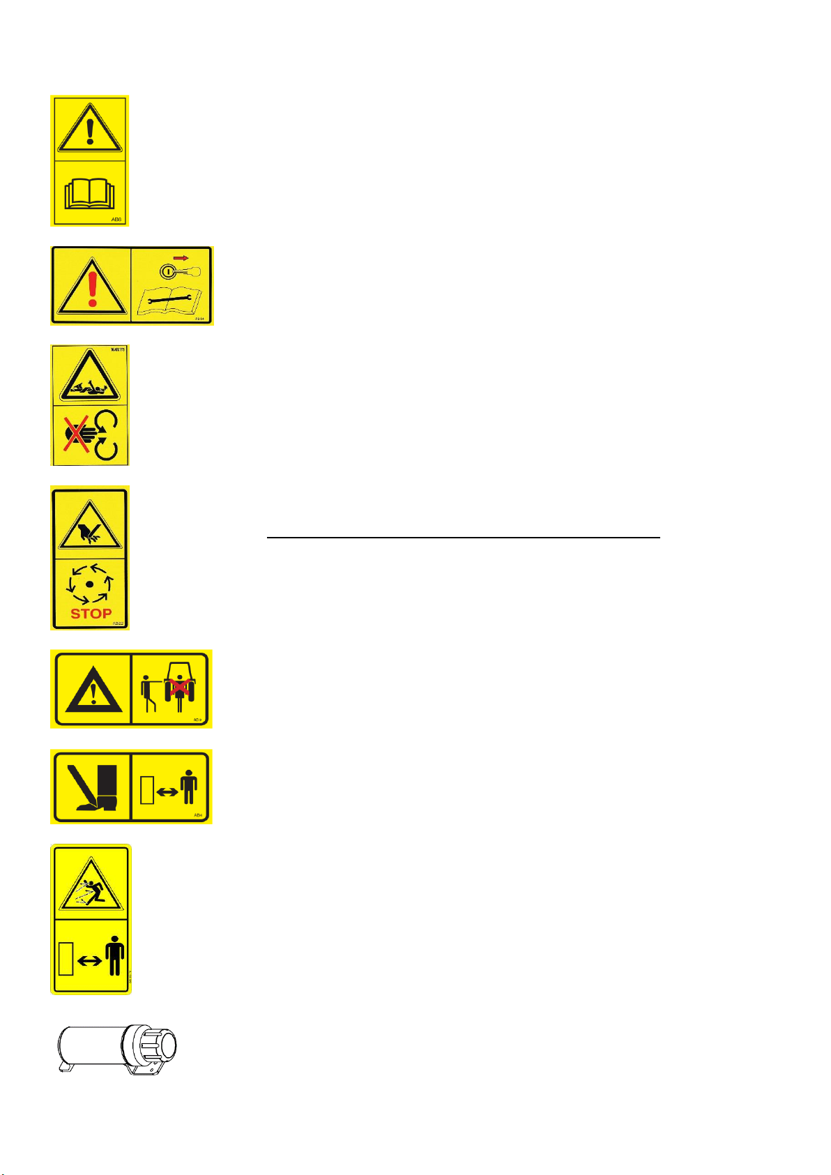
SAFETY LABELS EXPLAINED
1.
Attention!
Read instruction book before operating or performing
maintenance on the machine.
Read also the safety instructions before using the machine.
2.
Attention!
Stop tractor, remove ignition key and read instructions before
carrying out any maintenance, cleaning or servicing.
3.
Attention!
Stay clear to the PTO shaft when the tractor engine is running.
The rotating parts can grab clothing, hands, hair etc. and sweep away
with serious consequences.
Replace protections in case of damage directly.
4.
Attention!
Danger when the rotor shaft is running.
Stay away with hands when the rotor shaft is running.
Follow this procedure:
1. Switch off PTO shaft from tractor.
2. Wait until the rotor shaft complely stopped.
3. Lift the machine with the 3 point linkage.
5.
Attention!
Stay clear of 3 point linkage when the machine is running.
Between the tractor and machine there is danger for personal
injury.
Don’t operate the 3 point linkage between the tractor and machine.
6.
Attention!
Stay clear of at least 5 meter on both sides of a working or lower
down machine to the ground.
Do not attempt any adjustments when the machine is running.
7.
Attention!
Danger of flying around of stones or clods.
Keep onlookers and bystanders at a safe distance from the
machine while it is in operation.
Keep minimal 20 meters distance at the front and rear side of the
machine when the rotor shaft is running.
This count especially when starting the ridge building.
8.
Document holder instruction manual
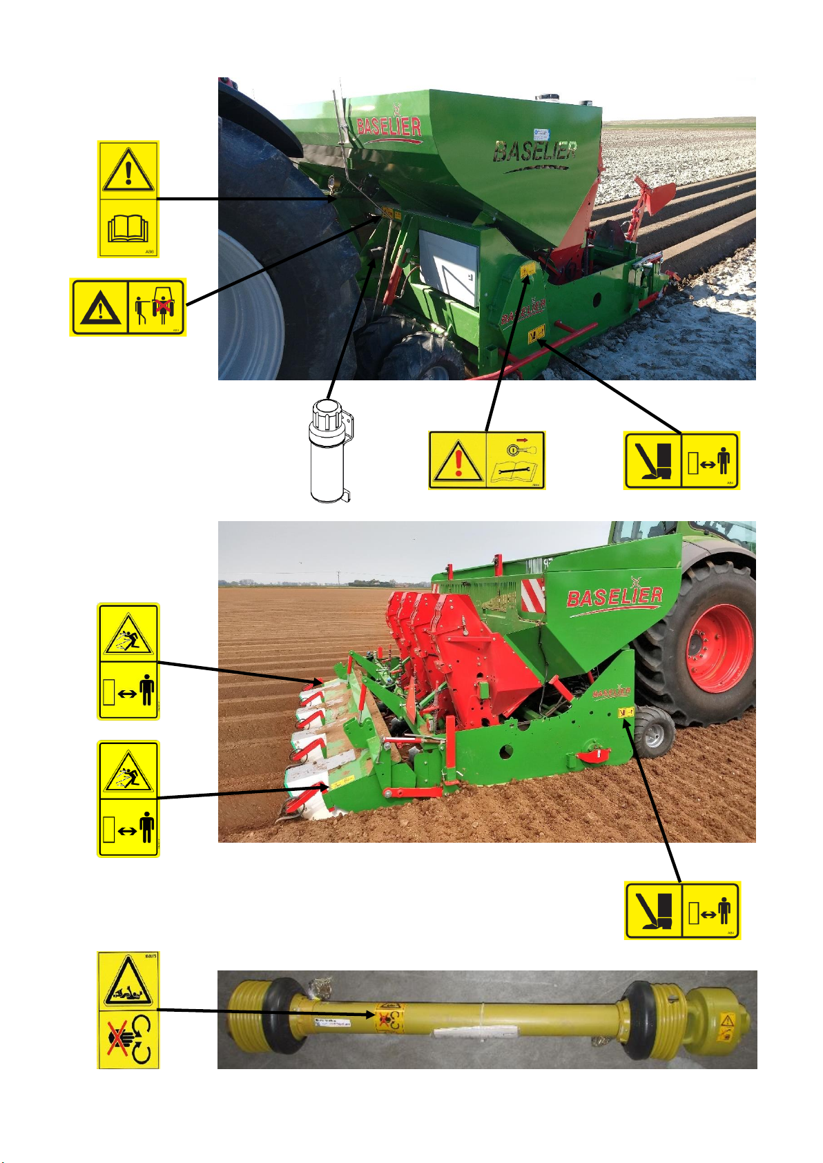
FA-(B)W –EN 9
POSITION OF THE SAFETY LABELS ON THE MACHINE

FA-(B)W –EN 10
4. CHECKS BEFORE OPERATION
-Check if all protection covers, -clamps etc. are mounted well (see page 7).
-Check the oil level of the gearbox.
Before checking, you must open the plugs of the gearbox and chain guard and clearing
them from soil or other dirt.
Remove the plugs with fitting tools.
After checking lightly grease the screw-thread of the plugs, and reassemble.
-Check the grease-level of the chain-guard (see page 21-22).
-Check the chain tension (see page 21-22).
•4 grease points PTO shaft (2x PTO shaft pipe + 2x cross PTO shaft).
•4 grease points bearings axles depth wheels (page 24).
•1 grease point conical bearing top shaft gearbox (at chain guard page 24).
•1 grease point bearing rotor shaft (page 24).
•2 grease point depth adjustment full width plate with furrow opener (page 24).
•8 grease points ridging discs.
•4 grease points PTO shaft and 2 grease points bearing top shaft (only FA 310-380BW)
(see page 44, part number 8, 9 and 33)
Grease the universal joint and the sliding parts of the PTO shaft (see drawing).
Make sure the PTO shaft can be moved in and out.
Mount the PTO shaft and mount the safety chains on the protection cover of the machine and
the tractor.
To ensure a long life of the PTO shaft, the angles it should operate, should not be more than 15
degrees.

FA-(B)W –EN 11
5. MOUNTING ON TRACTOR
A. For mounting on the tractor see also the operator’s manual of the tractor.
The machine is provided with a 3 point linkage for Cat III.
The machine should be mounted on a flat surface.
Mount the lever arms on the machine. After that mount the top link.
Ensure that the hydraulic system is pressureless and the tractor engine is switched off.
Connect the hydraulic tubes to the tractor.
Mount the PTO shaft on the tractor.
Connect the plug for the lighting to the tractor.
Put the lever arms of the tractor in one of the 2 holes A.
Always connect the machine as short as possible to the tractor but make sure that the
depth wheels or hopper of the machine don’t hit the tractor when the machine is lifted up.
Mount the top link of the tractor in top link plate B.
Check if the locking pins of the top link pin and draw pins of the 3 point linkage Cat III are
mounted well.
Use the stabilization chains or stabilizer bars to prevent the machine turn over sideways
and make sure that the machine is exactly in the middle. A range of approx. 2 cm to the left
and right is allowed.
When the PTO shaft of the tractor is
disconnected, the PTO shaft must hang in
the bracket (see drawing C).
When the PTO shaft is connected to the
tractor the PTO bracket must be in the
horizontal position (see drawing D).
Before disconnecting the hydraulic tubes,
ensure the hydraulic system of the tractor
is pressureless.
Place the hydraulic tubes in bracket E.
E
A
B
C
D

FA-(B)W –EN 12
B. Preferably use an implement on the front side of the tractor which equalizes the soil.
This will improve the stability of the tractor and the implement serves as a front weight.
If an implement is not available, place front weights on the front side of the tractor.
As a result the tractor remains well stable at transport on the road or at the field.
C. Levelling:
-Lift the cultivator potato planter and check if the machine is levelled to the flat surface
on the left and right side.
-If needed adjust the lever arms of the tractor.
-Make the lever arms as short as possible.
-Make sure the tire pressure of the tractor is equal on both sides.
This will make sure that the working depth will be equal and it realizes a large lift.
Never lift the machine higher than 40 cm off the ground.
Always make sure the rear window of the tractor is closed when using the machine
especially when the machine is lifted up!

FA-(B)W –EN 13
D. Adjust the lowering speed of the machine with the 3 point linkage to slow when the machine
goes down.
This gives you time to smoothly switch on the PTO of the tractor while the machine is
gradually sinking into the ground.
The speed of the PTO shaft from tractor to gearbox should be 1000 RPM.
E. When you fix the PTO shaft for the first time, the correct length of the PTO shaft should be
checked carefully. After that, continue as follows:
F1
Pull the PTO shaft apart and fix one half of the shaft to the gearbox of the machine and the
other half to the PTO shaft of the tractor.
To adjust the length, hold the half-shafts next to each other in the shortest working position and
mark them. The outer protection tube should be at least 4 cm from the protection cover. Put the
3 point linkage in highest and then in lowest position and check, by holding both shaft halves
next to each other, if the overlap is at least 30 cm.
F2
Shorten inner and outer protection cover tubes equally.
F3
Shorten inner and outer sliding profiles by the same length as protection cover tubes.
F4
Round off all sharp edges and remove burrs from the sliding profile to prevent serious damage
and wear. Grease sliding profiles.
Check if the PTO shaft can slide well in and out.
Mount the PTO shaft and mount the safety chains to the protection cover of the machine and
tractor.
To ensure long life time of the PTO shaft, it is desirable that the angles are as small as possible.
Preferably not more than 15 degrees.
REPEAT THIS PROCEDURE WHEN USING ANOTHER TRACTOR!

FA-(B)W –EN 14
NOTES

FA-(B)W –EN 15
6. SPARE PARTS AND TECHNICAL DETAILS
When ordering spare parts indicate the model/type and number of the machine.
This information is mentioned on the aluminum plate at the top of the 3 point linkage and in the
frame.
Fill in below the model/type and number of your machine.
For next spare parts and orders you have the numbers hold by the hand.
TECHNICAL DETAILS CULTIVATOR POTATO PLANTER TYPE FA-W
TYPE
FA310W
FAE310W
FA330W
FA350W
FA380W
FA380BW
Working width
cm
305
305
325
345
365
365
Hook tines
amount
100
120
108
114
120
112 spikes
Hopper capacity
kg
2500
2500
2700
2900
3100
3100
Weight empty
kg
3100
3150
3250
3400
3500
3900
3 point linkage
CAT. 3
CAT. 3
CAT. 3
CAT. 3
CAT. 3
CAT. 3
Max. power
pk-kW
260-191
260-191
260-191
260-191
260-191
260-191
PTO shaft
RPM
1000
1000
1000
1000
1000
1000
Rotor shaft
RPM
450
450
450
450
450
450
Width
Length
Heigth
cm
cm
cm
340
350
200
340
350
200
340
370
200
340
390
200
340
410
200
340
410
200
Illustration, dimensions and weights may be altered without prior notice.
BASELIER AGRI TECH
STEENBERGEN-HOLLAND
MODEL
TYPE
No.
WEIGHT KG
YEAR
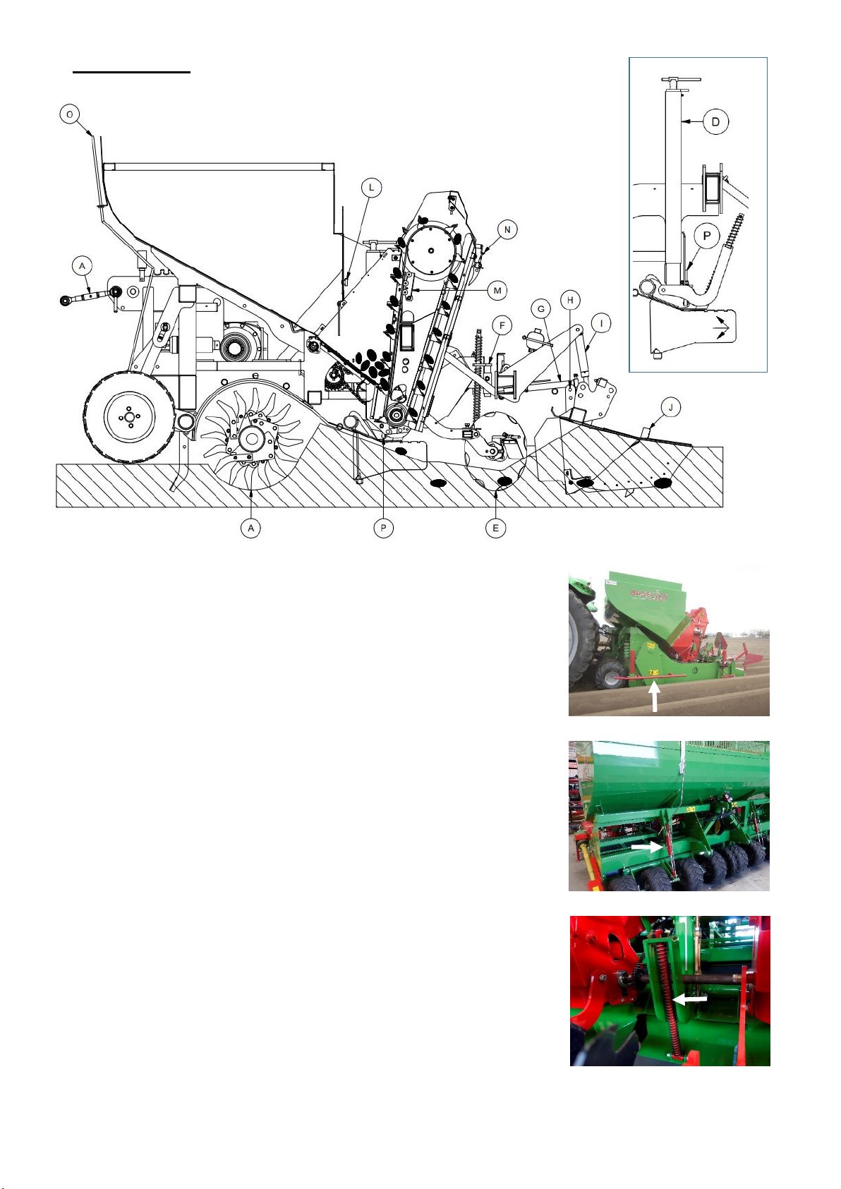
FA-(B)W –EN 16
7. OPERATION
A. Adjust the length of the top link Aof the tractor in such way, the
red protection bracket on the side of the machine are
horizontally (equal to the ground) when the machine is at
working depth. Connect the machine always as short as
possible to the tractor but make sure the depth wheels or
hopper can’t hit the tractor when the machine is lifted up, see
page 12.
B. The working depth of the hook tines is determined by the 9
depth wheels of the machine. The hydraulic system has 2
connections to the tractor, 2 press/retour pipes (page 44-45).
The hook tines are at maximum working depth when the
hydraulic cylinders are fully in. By moving the hydraulic
cylinders out, the working depth of the hook tines will decrease.
The position of the depth wheels can be checked by the
marking plates Oon the hopper.
C. The spring pressure Cof the full width plate ensures an even
distribution of the soil.
C

FA-(B)W –EN 17
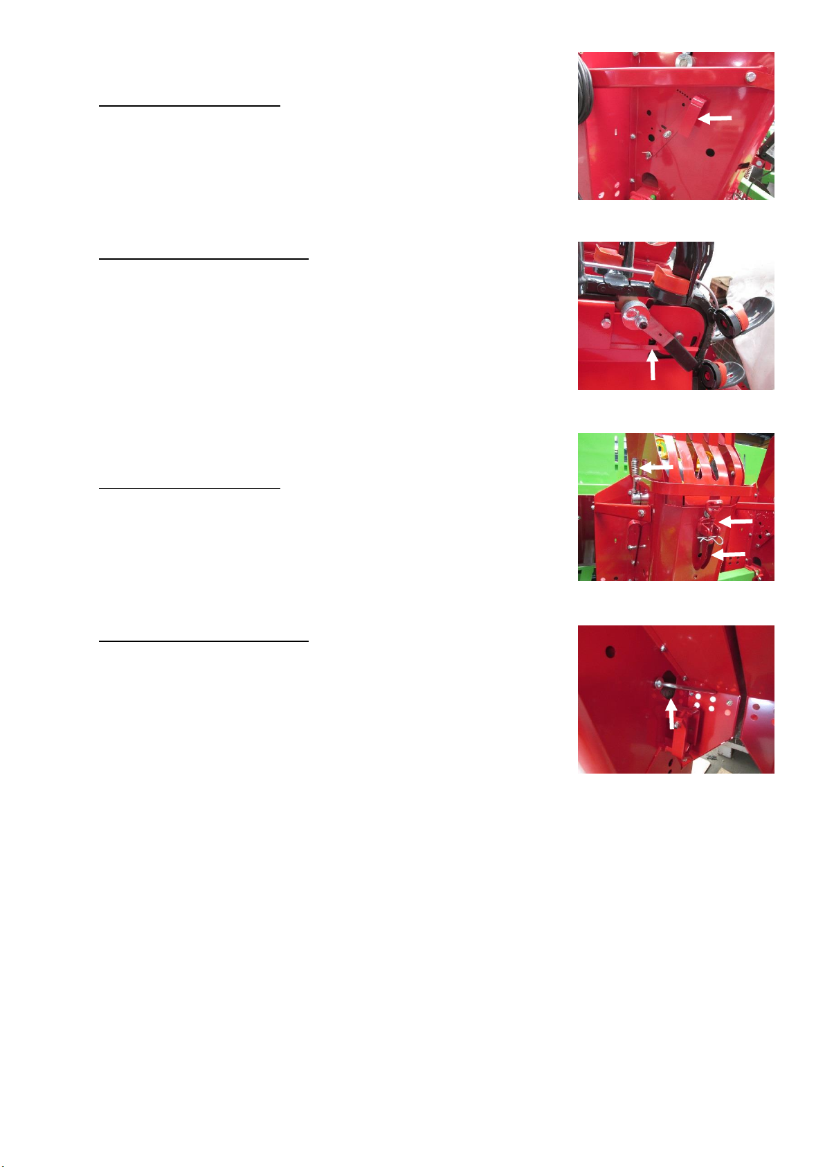
D. With spindle Dthe planting depth
is set. Make sure the spindles are
equal, see depth reading at the
bottom near spindle P. The angular
adjustment of the furrow openers
can be set by spindle P.
E. The ridging discs are adjustable in angle. Adjust the angle of
the ridging discs in such way, the soil can fluently flow through
the ridging hood. At light soils the scrapers should be
diagonally up. At heavy soils the scrapers should be set
vertically. The ridging discs are also adjustable in width. To
adjust the width of the ridging discs unscrew the bolt in the
middle and slide the ridging discs inwards or outwards.
F. When there is too little soil available in order to build a nice
row, the spring pressure on the ridging discs need to be
increased.
In that case you place the split pin in the upper hole. When
there is too much soil in front of the ridging hood, the spring
pressure on the ridging discs needs to be decreased.
In that case you place the split pin in the lower hole.
G. The height Xof the rows is adjustable by screwing the spindles
on both sides of the machine in or out.
When the spindles are screwed out, the height of the row
decreases.
H. Set the hydraulic pressure on the ridging hood at maximal 40
bar when the machine is working.
Decrease the hydraulic pressure when the rows are too firm.
When the hydraulic pressure is higher than 40 bar in working
position, the top link of the tractor should be shortened.
I. As an extra accessory, it is possible to mount spring tines
between the ridges, see page 30.
The ridging hood has 5 spring tines to break up the soil
between the rows.
You can set the working depth of the spring tines with the bolt
on the side at maximum 5 cm working depth.
D
P
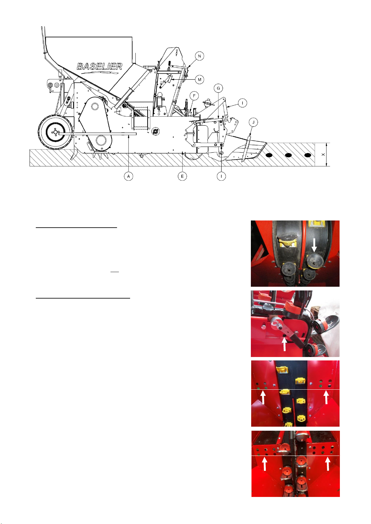
FA-(B)W –EN 18
J. Insert cups.
Sirius planting elements:
Depending on the size of the seed potatoes, the cups should
be provided with insert cups:
•Size 25/28 mm →white insert cups
•Size 28/35 mm →light green insert cups
•Size 35/55 mm →no insert cups
•Size above 55 mm →black insert cups
Marathon planting elements:
Depending on the size of the seed potatoes, the scoops should
be provided with insert cups:
•Size 25/28 mm →blue insert cups
•Size 35/55 mm →red insert cups (standard)
•Size above 55 mm →grey insert cups
K. The dosage plates of the hopper are adjustable in height.
For small seed potatoes set the dosing slides lower.
For large seed potatoes set the dosing slides higher.
Don’t set the dosage plates too high because it will damage the
seed potatoes and to reduce the chance of double seed
potatoes.
The seed potatoes at the cup belt (Sirius) and cup chain
(Marathon) may not be higher than the holes, see pictures on
the right.
FA-(B)W –EN 19
L. Vibration intensity cup band (Sirius) and cup chain (Marathon).
Sirius planting elements:
The intensity of the vibrator is adjustable by a lever to increase
or decrease the intensity.
Adjust the intensity so that doubles just fall out.
Don’t set the intensity unnecessarily high.
This will give damage to the seed potatoes.
Marathon planting elements:
The intensity of the vibrator is adjustable using the lever on the
top of the cup chain.
Adjust the intensity so that doubles just fall out.
Adjust the intensity unnecessarily high.
This will give damage to the seed potatoes.
M. Tension cup chain (Sirius) and cup chain (Marathon).
Sirius planting elements:
The tension on the cup band can be adjusted by screwing the
nut in or out. Screw in for more tension, screw out for less
tension. For a proper tension on the cup chain the compression
springs on both sides of the planting elements should have a
length of 45 mm. To take away the tension on the cup band
pull the lever up.
Marathon planting elements:
The tension on the cup chain is automatically regulated by a
number of compression springs. To take away the tension on
the cup chain pull the lever up.
1. At the first use of the machine it is advisable to do some settings without planting potatoes.
Before you start planting potatoes you can set the working depth, full width plate, plate with
furrow openers, ridging discs and ridging hood (this makes adjustments during potato
planting easier because you have adjusted the machine already partially).
2. After that you can fill up the machine with seed potatoes to start planting potatoes.
Check if the right insert cups are fitted and set the vibration intensity of the vibrators.
Check the correct planting distance on page 20.
3. Then cultivate and plant potatoes for a distance of about 10 meters.
Check the crumbling of the soil, the planting depth, the functioning of the planting elements,
the planting distance and the ridge building.
4. Adjust if necessary according to the previous instructions mentioned above.

FA-(B)W –EN 20
PLANTING DISTANCE MECHANICALLY DRIVEN ELEMENTS
Planting distance
Chainwheel A
Chainwheel B
Sprocket C
Sprocket D
(cm)
Z = teeth
Z = teeth
Z = teeth
Z = teeth
8
15
32
20
35
9
17
30
20
35
11
20
30
20
35
12
20
27
20
35
13
22
27
20
35
14
22
25
20
35
15
23
25
20
35
16
25
25
20
35
17
15
30
30
25
18
25
22
20
35
19
22
27
25
30
20
23
27
25
30
22
27
20
20
35
23
20
30
30
25
24
30
20
20
35
25
20
27
30
25
27
25
22
25
30
28
17
30
35
20
30
22
25
30
25
32
27
20
25
30
33
20
30
35
20
34
25
25
30
25
35
30
20
25
30
37
20
27
35
20
39
25
22
30
25
40
22
27
35
20
42
30
17
25
30
44
22
25
35
20
46
23
25
35
20
47
30
15
25
30
50
25
25
35
20
Check the planting distance after 10 meters of planting.
This manual suits for next models
7
Table of contents
Popular Farm Equipment manuals by other brands

MASSEY FERGUSON
MASSEY FERGUSON 9520 Operator's manual

Anderson
Anderson RB580 Operator's manual

Titan Attachments
Titan Attachments SSTRUSSBOOMv2 Operator's manual

AKO-Agrartechnik
AKO-Agrartechnik Easy Gate 446517 user guide

Farmet
Farmet SOFTER 4 N operating manual

GREAT PLAINS
GREAT PLAINS PL5500 installation manual


