BASEWEST 700 Series Installation and operation manual

BASEWEST
Operating & Maintenance
Manual
Battery Power Units,
Escape Slide Lighting Systems
Model 725 thru 785
Reissued
10 March 2014
BASEWEST INC.
4240 116th Terrace N • Clearwater FL 33762
Tel: 727/573-2700 • Fax: 727/573-4307
E-mail: [email protected]
www.basewest.com
25-60-51

BASEWEST
Operating & Maintenance Manual
Escape Slide Lighting Batteries - Model 725 thru 785
Page 2 of 7 25-60-51
10 March 2014
1.0 INTRODUCTION
1.1 This manual covers the general configuration, installation, operation, test, and mainten-
ance of Model 700-Series escape slide lighting battery power units (Models 725 through
785) manufactured by BaseWest Inc. These batteries are the basic, non-rechargeable,
non-regulated versions designed to power incandescent lighting harnesses on aircraft
inflatable evacuation slides and slide/rafts. BaseWest Operating & Maintenance Manual
25-60-53 covers the Model 790-Series IC-regulated “smart” batteries which are used on
LED-based escape slide lighting systems. For specific instructions relative to operation
and installation on a specific escape slide, please refer to the corresponding OEM es-
cape slide or slide/raft manual.
1.2 BaseWest's Model 700-Series batteries are FAA/PMA and/or OEM-approved for use
with original equipment escape slide lighting system, and are fully interchangeable with
original equipment batteries. These units are fully compatible with the DME/Astronics
TU-14 test set, as well as BaseWest’s OEM-approved TS-420 test set. Test instructions
provided in OEM manuals are applicable to all BaseWest Model 700-Series batteries.
Figure 1 - Typical Model 700-Series Batteries
2.0 DESCRIPTION
2.1 General Configuration
BaseWest's Model 700-Series batteries are non-rechargeable, non-regulated DC battery
packs configured in a cylindrical package of polycarbonate material. Power and test
leads are provided at one end of the battery pack and the activation switching means at
the other. Switching is accomplished with a miniature snap-acting microswitch. The
internal and external wiring conforms to mil-standard M16878/E (multi-stranded, TFE in-
sulated).The size, weight, and configuration of power and test leads vary with the model
number. A representative configuration of the basic Model 700-Series batteries is
shown in Figure 2 below.

BASEWEST
Operating & Maintenance Manual
Escape Slide Lighting Batteries - Model 725 thru 785
Page 3 of 7 25-60-51
10 March 2014
BLK
WHT
BLU
WHT (-)
BLU (+)
BLU (+)
WHT (-)
BLK (-)
BLU (+)
(+)
(-)
4
3
2
1
WIRING SCHEMATIC
BATT
SWITCH
BLK
(BLK) 2
(WHT) 4 3 (BLU)
1 (BLU)
(TEST CONN.
LOOKING IN)
POWER
LEADS
SWITCH END
CAP ASSEMBLY
DIODE PC BOARD
(SERIES-PARALLEL
BATTERIES ONLY)
CELL STACK ASSEMBLY SECURITY TIE-CORD
POWER LEADS
(ONE SET ORTWO)
TEST LEAD
END CAP &
STRAIN RELIEF
ASSEMBLY
ACTIVATION
LANYARD
Model Cell Type ( Number &
Configuration) Power Lead
Sets Nominal Length &
Diameter
725 AAA (35, series-parallel) 1 10.75 x 1.65 Dia
730 C (6 in series) 2 13.75 x 1.28 Dia
735 C (6 in series) 2 13.75 x 1.28 Dia
740 C (6 in series) 2 13.75 x 1.28 Dia
745 AAA (20, series-parallel) 1 9.00 x 1.28 Dia
750 AAA (14, series-parallel) 1 7.70 x 1.28 Dia
755 C (6 in series) 1 13.75 x 1.28 Dia
760 C (6 in series) 1 13.75 x 1.28 Dia
765 C (7 in series) 2 15.57 x 1.28 Dia
770 AA (28, series-parallel) 1 10.56 x 2.0 Dia
771 AA (28, series-parallel) 2 10.56 x 2.0 Dia
775 C (5 in series) 2 11.5 x 1.28 Dia
780 C (7 in series) 2 15.5 x 1.28 Dia
785 C (6 in series) 2 13.75 x 1.28 Dia
Figure 2 – General Configuration - Model 725 through 785
BASEWEST
Operating & Maintenance Manual
Escape Slide Lighting Batteries - Model 725 thru 785
Page 4 of 7 25-60-51
10 March 2014
2.2 Battery Cell Type
BaseWest's Model 700-Series batteries are based on standard “AAA”, “AA”, or “C” size
non-rechargeable Energizer® alkaline-manganese dioxide cells. The number of cells,
size, and series and/or series-parallel arrangements vary with the model number accord-
ing to the chart in Figure 2. These types of cells are not considered hazardous materials
for transport or disposal and contain no mercury. Energizer technical information re-
garding these cells including the Product Safety Data Sheets, and the “Alkaline Manga-
nese Dioxide Battery Handbook and Application Manual” which includes transport and
disposal guidelines can be found the following link.
•https://data.energizer.com/pdfs/alkaline_appman.pdf
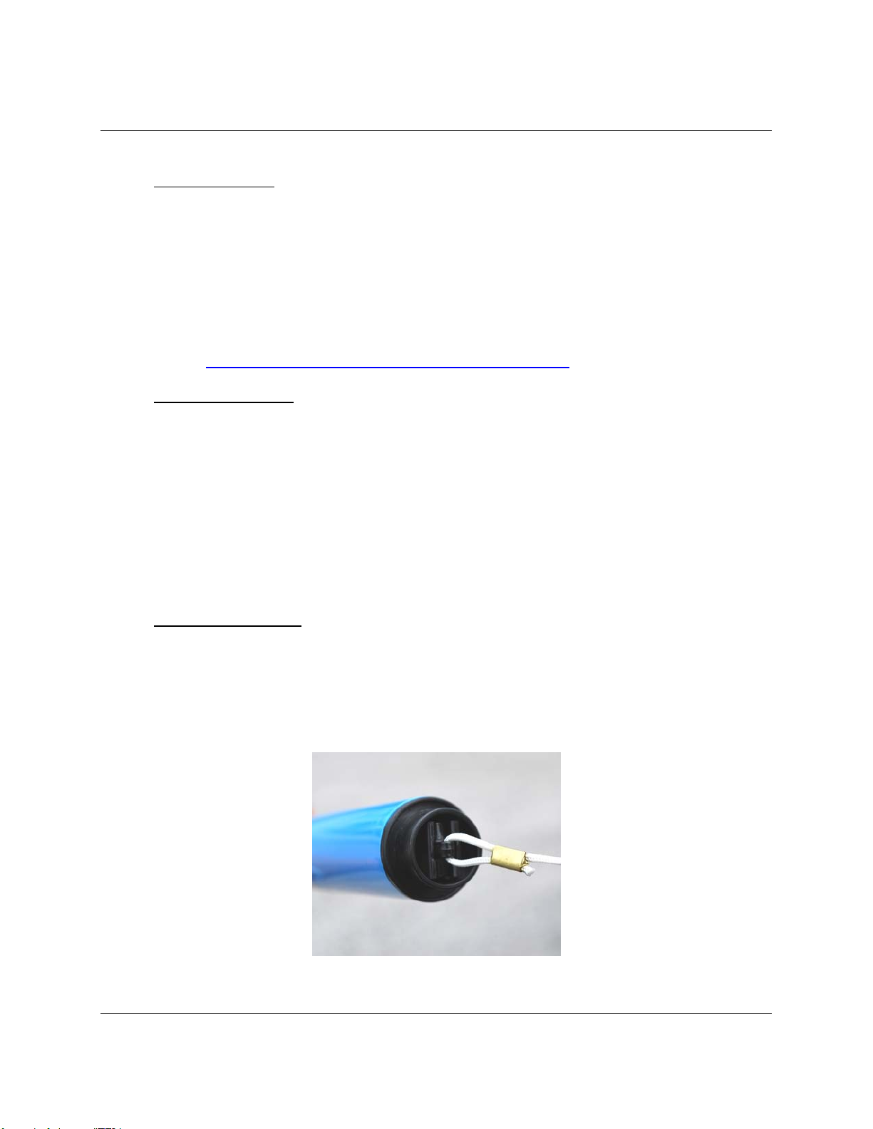
2.3 Theory of Operation
Battery activation and illumination of the escape slide lighting system is accomplished
automatically upon inflation of the host device. An activation lanyard with a switch plug
snaps into a retention clip which is part of the battery’s switch end assembly. The switch
plug, when properly seated in the retention clip, depresses the plunger of the snap-
action microswitch, rendering the battery power circuit open, and the system off. The
lanyard is short-rigged and tied-off, so that inflation and extension of the escape slide
causes the switch plug to be pulled from its retention clip, allowing the microswitch to
snap to the closed circuit condition, providing power to the slide light assembly.
3.0 INSTALLATION, RIGGING and OPERATION
3.1 Installation & Rigging
Install the Model 700-series battery pack in accordance with escape slide manufacturer's
component maintenance manual procedures. Secure the end of the activation lanyard
to the escape slide structure and route it to the battery pack in accordance with the es-
cape slide manufacturer's CMM. Fully install the switch plug (located on the end of the
activation lanyard) into the clip in the switch end of the battery pack per Figure 3. Do not
safety-tie or otherwise obstruct free release of the switch plug from its retention clip.
Figure 3 - Installation of Activation Switch Plug
BASEWEST
Operating & Maintenance Manual
Escape Slide Lighting Batteries - Model 725 thru 785
Page 5 of 7 25-60-51
10 March 2014
3.2 Packing
Care must be taken during the packing process to ensure that sufficient slack is availa-
ble in the activation lanyard to ensure that folding, packing, and compression will not in-
advertently place sufficient tension on the activation lanyard to cause it to pull from the
retaining clip in the end of the battery; such a condition will result in inadvertent activa-
tion of the lighting system and premature depletion of the battery pack.
Further care must be taken to avoid placing the battery in a location that will result in
bending stresses, or point load compression against hard surfaces (e.g., bottles or regu-
lators) within the pack that could compromise the battery pack.
3.3 Operation
The battery pack, when properly installed, secured and rigged in accordance with the
escape slide manufacturer’s instructions, will operate automatically upon inflation of the
escape slide. The activation lanyard is “short-rigged” to the escape slide such that the
activation switch plug will be pulled from the battery when the escape slide is inflated.
3.4 Special Activation Lanyards
Some OEM battery installations call out special activation lanyards - including those with
integral attachment loops, dual activation devices, and DOT fasteners. BaseWest main-
tains TSO C69b authority to allow use of corresponding replacement BaseWest special
lanyards designed to interface with BaseWest's unique battery activation design. Please
contact BaseWest for any special activation lanyard requirements.
4.0 TESTING
4.1 General
4.1.1 BaseWest escape slide light systems are designed to be tested with BaseWest's Model
TS-420 test set or functionally equivalent test units such DME/Astronics Model TU-12
and TU-14. OEM test instructions which call out instructions for testing OEM batteries
with the Models TU-12 or TU-14 are directly applicable to BaseWest Model 700-Series
batteries and the BaseWest Model TS-420 test set. Published GO-NO GO test values
are also directly applicable.

BASEWEST
Operating & Maintenance Manual
Escape Slide Lighting Batteries - Model 725 thru 785
Page 6 of 7 25-60-51
10 March 2014
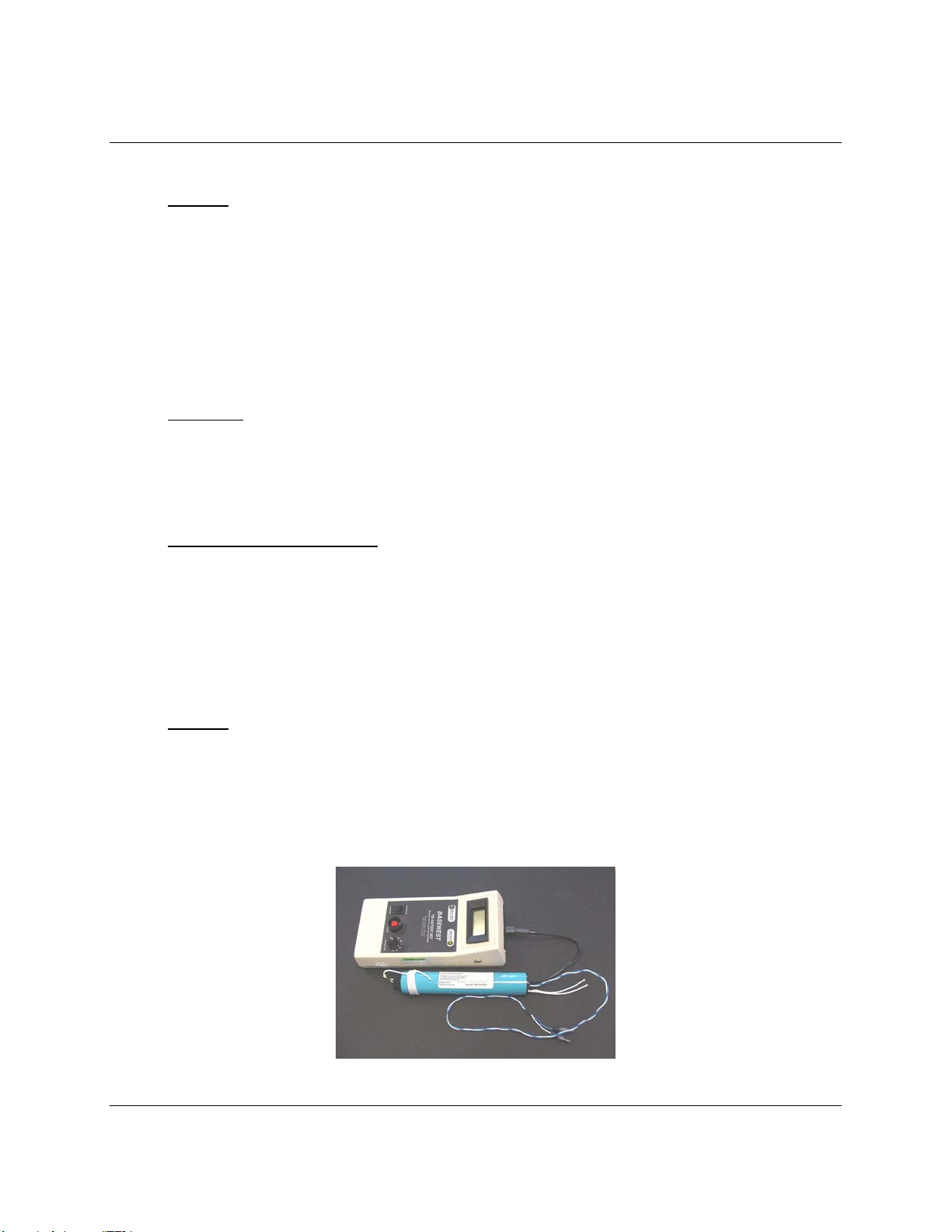
Figure 4 – Battery Testing with TS-420 Test Set
4.1.2 This section applies, generally, to an individual battery, either installed on a slide or
uninstalled. The procedures in this section assume that the battery is testing indepen-
dently, and that it is not attached to slide light harness. This test is suitable for receiving
inspection, pre-installation or pre-packing test.
4.2 Battery Condition Test
This test is designed to verify the condition of the internal battery cells under test load,
only. A functional test of the battery is provided in the next section.
(a) Identify the part number of the battery to be tested (and its OEM cross-reference, if
applicable). Determine the applicable test load settings and GO-NO GO criteria as
published in the applicable OEM maintenance manual.
(b) Gain access to the battery's 4-contact test connector, as shown in Figure 4, and
plug it into the corresponding receptacle on the TS-420 test set (or equivalent).
(c) With switch plug INSTALLED, place the test set in the "VOLTMETER" or battery
test mode. Set the LOAD SELECTOR rotary switch to the proper position ("A"
through "F" or "NO LOAD"), as called out in the OEM maintenance manual.
(d) Press the test set switch and record voltage within 2-3 seconds. Release test
switch.
4.3 Battery Functional Test
This section covers functional testing of the Model 700-Series battery connected to a
slide lighting harness before repacking of the slide. DO NOT PERFORM THIS
PROCEDURE WITH TEST SET CONNECTED TO THE BATTERY.
a) Install the battery, rig the activation lanyard, and connect it to the slide light har-
ness in accordance with slide manufacturer instructions and Section 2.0 of this
manual.
b) With the escape slide laid out fully and all slide light luminaires visible (inflated or
non-inflated), pull the activation switch plug from the battery. Observe that the
slide lights function properly. IMMEDIATELY reinstall the switch plug to de-
activate the battery.
CAUTION: OPERATION OF THE LIGHTING HARNESS WITH THE INSTALLED BATTERY WILL
DEPLETE THE BATTERY.
CAUTION: DO NOT REMOVE CONNECTOR HOUSINGS OR CONTACT INSULATORS FROM
THE POWER LEADS EXCEPT AS NECESSARY TO CONNECT THE BATTERY TO THE
LIGHTING HARNESS. DO NOT ALLOW THE BARE CONNECTOR CONTACTS TO TOUCH; THIS
WILL CAUSE A MOMENTARY SHORT CIRCUIT AND CAN REDUCE BATTERY CAPACITY
SIGNIFICANTLY.

BASEWEST
Operating & Maintenance Manual
Escape Slide Lighting Batteries - Model 725 thru 785
Page 7 of 7 25-60-51
10 March 2014
5.0 MAINTENANCE
5.1 General
BaseWest's Model 700-Series batteries are non-repairable, non-rotable items that have
a limited service life of five (5) years from date of manufacture. Repairs are not autho-
rized. Do not recharge.
5.2 Storage
The Model 700-Series batteries should be stored in a dry, temperature-controlled area at
nominal room temperature or cooler. They should remain in their primary unit packing
until pulled from stock for use. Do not expose the power lead contacts to contact with
conductive materials, or to contact with each other. Maintain the switch plug fully seated
and connector housings and/or insulation sleeves on power lead contacts at all times.
5.3 Service Life
The Model 700-Series batteries are FAA-approved for a five (5) year service life; both
the manufacture date and replace-by date are marked on the battery nameplate.
5.4 Transportation & Disposal
For information relating to transportation and disposal, please refer to the Energizer do-
cumentation provided in the internet links in Section 2.2.
This manual suits for next models
14
Table of contents
Popular Lighting Equipment manuals by other brands

King gates
King gates IDEALED Instructions and warnings for installation and use

Anslut
Anslut 019920 operating instructions

Astrapool
Astrapool NET ‘N’ CLEAN 26985 Installation

Clevertronics
Clevertronics L10 Supalite LFLLED Series ASSEMBLY, INSTALLATION & MAINTENANCE INSTRUCTIONS

Current
Current Lumination Tetra AL10 Series installation guide

Toast
Toast YC ONION LED Light user manual


