USER MANUAL
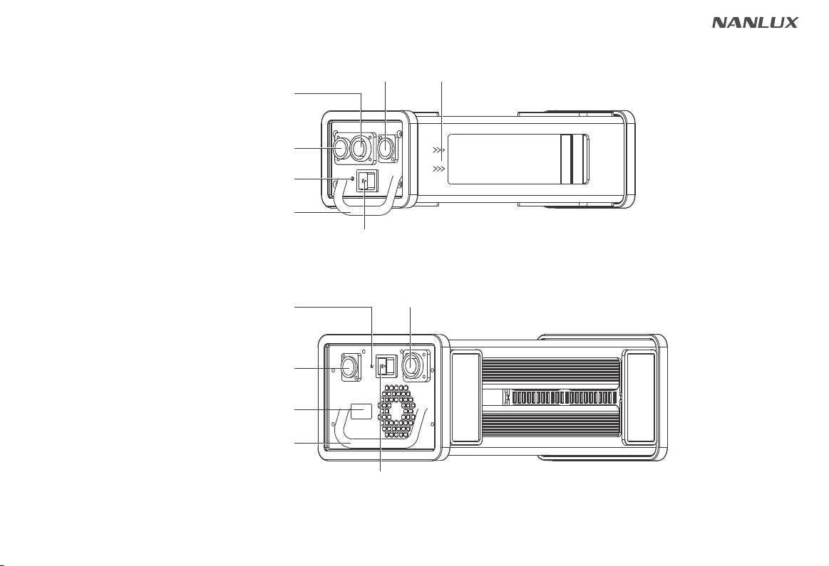
Product Diagram
Technical Data
Product Details
Detailed Description
Usage
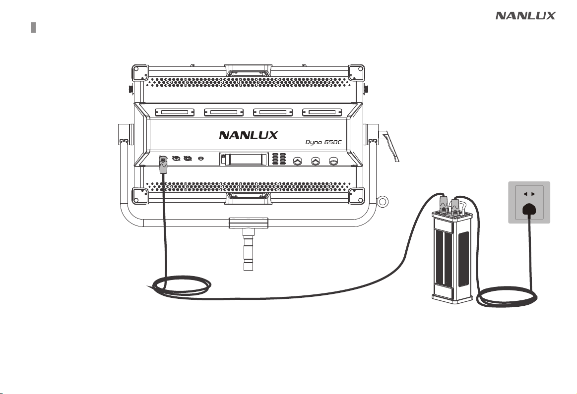
1. Connection between Dyno 650C and Power Supply
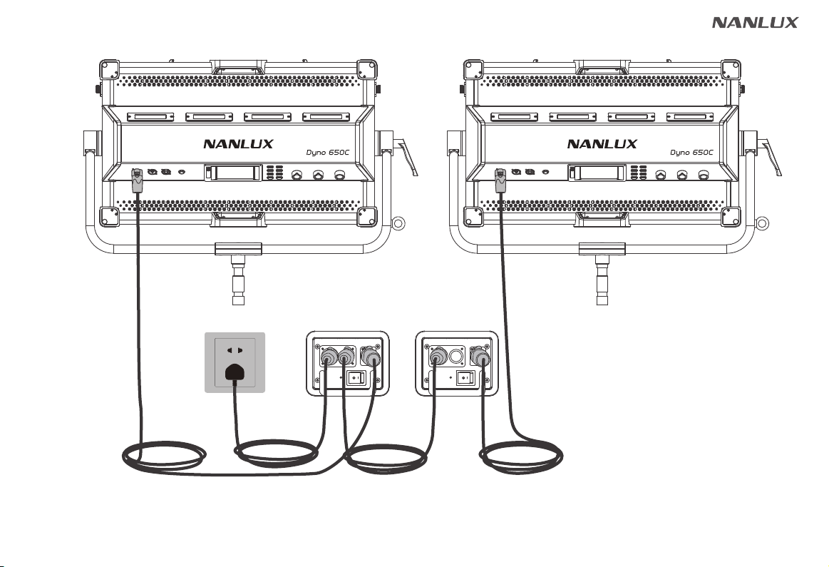
2. Connection between two Dyno 650C and Power Supply
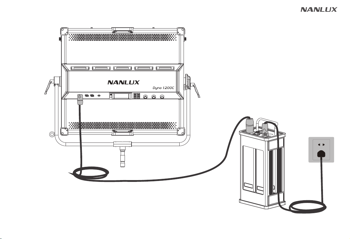
3. Connection between Dyno 1200C and Power Supply
4. Light Stand Clamp Installation
5. Diffuser Installation
6. Barndoor Installation
7. Hanging Options
Remote Control
1. ADDRESS/DMX
2. DMX Remote Control
3. 2.4G Remote Control
4. RDM Remote Control
5. LUMENRADIO Remote Control
Operating Instructions
1. Screen Interface Display Instructions
2. CCT Key
01
....................................................
01
.........................................................
02
.......................................................
.............................................
05
04
.............
06
.......
07
...........
08
........................................
09
......................................................
10
....................................................
11
...........................................................
12
.............................................................
15
.....................................................
17
.....................................................
17
.....................................................
17
........................................
23
..............................
23
......................................................................
①
CCT LIGHTING MODE
②
ADDRESS/DMX
③
LUMENRADIO SETTINGS
④
FAN CONTROL
⑤
ROTATE SCREEN
⑥
SCREEN BRIGHTNESS
⑦
BUTTON BACKLIGHT
⑧
LANGUAGE
⑨
RESET ALL SETTINGS
⑩
LOCK Key
3. HSI Key
4. XY/RGBW Key
5. GEL Key
6. EFFECT Key
7. PRESET Key
8. MENU Key
Fan Exception Indication
25
.......................................................................
26
...............................................................
29
.................................................................
51
.................................................................
28
......................................................................
61
...............................................................
63
.................................................
63
.................................................................
60
..................................................
59
................................................
58
.......................................................
57
...........................................................
57
.............................................
56
..........................................................
56
..................................................
63
.....................................
Safety Precautions 63
.................................................
Notice 64
...........................................................................
General Fault Detection and Diagnosis 64
........
Product Includes 65
....................................................
Contents