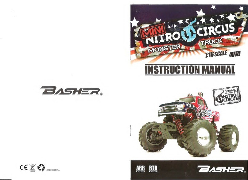
Basher NITRO CIRCUS User manual

Officially
Licenced by
SAFETY PRECAUTIONS

BEFORE YOU RUN YOUR CAR
Required equipement for operation
1. Tools required for building and maintenance:
Hobby knife Precision ruler or caliper Needle nose pliers
Hobby scissors Philips screwdriver
Hex wrench
Wire cutters
Thread locking compound
Cross wrench CA glue & rubber cement
IMPORTANT!!!
Check all the screws are tight before using the car!
Check all the screws are still tight after every battery
pack used in the car!
RECOMMENDED
Use thread lock on all scews that work loose.
PLEASE READ BEFORE STARTING!
Thank you for selecting our racing product ! This vehicle is designed to be fun to drive and uses
good quality parts for durability and performance. The instruction manual you are reading was
designed to be easy to follow yet thorough in its explanations. We want you to enjoy driving your
new R/C car. Well, before you throw down this manual and unleash your new vehicle, please
continue reading for just a few short minutes.
SAFETY GUIDELINES
The vehicle is not intended for use by children without direct supervision of a responsible,
knowledgeable adult. We shall not be liable for any loss or damages, whether direct or indirect
special, incidental, or consequential, arising from the use, misuse, or abuse of this product and/or
any product or accessory required to operate this product.
1

IMPORTANT POINTS TO REMEMBER
Always, turn on your transmitter first before turning on your vehicle receiver switch. When turning an
R/C vehicle off, the order is just the opposite: Turn the receiver switch off first and then turn the trans-
mitter off. Just remember that when your vehicle is turned ON, your transmitter should always be turned
ON. If not, your vehicle will no longer be under the control of your transmitter, and could unexpectedly
take off on its own, causing damage to itself and other people.
Never use old, worn out batteries in your transmitter or vehicle. Use only fresh batteries or fully charged
rechargeable batteries to ensure that you will not exceed the range of your radio system while driving
your vehicle. It is also very important to stop your vehicle immediately when you begin to see that it is
slowing down. This means the batteries in your vehicle are close to being fully discharged, and if you
continue to run your vehicle after it has slowed, it may run "out of control" since it does not have suffi-
cient voltage left to receive the signals from your transmitter.
Only run your vehicle in safe, open areas that will not put anything or anyone in danger of a collision.
Use common sense when driving your vehicle to ensure that you are not causing a potential hazard
to anyone(crowds of people and confined areas should be avoided). Although the model is small
and light weight, it can still hurt when it runs into your ankle height. It can also startle someone who
is not expecting it, so it is extremely important to ALWAYS keep a safe distance between any people
and the path of your vehicle(don't forget this includes yourself)!
Never run your vehicle through puddles, wet grass, snow or any other type of moisture. Also never
use any liquid cleaners around the electronic components on your vehicle. Any small amount of
moisture can cause severe damage to your electronics.
If you be running your vehicle with other R/C vehicles, always confirm before turning your transmitter
on, that no one else is using your same frequency channel. If neccessary, you may change fre-
quencies(certainly this is not related to 2.4G radio use).
Always let your motor and battery cool down completely between runs. The motor needs to cool
completely at the end of a charge before using again. Heat is a big enemy of electric motors.
Overheating the motor will shorten its life and can cause it to fail. Prolonged running on high drag
surfaces like grass, carpet etc.can heat the motor up and cause possible failure.
WHAT ELSE IS NEEDED
4 "AA" alkaline batteries(for the radio transmitter)
GETTING STARTED
1. INSTALLING TRANSMITTER BATTERIES
Install 4 new "AA" batteries into your vehicle transmitter.
Check the life and proper installation of your batteries by switching the transmitter to ON. On vehicle
transmitters, you should see all three LED'S light up(Red, yellow, and green). If you do not, your
batteries may be low on voltage or you may not have installed them all correctly.
As the life of your transmitter batteries begins to decline, the green LED will no longer light. When you
notice that you are down to only the yellow and red lights, this is a caution sign that it is time to install
new batteries. If you continue operating your vehicle, and see that the yellow light goes out(and only
the red light is lit), STOP IMMEDIATELY! Your vehicle may easily travel out of range causing you to
lose all control, which could result in a collision causing damage to the vehicle or other property.
-2-
2

2. CHARGING YOUR VEHICLE
Charge your vehicle's battery pack. Connect the charger in the box to your battery pack(it will only plug
in one direction) and then plug the charger into a standard wall outlet. Charging takes approximately
2-3 hours. When the battery is fully charged, unplug the charger and connect the battery to your
speed control.
Your vehicle charger will safely charge your battery pack and not over charge it. Be careful when using
after market chargers that you do not overcharge the battery pack and ruin it. By the way, this chargeris
only for the vehicle, not for the radio control.
3. ASSEMBLING THE ANTENNA
Locate the plastic antenna tube.
Run the antenna wire up through the rear antenna mount hole in the upper chassis plate and begin
feeding it into the plastic antenna tube until it comes out the other side. Pull the remaining wire through
the tube, and then press the tube into the antenna mount in the upper chassis plate. Bend the antenna
wire down around the tube and install the black rubber antenna cap on the top of the tube. You may then
wrap the remaining wire arount the tube. DO NOT cut the antenna wire off! This could shorten the range
of your radio system.
Special Instruction About Batteries
Contents:
1. Keep batteries/storage batteries out of reach of children.
2. Do not let batteries lie around openly, There is a risk of batteries being swallowed by children or pets.
In such case, seek instant medical care!
3. Batteries/Rechargeable batteries must never be short-circuited, taken apart or thown into fire.They
might explode!
4. Leaking or damage batteries/rechargeable batteries might cause acid burns when getting into contact
with skin. Therefore, use suitable protective gloves.
5. Conventional batteries must not be recharged. Danger of fire and explosion! Only charge rechargeable
batteries which are intended for this purpose, use suitable rechargeable battery chargers.
6. Pls observe correct polarity of batteries/rechargeable batteries and the connection of a re-chargeable
battery pack(note plus/+ and minus/-) when inserting the batteries.
7. If the device is not used for a longer period of time (eg storage), take out the inserted batteries/
rechargeable batteries of the remote control to avoid damage from leaking batteries/rechargeable
batteries.
Recharge the rechargeable battery about every 3 months, because otherwise there may a so called
deep discharge because of the self discharge, which makes the rechargeable batteries useless.
8. Always exchange the entire set of batteries or rechargeable batteries, Do not mix full batteries/
rechargeable betteries with half-full ones. Always use batteries or rechargeable batteries of the same
type and manufacturer.
9. Never mix batteries and storage batteries. Either use eight batteries or eight rechargeable batteries
for the remote control/transmitter.
Please Note:
Before the rechargeable battery pack delivery its maximum power, several complete dis-charge and
charge cycles are necessary
Always drive the rechargeable battery pack empty, since recharging a “half - full” rechargeable battery
pack can cause a so called memory effect. That means that the rechargeable battery pack loses its
capacity, it no longer releases all of its saved energy, drive time is decreased.
If you are using several rechargeable battery packs or rechargeable batteries, purchasing a high quality
charger maybe worthwhile.
They are normally also suitable for fast charging of rechargeable batteries.
- 3 -
3

Disposal:
The user is legally obliged(battery regulation) to return used batteries and storage batteries.
The user is legally obliged(battery regulation) to return used batteries and storage batteries.
Do not dispose of used batteries via the household rubbish!
Batteries/storage batteries containning harmful substances which been disposed via the household
rubbish is prohibited.
You can return used batteries/accumulators free of charge to any collecting point in your local
authority, so that you comply with your legal obligations and make your contribution to enviromental
protection.
Special Instruction for ESC
Attention:
Do not use any force when plugging in it!
For reason of safety place the rechargeable battery pack on a non-flammable surface, eg. a tiled floor.
Keep the rechargeable battery pack away from flammable objects.
Never leave the rechargeable battery pack unattended.
The rechargeable battery pack gets warm during charging, this is normal.
Separate the rechargeable battery pack from the plug-in charger after charging, pull the plug-in charger
from the mains socket.
Before using the rechargeable battery pack in the vehicle, wait untill it has completely cooled down.
After your playing, please do not forget to cut the connections of battery and ESC!
rechargeable battery pack has cooled down before you recharge.(min. of 5-10 minutes)
Connect the plug-in charger with a proper mains socket.
Connect the rechargeable battery pack with correct polarity with the plug-in charger.
Normally the special design of the two plugs avoids the incorrect connection of the rechargeable batter
【DECLARATION】
Thanks for purchasing the Electronic Speed Controller (ESC). High power system for RC model can
be very dangerous, please read this manual carefully. In that we have no control over the correct use,
installation, application, or maintenance of our products, no liability shall be assumed nor accepted for
any damages, losses or costs resulting from the use of the product. Any claims arising from the
operating, failure of malfunctioning etc. will be denied. We assume no liability for personal injury,
consequential damages resulting from our product or our workmanship. As far as is legally permitted,
the obligation to compensation is limited to the invoice amount of the affected product.
【FEATURES
】
► Compatible with all sensorless brushless motors.
► Excellent start-up, acceleration and linearity features.
► Built-in switch mode BEC has a powerful output to supply all the electronic equipments.
► User programmable. Easily programmed with the “SET” button on the ESC and also compatible
with the 3 digital LEDs Program Card.
► 3 running modes (Forward mode, Forward/Reverse mode, Rock Crawler mode)
► 4 steps of maximum reverse force adjustment.
► Proportional ABS brake function with 4 steps of maximum brake force adjustment, 8 steps of
drag-brake force adjustment and 4 steps of initial brake force adjustment.
► 9 start modes (Also called “Punch”) from “very soft (Level 1)” to “very aggressive (Level 9)”.
► 8 steps of timing adjustment to suitable for all brushless motors.
► Multiple protection features: Low voltage cut-off protection / Over-heat protection / Throttle signal
loss protection / Motor blocked protection.
► Splash proof and dustproof.
For this purpose, proceed as follows:
If the rechargeable battery pack was taken directly from the vehicle and is still hot, wait until the
4

- 5-
【SPECIFICATIONS】
Cont./ Burst Current A059/A051A083/A08
Resistance mho2000.0mho6000.0
Suitable Car 1/8 on-road, off-road and
monster RTR applications
1/5, 1/8 on-road, off-road and
monster
applications
Super powerful
Sensorless Brushless Motors
≥4.5T, KV≤3000
(Works with 4S Lipo)
Suitable Motor ≥6T, KV≤2400
The 80A ESC works
with 4S Lipo ≥6T, KV≤2400
(Works with 6S Lipo)
Battery 6-12 cells NiMH or
2-4 cells Li-Po 6-18 cells NiMH or 2-6 cells Li-Po
BEC Output 5.75V@3A Switch mode built-in BEC
Dimension 58mm(L) * 46.5mm(W) * 35mm(H)
Weight 105g (Wires not included)
Cooling Fan Working
Voltage
5V, maximum 8V. (The fan gets the power supply from the
built-in BEC)
【BEGIN TO USE THE NEW ESC 】
WARNING! THIS BRUSHLESS SYSTEM IS VERY POWERFUL! FOR SAFETY, PLEASE ALWAYS KEEP THE
WHEELS AWAY FROM THE TRACK WHEN YOU BEGIN TO SWITCH ON THE ESC.
1. Connect The ESC, Motor, Receiver, Battery And Servo
The #A, #B, #C wires of the ESC can be connected with the motor wires freely (without any
sequence). If the motor runs in the opposite direction, please swap any two wire connections.
Note1: The small black female connector coming out from the ESC is used for connecting with
the cooling fan of the brushless motor.
5
Model 80A150A

If there are 2 battery packs need to be connected in series,
please refer to the following picture:
2. Throttle Range Setting (Throttle Range Calibration)
In order to make the ESC fit the throttle range, you must calibrate it when you begin to use a new
ESC, or a new transmitter, or change the settings of neutral position of the throttle stick, ATV or EPA
parameters, etc. Otherwise the ESC cannot work properly.
The following pictures show how to set the throttle range with a FutabaTM transmitter.
Note2: If you don’t release the “SET” key as soon as the red LED begins to flash, the ESC will enter
the program mode,in such a case, please switch off the ESC and re-calibrate the throttle range
again from step A to step D.
A) Switch off the ESC, turn on the
transmitter, set the direction of
throttle channel to ”REV”, set the
“EPA/ATV” value of throttle
channel to “100%”, and disable
the ABS function of your
transmitter.
B) Hold the “SET” key and then
switch on the ESC, and release
the “SET” key as soon as possible
when the red LED begins to flash.
(Note2)
6

3. Check The LED Status In Normal Running
►Normally, if the throttle stick is in the neutral range, neither the red LED nor the green LED lights.
►The red LED lights when the car is running forward or backward and it will flash quickly when the
car is braking.
►The green LED lights when the throttle stick is moved to the top point (end point) of the forward
zone or backward zone.
4. Check The Lipo Cells Setting If You Are Using Lithium Battery
If you are using Lipo battery, we strongly suggest setting the “Lipo Cells” programmable item
manually to avoid the over-discharge problem. Please read the instructions on page 10.
In normal case, when the ESC is switched on, the motor will emit several “Beep” tones to express
the cells amount of the battery pack. For example, “Beep-Beep-” means 2s Lipo,
“Beep-Beep-Beep-” means 3s Lipo, etc.
C) Set the 3 points according to the
steps shown as the pictures on the
right side.
1) The neutral point
Move the throttle stick at the neutral
point, and then click the SET key, the
green LED flashes 1 time.
2) The end point of forward direction
Move the throttle stick at the end point
of forward direction, and then click the
SET key, the green LED flashes 2
times.
3) The end point of backward
direction
Move the throttle stick at the end point
of backward direction, and then click
the SET key, the green LED flashes 3
times.
D) Throttle range is calibrated; motor can
be started after 3 seconds.
7

- 8-
2. Explanation For Each Programmable Item
2.1. Running Mode: With “Forward with Brake” mode, the car can go forward and brake, but cannot
go backward, this mode is suitable for competition; “Forward/Reverse with Brake” mode provides
backward function, which is suitable for daily training.
Note: “Forward/Reverse with Brake” mode uses “Double-click” method to make the car go backward.
When you move the throttle stick from forward zone to backward zone for the first time (The 1st
“click”), the ESC begins to brake the motor, the motor speeds down but it is still running, not
completely stopped, so the backward action is NOT happened immediately. When the throttle stick
is moved to the backward zone again (The 2nd “click”), if the motor speed is slowed down to zero (i.e.
stopped), the backward action will happen. The “Double-Click” method can prevent mistaken
reversing action when the brake function is frequently used in steering.
By the way, in the process of brake or reverse, if the throttle stick is moved to forward zone, the
motor will run forward at once.
“Forward/Reverse” mode uses “Single-click” method to make the car go backward. When you move the
throttle stick from forward zone to backward zone, the car will go backward immediately. This mode
is usually used for the Rock Crawler.
“Forward /Reverse with Brake=0%” mode uses like“Forward/Reverse with Brake” method to make the car
go backward, but brake force is 0%, this mode is cancel electronic brake, to replace use one servo to
make the car brake. (like oil car ,use machine function make brake)
2.2. Drag Brake Force: Set the amount of drag brake applied at neutral throttle to simulate the slight
braking effect of a neutral brushed motor while coasting.
2.3. Low Voltage Cut-Off: The function prevents the lithium battery pack from over discharging. The
ESC detects the battery’s voltage at any time, if the voltage is lower than the threshold for 2 seconds,
the output power will be reduced 70%, after 10 seconds the output will be completely stopped, and
the red LED flashes in such a way: “☆-☆-, ☆-☆-, ☆-☆-”.
1 2 3 4 5 6 7 8 9
1. R unning Mode Forward
with Brake
Fo rward /Rever
se
with B rake
Forward and
R eve rs e
Forword
without brake
and Reverse
2.D rag Bra ke F orc e 0% 5% 10% 20% 40% 60% 80% 100%
3.Low Voltage
C ut-Of f T hreshold Non-Protec tion 2.6 V/Ce ll 2.8V/Cell 3.0V/C ell 3.2V
/Cell
3.4V
/Cell
4.Start Mode(Punch) Level1 Level 2 Level3 Level4 Level5 Level 6 Level7 Level8 Level9
5.Max Brake Force 25% 50% 75%100%
6.Max R eve rs e F orc e 25%50% 75% 100%
7.Initial Brake Force = D rag Brake
F orce 0% 20% 40%
8.Neutral Range 6% (Narrow) 9% ( No rmal) 12% (W ide)
9.T iming
(On ly f or se ns orless
motor)
0.00 ° 3.75 ° 7.50 ° 11.25 ° 15.00 ° 18.75 ° 22.50° 26.25°
10.Over-heat Protection En able D isable
11.Motor Rotation C ounter
Clockwise C loc kwise
12.Lipo Cells Au to Calcu late 2 Cells 3 Cells 4 Cells 5 C ells 6 Cells
Programmable
Items
Adv anced Items
Basic Items
Options
【PROGRAM THE ESC】
1. Programmable Items List (The italics texts in the form are the default settings)
8

There are 6 preset options for this item. You can customize the cutoff threshold by using an
advanced LCD program box (optional equipment) to trim it with a step of 0.1V, so it will be more
suitable for all kinds of batteries (NiMH, NiCd, Li-ion, Lipo, LFP,etc). Please always keep in mind that
the customized value is not for each cell, it is for the WHOLE battery pack.
2.4. Start Mode (Also called “Punch”): Select from “Level1” to “Level9” as your like, Level1 has a
very soft start effect, while level9 has a very aggressive start effect. From Level1 to Level9, the start
force is increasing. Please note that if you choose “Level7” to “Level9” mode, you must use good
quality battery pack with powerful discharge ability, otherwise these modes cannot get the burst start
effect as you want. If the motor cannot run smoothly (the motor is trembling), it may caused by the
weak discharge ability of the battery pack, please choose a better battery or increase the gear rate
(Use a smaller pinion).
2.5. Maximum Brake Force: The ESC provides proportional brake function. The brake force is related
to the position of the throttle stick. Maximum brake force refers to the force when the throttle stick is
located at the top point of the backward zone. A very large brake force can shorten the brake time,
but it may damage the gears.
2.6. Maximum Reverse Force: Sets how much power will be applied in the reverse direction. Different
value makes different reverse speed.
2.7. Initial Brake Force: It is also called “minimum brake force”, and it refers to the force when the
throttle stick is located at the initial position of the backward zone. The default value is equal to the
drag brake force, so the brake effect can be very smoothly.
2.8. Throttle Neutral Range:Please refer to the following picture to adjust the neutral range as your
like.
9

2.9. Timing: The “timing” item is usable for sensorless brushless motors. There are many
differences among structures and parameters of different brushless motors, so a fixed timing ESC is
difficult to compatible with all brushless motors. It is necessary to make the timing value
programmable. Please select the most suitable timing value according to the motor you are just
using. Generally, higher timing value brings out higher power output, but the whole efficiency of the
system will be slightly lower down.
2.10. Over-Heat Protection: If the function is activated, the output power will be cut-off when the
temperature of the ESC is higher than a factory-preset value for 5 seconds. When the protection
happens, the Green LED will flash as “☆-, ☆-, ☆-”.
2.11. Motor Rotation: You can use this item to change the rotation direction. Face to the motor shaft
(That means the rear cover of the motor is far from your face), and move the throttle stick to the top
point of the forward zone. If this item is set to “CCW”, the shaft runs counter-clockwise; If this item is
set to “CW”, the shaft runs clockwise.
2.12. Lipo Cells: We strongly suggest setting the “Lipo Cells” item manually. Because the normal
voltage of each Lipo cell varies from 2.6V to 4.2V, it is quite difficult to calculate the cells number of a
discharged Lipo battery pack. If it is calculated incorrectly, the Low Voltage Cutoff Protection
function may work abnormally, so the option “Auto Calculate” is only available for 2s, 4s and 6s Lipo.
If the voltage of the battery pack is lower than 8.8V, it is judged as a 2s Lipo; If the voltage is
between 8.8V to 17.6V, it is judged as a 4s Lipo; If the voltage is higher than 17.6V, it is judged as a
6S Lipo. So in order to make the Low Voltage Cutoff Protection function always works correctly,
please set the “Lipo Cells” item manually.
3. Program Methods
A) Program the ESC with LED program card (Optional equipment )
Please refer to the user manual of LED program card.
B) Program the ESC with the SET button on the ESC
Please refer to the instructions on page 12.
4. Reset All Items To Default Values
At any time when the throttle is located in neutral zone (except in the throttle calibration process or
ESC program mode), hold the “SET” key for over 3 seconds, the red LED and green LED will flash
at the same time , which means each programmable item has be reset to its default value.
【ALERT TONES】
1. Input voltage abnormal alert tone: The ESC begins to check the input voltage when power on, if
the voltage is out of the normal range, such an alert tone will be heard: “beep-beep-, beep-beep-,
beep-beep-” (There is 1 second interval between every group of “beep-beep-” tone).
2. Throttle signal abnormal alert tone: When the ESC can’t detect the normal throttle signal, such
an alert tone will be heard: “beep-, beep-, beep-” (There is 2 seconds interval between every “beep-”
tone).
10

【TROUBLE SHOOTING】
Flow chart: Program the ESC with the SET key
After power on, motor doesn’t
work, and the cooling fan
doesn’t work
The connections between
battery pack and ESC are
not correct
Check the power connections
Replace the connectors
After power on, motor can’t
work, but emits “beep-beep-,
beep-beep-” alert tone. (Every
group of “beep-beep-” has a
time interval of 1 second )
Input voltage is abnormal,
too high or too low
Check the voltage of the battery
pack
After power on, red LED
always lights, the motor
doesn’t work
Plug the control wire into the
throttle channel of the receiver
correctly.
The motor runs in the opposite
direction when it is accelerated
1)The wire connections
between ESC and the motor
are not correct
2)The chassis is different
from the popular design
Swap any two wire connections
between the ESC and the motor.
Or change the “Motor Rotation”
programmable item to
“CW(Clockwise)”
1)Check the transmitter and the
receiver
2)Check the signal wire from the
throttle channel of your receiver
The motor suddenly stops
running while in working state The ESC has entered the
Low Voltage Protection
Mode or Over-heat
Protection Mode
Red LED flashing means Low
voltage protection. Green LED
flashing means Over-heat
protection
When accelerating quickly, the
motor stops or trembles
1)The battery has a bad
discharge performance
2)The gear rate is too small
3) The “Start Mode (Punch)”
of the ESC is too aggressive
1) Use a better battery
2) Use lower KV motor or change
the gear rate, choose smaller
pinion
3) Select a softer option for the
“Start Mode (Punch)”
11
Trouble Possible Reason Solution
Throttle signal is abnormal
The throttle signal is lost

Note4:
In the program process, when the LED is flashing, the motor will emit “Beep” tone at the same
time.
If the number “N” is bigger than the “5”, we use a long time flash and long “Beep---” tone to
represent “5”, so it is easy to identify the items with bigger series number.
For example, if the LED flashes as the following:
“A long time flash + 1 short time flash” (Motor sounds “Beep---Beep”) =the No.6 item
“A long time flash + 2 short time flashes” (Motor sounds “Beep---BeepBeep”) =the No.7 item
“A long time flash + 3 short time flashes” (Motor sounds “Beep---BeepBeepBeep”) =the No.8item
…… And so on.
12

Declaration Of Using Our Products
Even if the vehicle is quite small at the first glance, there is risk of injuries in the case of crash with
people(or animals), because of the high acceleration capacity and the high achievable speed.
Sharp edges and rotating parts also present a high danger!
This is why you should drive very responsibly and carefully, this is especially the case for
inexperienced drivers.
So, here we declaration as below:
1. Please do note this manual carefully, especially the attentions parts and if you are a new player
without enough experience, we will not take any responsibility for the car damages or injuries
caused by incorrect operation!
2. Please do not change the matches of the brushless ESC, motor and the Li-Po battery casually, if
you want to make a change, please do ask for ideas of professional people, incorrect and unsuitable
matches will effect the functions and the car’s high performance, even it will cause the damages of
the electronic parts and the crash of the car!
We do not take the responsibility of car damages and injuries of unsuitable matches or equipment changes!
3. We have right to change the specification and parameter of the model and without notice in
advance pls take the material object as the standard!
2.4GHz radio manual
1) Transmitter
2) 2.4GHz Frequency Pin Setup
13

14
1.Diff.Gearbox completed
BS32829
2.Gearbox completed
BS32829
BS32830
BS32848
BS32848
BS32848
BS32858
BS32858
BS
Or
BS32032(hop ups)
32859
BS32861
BS32865
BS32862
BS32868
BS32868
BS32895
BS32864
BS32897
BS32897
BS32632
BS32632
BS30095
BS30095
BS33166
BS32902
BS32980
BS32983
BS32927
BS
Or
BS32032(hop ups)
32859

BS32833
4.Aluminum Shock Assembly
BS32833
BS32833
BS32833
BS32833
BS33518
BS32891
BS32891
BS32891
BS32891
BS32892 Or BS32034(hop ups)
BS32896
-15-
BS32928
BS
BS32035(hop ups)
32833 Or
BS
BS32046(hop ups)
32877 Or
BS
BS32041(hop ups)
32890 Or
BS
BS33550(hop ups)
33520 Or
15
3.Aluminum Shock Components

16
5.Central Diff.Box completed
6.Servo completed
BS33510
BS32887
BS
Or
BS33535(hop ups)
33507
BS33517
BS33516
BS33506
BS30074
BS30074
BS32726
BS32178
BS30103
BS32726
BS32726
BS30837
BS30837
B1138
BS32858
BS32897
BS32632
BS32868
BS32868
BS32858
BS32897
BS32897
BS32895
BS32865
BS32830 BS32848
BS32848
BS30095
BS30095
BS
BS
32866 Or
32981(hop ups)
BS30839
BS
BS 3538
33525 Or
3(hop ups)
BS
BS 3538
33525 Or
3
(hop ups)
BS
BS 2033
32867 Or
3(hop ups)
BS
BS 2033
32867 Or
3
(hop ups)

7.Servo Saver completed
BS32823
BS32823
BS32823
BS32823
BS32823
BS32824
BS32824
BS32824
BS32825
BS32825
Or
BS32879
BS32879
BS32880
BS32880
BS32823
BS32823
8. Motor
-17-
BS33524
BS33511
BS32920
B1109
BS33511
BS 29883
BS32878
BS32028(hop ups)
17

18
9.Body completed
10.Completed Truck
BS33527
BS32612
BS32612
BS33527
BS33527
BS33527
BS33527
B1148
BS32902
BS30837
BS30099
B0052P
B1148
B1148
B1148

19 20
- 20 -
9.A2020 Exploded view
BS32843
BS33510
BS33528
BS32801
BS33532
BS32832
BS32832
BS32832
BS32833
BS32833
BS32833
BS32833
BS33533
BS33510
BS33510
BS33204
BS33204
BS33512
BS33513
BS33514
BS32868
BS33519
BS33502
BS33502
BS33503
BS33504
BS33505
BS33508
BS33509
BS33509
BS33509
BS33509
BS33111
BS33111
BS32726
BS32726
BS32726
BS32726
BS30081
BS30833
BS32612
BS32612
BS30083
BS30083
BS30083
BS30083
BS30083
BS30860
BS30860
BS30860
BS30837
BS30837
BS30837
BS32906
BS32906
BS30104
BS30104
BS32912
BS32912
BS32912
BS32912
BS32912
BS32912
BS32912
BS32912
BS32909
BS30095
BS30095
BS30083
BS32900
BS30240
BS33210
BS30099
BS30099
BS30099
BS30099
BS32907
BS32877 BS32877
BS32876
BS32876
BS33230
BS33230
BS32821
BS32822
BS32832
BS32832
BS32851
BS32829
BS32842
BS30085
BS32841
BS30841
BS33166
BS33166
BS33166
BS33166
BS32905
BS30791
BS33232
BS32844
BS32892
BS33522
BS32846
BS32847
BS32848
BS32849
BS33500
BS33251
BS32919
BS32839
BS32850
BS32850
BS32726
BS30083
BS30083
BS32903
BS32903
BS32903
BS32903
BS32726
BS32892
BS33208
BS32911
BS32911
BS32899
BS32916
BS30103
BS30103
BS30103
BS33237
BS32908
BS32908
BS32844
BS32848
BS32849
BS32847
BS30860
BS32908
BS33232
BS32843
BS32832
BS33111
BS32832 BS32846
BS32905
BS30103
BS32892
BS33523
BS32857
BS33501
BS33166
BS33231
BS32726
BS32726
BS32822
BS33521
BS32829
BS32829
BS30841
BS33166
BS33166
BS32832
BS32842
BS30095
BS33208
BS30083
BS32855
BS32919
BS33251
BS32903
BS32903
BS32903
BS32911
BS32911
BS32612
BS32612
B1097
B1115
BS32913
BS33518
BS33518
BS32877
BS32877
BS32832
BS32832
BS30240
BS33210
BS32912
BS32912
BS32892
BS33526
BS33526
BS33231
BS33533
BS33533
BS33533
BS33528
BS33528
BS33528
BS33528
BS33532
BS33528
BS33528
BS33528 BS33528
BS33528 BS33528
BS33533
BS33533
BS33533
BS33533
Table of contents
Other Basher Toy manuals
Popular Toy manuals by other brands

Black Horse Model
Black Horse Model ROCKWELL AERO COMMANDER SHRIKE instruction manual

Fisher-Price
Fisher-Price Hoops-Basketball manual
WowWee
WowWee Robosapien X supplementary guide

Lionel
Lionel SD-40-2 Husky Stack owner's manual

Eduard
Eduard MiG-21SMT Assembly instructions

Black Horse Model
Black Horse Model YAK 54 instruction manual
