BASI BCOT751 User manual

BASI Instrument AB, P.O.Box 53, SE-275 06 VOLLSJÖ, SWEDEN
tel: +46 (0)40 88009, fax: +46 (0)40 929877, e-mail: info@basi.se
BCOT751
OPERATION MANUAL
SMART ISOLATED
CONDUCTIVITY TRANSMITTER
v2-1-06.18

Overview
2
BCOT751 is a smart isolated
conductivity transmitter with automatic
temperature compensation.
The device is fully programmable
with all its parameters accessible by PC
via its communication interface.
Mounting and Wiring
Mounting
BCOT751 can be easily mounted on every
35 mm rail conforming to EN50022.
Wiring
♦Connect a conductivity cell
to terminals 5 and 6(7) and
a temperature compensation sensor
to terminals 7(6) and 8.
Terminals 6 and 7
are internally connected.
♦Get the analog output signal
from terminals 2(+) and 4(-).
♦Wire the relay output
via terminals 3 and 4.
♦Connect the right power supply
voltage (see 'Specifications')
via terminals 1(+) and 4(-).
♦In order to minimize measuring errors,
make sure the connecting screws
are tightened enough.

Communicating
3
♦
Install standard FTDI Cable Driver
on your PC.
♦
Connect BCOT751 to the PC
via communication cable model K12U.
♦
Use an applicable terminal application
(e.g. HyperTerminal) and follow
the requirements of the described protocol
to communicate with the device.
rogramming
Some parameters
are accessible only
when the respective
functionality is installed.
(see 'Specifications').
- Changing Point Position value
reflects on the real value
of all parameters
with the conductivity
measurement unit.
E.g.: changing Point Position value
from 0to 1would change
a set-point value
of 100 to 10.0.
Device parameters
BCOT751 is a programmable device whose
service behavior is determined by a set
of parameters. All the parameters, along
with their names, symbols, and value ranges,
are given in Table 1.
Parameter programming
BCOT751 is to be programmed
through the communication interface.

Parameter Symbol Description
Input
Parameters
t.v
t.def
t.unit
t.cor
t.comp
t.sens
c.v
c.unit
c.pnt
! f.b "#$$
f.t %
const
&% c.cabr %$
Output
Parameters
o.conf '
'() o.lnk )
($( o.lo *$
+( o.hi *
o.v %
, o.er '
+, er.t
-
%() r.lnk )
r.s.p
-
+ r.his %$
r.dir '
Calibration
P
arameter
cal
, error
./0Relay Output Link
.10AnalogOutput Link
.20Temperature Unit

Table
1
Value Unit Point
Notes
33334/333
321341/13.20t.unit1
$Temperature Compensation 5fixed
c#f
- - c.0#f. 0
333346666
333347777.20%/t.unit
3
sens#
fixed#off
- - sens.0#
fixed.Default Temperature0#off.0
Pt100#pt1000#
ntc1k
- - Pt100./330#pt1000./3330#
ntc1k.8/)0
c.unit c.pnt
mS.cm#uS.cm
- - mS.cm.90#uS.cm.:90
0#1#2#3 - -
34Mc.unit c.pnt
M57;Cell Constant.9057333;Cell Constant.:90
34666 3/9 0
333<33341733333 /9 5#6
333346666 = 3 $
i.0.20
#i.4.20#
u.0.10#u.2.10
- - i.0.20.3413'0#i.4.20.>413'0#
u.0.10.34/30#u.2.10.14/30
cond#temp
- - cond.0#temp.0
333346666 c.unit
t.unit./0
c.pnt
1./0
333346666 - 0
under#over
- - under.0#over.0
33334/33 1
cond#temp
- - cond.0#temp.0
333346666 c.unit
t.unit.10
c.pnt
1.10
heat#cool
- - heat.0#cool.0
no#c.set#
c.cal
- - no.0#c.set.0#
c.cal.?0
0441 - - 'Errors'

Communication rotocol
6
Notes:
♦BCOT751 adds 3 spaces
in the beginning of the response.
♦BCOT751 returns decimal point
even when the value is integer.
♦#13 (CR) is byte 0x0D;
#10 (LF) is byte 0x0A.
Protocol examples:
PC or other device: BCOT751 response:
reading filter time
f.t#13#10 f.t 0015.#13#10
writing filter time of 30
f.t 30#13#10 f.t 0030.#13#10
reading measured conductivity
c.v#13#10 c.v 027.5#13#10
Protocol architecture
♦The protocol is based
on UART protocol with:
Baud Rate - 9600 bps;
Data bits - 8;
Parity Control - Even;
Stop bit - 1.
♦ASCII protocol is used
for communicating,
and the information
is exchanged in frames.
♦Each frame consists of 1,
or 2 words separated
by byte 32 (SPACE),
and ends with bytes 13 (CR)
and 10 (LF). The first word
in the frame denotes
the parameter 'Symbol'
as taken from Table 1 and
the second word (if needed)
is the parameter 'Value',
both spelled with only
small Latin letters (except for
Conducti ity Unitvalue), digits,
dots, and/or the '-' sign.
Reading from a device
♦If the frame consists of
only 1 word, it is recognized
as a command for reading.
♦The device responds to it by
returning the same word and
its value, according to Table 1.
Writing in a device
♦If the frame consists of
2 words, it is recognized
as a command for writing.
♦With writing, transferred are
the same 2 words that
would have been received
at the respective command
for reading from the device
(except for the reset
command).

Communication rotocol
7
invalid command.
@
parity error.
not a number. $
point error.
A
out of range.
read only. -
can't save. $$
-
Other device responses
♦BCOT751 responses in case
of incorrect protocol use
are given on the left.
♦When Error Info value is -1,
the device substitutes
any command for error
reading (see 'Errors').
Reset
To reset the device,
send command reset.
Errors
Value
Parameters Error type
-1
0
1 Cell Constant
2 Filter Time
3 Filter Band
4 Temperature Coefficient
5 Default Temperature
11 Hysteresis ;
12 Set Point- Hysteresis ;
13 Set PointB Hysteresis ;
21 Hysteresis ;;
22 Set Point- Hysteresis ;;
23 Set PointB Hysteresis ;;
31 Hold Time On Error
41 Wire Resistance
;$Relay Output Link5temp
;;$Relay Output Link5cond
♦Writing in the device
may incur discrepancies
in parameter values
that must be resolved
before further operation.
♦To check for an error,
send command error.
♦In case of value -1,
try resetting by sending
command reset.
♦If the problem persists,
send command error
0
to restore the default
(factory) settings.

Temperature Compensation
8
♦To use
the current measured temperature
for temperature compensation,
set parameter Temperature Compensation
to sens (t.comp sens#13#10).
♦For manual temperature compensation,
using the value of the parameter
Default Temperature,
set parameter Temperature Compensation
to fixed (t.comp fixed#13#10).
Set a Default Temperature value
as close as possible
to the operating temperature value.
♦To turn off temperature compensation,
set parameter Temperature Compensation
to off (t.comp off#13#10).
Input Filtration
Low-pass filter
This first-order filter acts ONLY within
a certain band around filter output value.
This has been designed to cut periodic
noises outside the communication signal
spectrum.
♦Filter operation is defined by two
parameters:
Filter Time (defines filter time constant) and
Filter Band
(defines filter active band
around filter output value).
♦If the newly measured value differs
from the filter output by more than
Filter Band, the filter resets
with a new initial output value
(newly measured value).

Output Control
9
Output operation
♦The analog output
operates according
to the values of parameters
Low Limit, High Limit,
andOutput Value.
♦The alarm relay output
operates according
to the control algorithm
parameters - Set Point,
Direction, andHysteresis.
♦When an error is detected,
the relay output deactivates
and the analog output
is held for a certain time,
defined by the parameter
Hold Time On Error.
♦The analog output signal
in case of an error depends
on the value of parameter
Output On Error.
ON/OFF control algorithm
The static characteristic
of an alarm relay controlled
by an ON/OFF algorithm
is shown on the left drawing.

Calibrating
10
Calibration by setting cell constant
♦
To use this method,
set parameter Calibration Mode to c.set
(cal c.set#13#10).
♦
Assign the precise cell constant value,
taken from the certificate
provided with your sensor
or from the sensor label,
to the parameter Cell Constant
(const x.xxxxxx#13#10).
Calibration by adjusting measured value
♦
To use this method,
set parameter Calibration Mode to c.cal
(cal c.cal#13#10).
♦
To take temperature compensation
into account, select the desired
compensation method
via parameter Temperature Compensation.
♦
Place the conductivity cell
into calibration solution
and wait for the measured value
to stabilize (c.v#13#10).
♦
Assign the calibration solution’s
conductivity value
to the Conducti ity Value parameter
(c.v xx.xx#13#10).

Waste Disposal
11
Do not dispose of
electronic devices
together with
household waste
material.
If disposed of within European Union,
this product should be treated
and recycled in accordance with the laws
of your jurisdiction implementing
Directive 2012/19/EU on waste electrical
and electronic equipment (WEEE).

Specifications
12
Conductivity Input Signal
Cell Constant
Temperature Input
Temperature Compensation
Output Signal
Admissible Current Load
Admissible Voltage Load
Relay Output
Serial Interface
Power Supply
Input Isolation
Total Measurement Error
Temperature Drift
Ambient Temperature / Humidity
Protection Class
0.1 μS/cm … 100 mS/cm
0.008…25 cm-1
Pt100, Pt1000, or NTC 1k, programmable
0.0...10.0 %/°C
0(4)...20 mA or 0(2)...10 V, programmable
max. 500 Ωat 20 mA
max. 2 kΩat 10 V
MOS gate 0.1mA/60V, optically isolated
K12U compatible
24 VDC ±20%, max. 100 mA
1500 VAC for 1 min
±2% from span
±0.06% from span for 1 °C
-20…85 °C / 0…85% RH, non-condensing
IP20
Warranty and Support
………………………….
article number
………………………….
serial number
………………………….
manufacturing date
QC check mark
…….……(passed)
(stamp)
BASI Instrument AB
p.o.box 53
SE-275 06 VOLLSJÖ, SWEDEN
tel: +46 (0)40 88009
fax: +46 (0)40 929877
e-mail: sales@basi.se
QD-8.5.2-WC
Warranty
BASI Instrument AB warrants this product
to be free from defects in materials
and workmanship for 2 years. If your unit
is found to be defective within that time,
we will promptly repair or replace it.
This warranty does not cover accidental
damage, wear or tear, or consequential
or incidental loss. This warranty
does not cover any defects caused
by wrong transportation, storage, installation,
or operating (see 'Specifications').
Technical support
In the unlikely event that you encounter
a problem with your BASI device,
please call your local dealer or contact
directly our support team.
Table of contents
Other BASI Transmitter manuals
Popular Transmitter manuals by other brands

Tellur
Tellur FMT-B5 user manual
Siemens
Siemens SITRANS LR560 operating instructions
PYLE Audio
PYLE Audio PMP3A2 Operation manual
Extron electronics
Extron electronics A/V Receiver MTP 4T 15HD RS user manual
Endress+Hauser
Endress+Hauser Flowmeter Proline 200 Brief operating instructions
CWT
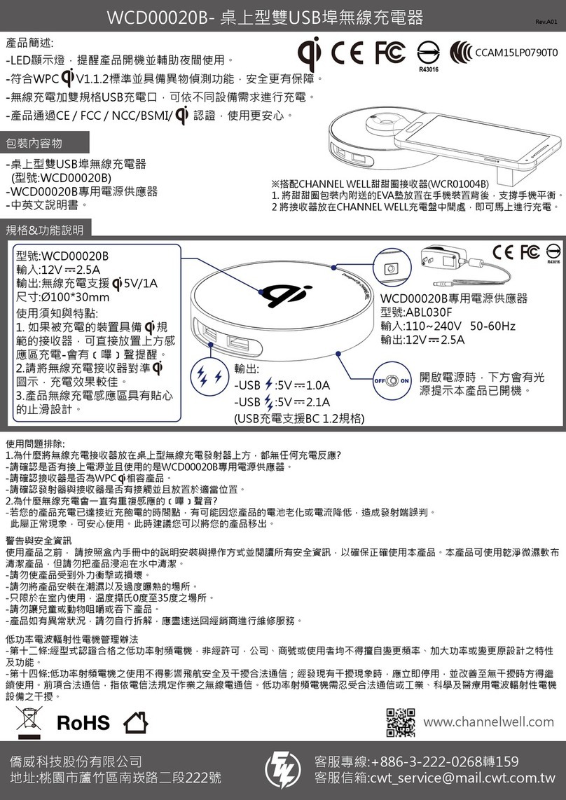
CWT WCD00020B manual

