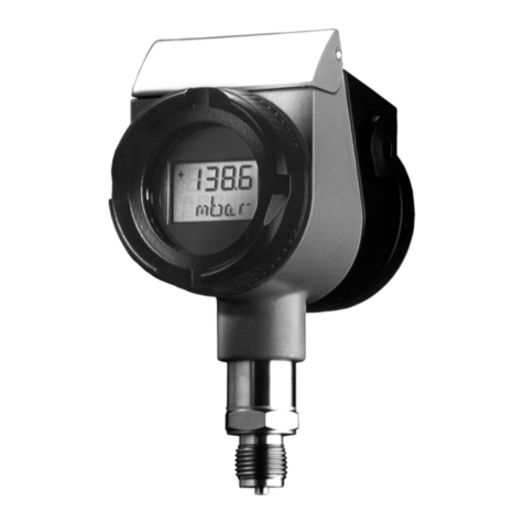
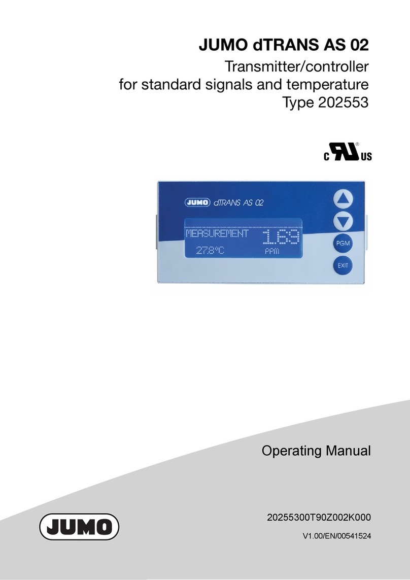
JUMO HART dTRANS p20 Ex d User manual

40302600T90Z001K000
V9.00/EN/00556401/2022-10-31
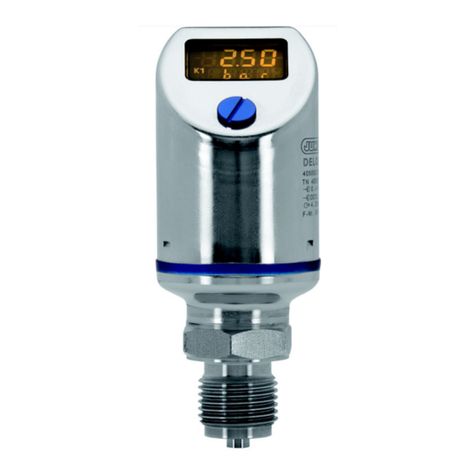
JUMO dTRANS p20 Ex d
Process pressure transmitter
explosion-protected, explosion-proof enclosure
Operating Manual


Contents
Contents
1 Safety information. . . . . . . . . . . . . . . . . . . . . . . . . . . . . . . . . . . . . . . . . . . . 5
1.1 Hazardous materials . . . . . . . . . . . . . . . . . . . . . . . . . . . . . . . . . . . . . . . . . . . . . . . . . . . . . . .5
2 General information . . . . . . . . . . . . . . . . . . . . . . . . . . . . . . . . . . . . . . . . . . 7
2.1 Areas of application . . . . . . . . . . . . . . . . . . . . . . . . . . . . . . . . . . . . . . . . . . . . . . . . . . . . . . .7
2.2 Scope of delivery . . . . . . . . . . . . . . . . . . . . . . . . . . . . . . . . . . . . . . . . . . . . . . . . . . . . . . . . .8
3 Identifying the device version . . . . . . . . . . . . . . . . . . . . . . . . . . . . . . . . . . 11
3.1 Nameplate. . . . . . . . . . . . . . . . . . . . . . . . . . . . . . . . . . . . . . . . . . . . . . . . . . . . . . . . . . . . . . .11
3.2 Order details . . . . . . . . . . . . . . . . . . . . . . . . . . . . . . . . . . . . . . . . . . . . . . . . . . . . . . . . . . . . .12
3.3 Accessories. . . . . . . . . . . . . . . . . . . . . . . . . . . . . . . . . . . . . . . . . . . . . . . . . . . . . . . . . . . . . .14
3.4 Software . . . . . . . . . . . . . . . . . . . . . . . . . . . . . . . . . . . . . . . . . . . . . . . . . . . . . . . . . . . . . . . .14
3.5 Dimensions . . . . . . . . . . . . . . . . . . . . . . . . . . . . . . . . . . . . . . . . . . . . . . . . . . . . . . . . . . . . . .15
3.5.1 Process connections. . . . . . . . . . . . . . . . . . . . . . . . . . . . . . . . . . . . . . . . . . . . . . . . . . . . . . .15
4 Technical data . . . . . . . . . . . . . . . . . . . . . . . . . . . . . . . . . . . . . . . . . . . . . . . 17
4.1 General Information . . . . . . . . . . . . . . . . . . . . . . . . . . . . . . . . . . . . . . . . . . . . . . . . . . . . . . .17
4.2 Input . . . . . . . . . . . . . . . . . . . . . . . . . . . . . . . . . . . . . . . . . . . . . . . . . . . . . . . . . . . . . . . . . . .18
4.3 Output . . . . . . . . . . . . . . . . . . . . . . . . . . . . . . . . . . . . . . . . . . . . . . . . . . . . . . . . . . . . . . . . . .18
4.4 Voltage supply. . . . . . . . . . . . . . . . . . . . . . . . . . . . . . . . . . . . . . . . . . . . . . . . . . . . . . . . . . . .18
4.5 Mechanical features . . . . . . . . . . . . . . . . . . . . . . . . . . . . . . . . . . . . . . . . . . . . . . . . . . . . . . .19
4.6 Environmental influences . . . . . . . . . . . . . . . . . . . . . . . . . . . . . . . . . . . . . . . . . . . . . . . . . . .20
4.7 Accuracy . . . . . . . . . . . . . . . . . . . . . . . . . . . . . . . . . . . . . . . . . . . . . . . . . . . . . . . . . . . . . . . .21
4.8 Approvals and approval marks . . . . . . . . . . . . . . . . . . . . . . . . . . . . . . . . . . . . . . . . . . . . . . .23
5 Mounting . . . . . . . . . . . . . . . . . . . . . . . . . . . . . . . . . . . . . . . . . . . . . . . . . . . 25
5.1 Before mounting . . . . . . . . . . . . . . . . . . . . . . . . . . . . . . . . . . . . . . . . . . . . . . . . . . . . . . . . . .25
5.2 Unscrew the front ring or case lid . . . . . . . . . . . . . . . . . . . . . . . . . . . . . . . . . . . . . . . . . . . . .25
5.3 Rotating the LCD (display) . . . . . . . . . . . . . . . . . . . . . . . . . . . . . . . . . . . . . . . . . . . . . . . . . .26
5.4 Rotating the housing . . . . . . . . . . . . . . . . . . . . . . . . . . . . . . . . . . . . . . . . . . . . . . . . . . . . . . .27
5.5 Pressure connection . . . . . . . . . . . . . . . . . . . . . . . . . . . . . . . . . . . . . . . . . . . . . . . . . . . . . . .28
5.6 Measuring the relative or absolute pressure. . . . . . . . . . . . . . . . . . . . . . . . . . . . . . . . . . . . .29
5.7 Bracket for wall and pipe mounting. . . . . . . . . . . . . . . . . . . . . . . . . . . . . . . . . . . . . . . . . . . .32
5.8 Level measurement with or without a pressure separator . . . . . . . . . . . . . . . . . . . . . . . . . .33
5.8.1 General information for a system with a diaphragm seal . . . . . . . . . . . . . . . . . . . . . . . . . . .33
5.9 Assembly in the explosion area . . . . . . . . . . . . . . . . . . . . . . . . . . . . . . . . . . . . . . . . . . . . . .34
6 Installation . . . . . . . . . . . . . . . . . . . . . . . . . . . . . . . . . . . . . . . . . . . . . . . . . . 35
6.1 Installation notes . . . . . . . . . . . . . . . . . . . . . . . . . . . . . . . . . . . . . . . . . . . . . . . . . . . . . . . . . .35
6.1.1 Connection diagram "Ex" . . . . . . . . . . . . . . . . . . . . . . . . . . . . . . . . . . . . . . . . . . . . . . . . . . .37
6.2 Device with cable gland . . . . . . . . . . . . . . . . . . . . . . . . . . . . . . . . . . . . . . . . . . . . . . . . . . . .38

Contents
7 Operation . . . . . . . . . . . . . . . . . . . . . . . . . . . . . . . . . . . . . . . . . . . . . . . . . . . 41
7.1 Display . . . . . . . . . . . . . . . . . . . . . . . . . . . . . . . . . . . . . . . . . . . . . . . . . . . . . . . . . . . . . . . . .41
7.2 Operation with rotary knob or with setup programm . . . . . . . . . . . . . . . . . . . . . . . . . . . . . . .42
7.3 The level concept . . . . . . . . . . . . . . . . . . . . . . . . . . . . . . . . . . . . . . . . . . . . . . . . . . . . . . . . .43
7.3.1 The display level . . . . . . . . . . . . . . . . . . . . . . . . . . . . . . . . . . . . . . . . . . . . . . . . . . . . . . . . . .44
7.3.2 The parameter level . . . . . . . . . . . . . . . . . . . . . . . . . . . . . . . . . . . . . . . . . . . . . . . . . . . . . . .45
8 Configuration. . . . . . . . . . . . . . . . . . . . . . . . . . . . . . . . . . . . . . . . . . . . . . . . 49
8.1 Data flow diagram . . . . . . . . . . . . . . . . . . . . . . . . . . . . . . . . . . . . . . . . . . . . . . . . . . . . . . . . .49
8.2 Description of the possible configurations . . . . . . . . . . . . . . . . . . . . . . . . . . . . . . . . . . . . . .50
8.3 Level measurement configuration with a pressure specification - recommended (tank emp-
ty, tank full) 54
8.4 Level measurement configuration without a pressure specification with or without a dia-
phragm seal 55
9 Maintenance. . . . . . . . . . . . . . . . . . . . . . . . . . . . . . . . . . . . . . . . . . . . . . . . . 57
9.1 Overcoming errors and malfunctions . . . . . . . . . . . . . . . . . . . . . . . . . . . . . . . . . . . . . . . . . .57
10 HART® 7 specification . . . . . . . . . . . . . . . . . . . . . . . . . . . . . . . . . . . . . . . . 59
10.1 Device identification . . . . . . . . . . . . . . . . . . . . . . . . . . . . . . . . . . . . . . . . . . . . . . . . . . . . . . .59
10.2 Variable codes . . . . . . . . . . . . . . . . . . . . . . . . . . . . . . . . . . . . . . . . . . . . . . . . . . . . . . . . . . .59
10.3 HART® commands . . . . . . . . . . . . . . . . . . . . . . . . . . . . . . . . . . . . . . . . . . . . . . . . . . . . . . . .60
10.4 Burst mode commands . . . . . . . . . . . . . . . . . . . . . . . . . . . . . . . . . . . . . . . . . . . . . . . . . . . . .63
10.5 Performance data . . . . . . . . . . . . . . . . . . . . . . . . . . . . . . . . . . . . . . . . . . . . . . . . . . . . . . . . .64
11 Declaration of conformity. . . . . . . . . . . . . . . . . . . . . . . . . . . . . . . . . . . . . . 65
12 Examination certificate . . . . . . . . . . . . . . . . . . . . . . . . . . . . . . . . . . . . . . . . 69
13 China RoHS . . . . . . . . . . . . . . . . . . . . . . . . . . . . . . . . . . . . . . . . . . . . . . . . . 73

5
1 Safety information
1 Safety informat ion
General
This manual contains information that must be observed in the interest of your own safety and to avoid
material damage. This information is supported by symbols which are used in this manual as indicated.
Please read this manual before starting up the device. Store this manual in a place that is accessible to
all users at all times.
If difficulties occur during startup, please do not intervene in any way that could jeopardize your warranty
rights!
Warning symbols
DANGER!
This symbol indicates that personal injury from electrocution may occur if the appropriate precaution-
ary measures are not taken.
CAUTION!
This symbol in connection with the signal word indicates that material damage or data loss will occur
if the respective precautionary measures are not taken.
Note symbols
NOTE!
This symbol refers to important information about the product, its handling, or additional benefits.
1.1 Hazardous materials
Using hazardous materials as a medium may result in abrasive and corrosive damage to components
of the product that come into contact with the medium. The medium may leak and present a fire hazard
and a risk to health.
Carry out a risk assessment taking into consideration the safety data sheet for the relevant hazardous
substance for mounting, operation, maintenance, cleaning, and disposal:
• Comparison and systematic checking of the durability of the components of the product that come
into contact with the medium and the admissible environmental influences.
• Assessment of the risk to people and the environment.
• Assessment of the fire hazard due to the product materials, the admissible environmental influences,
and the voltage supply.

1 Safety information
6

7
2 General information
DANGER!
The device is suitable for measuring pressure in gases and liquids without solids content.
In the SIL version (functional safety), this device is used in safety-related systems for minimum,
maximum and area monitoring that fulfil the requirements of the series of standards
IEC 61508:2010.
A failure of the device or other devices connected to it, e.g. due to an operating error, can lead to
dangerous malfunctions of the whole plant.
Therefore please also observe the corresponding safety manual from the device series.
NOTE!
Read this operating manual before putting the device into service. Keep the operating manual in a place
that is accessible to all users at all times.
All necessary settings are described in this operating manual. Nevertheless, should problems be en-
countered during startup please do not make any unauthorized manipulations. This could endanger your
rights under the warranty!
Please contact the nearest branch office or the head office.
2.1 Areas of application
General information
The pressure transmitter with HART® interface combines maximum precision with simple operation. It
is used to measure the relative or absolute pressures of gases, vapors, and liquids. The integrated LCD
display shows the measured values and device data.
The pressure transmitter with flameproof enclosure can be installed up until zone 0. The housing and
sensors are manufactured from high-grade stainless steel. Various flush-mounted process connections
are available for applications with hygienic requirements, including PEKA connection system (see data
sheet 409711).
Diaphragm seals can also be connected for specific process technology applications (see data sheets
409772 to 409784).
The transmitter is programmable and therefore readily adaptable to a variety of different measurement
tasks. An easy-to-use setup program is available as an accessory to enable operation via the interfaces.
A rotary knob makes manual operation on-site very convenient and quick.
The pressure transmitter with 4 to 20 mA and HART® protocol was evaluated with regard to functional
safety and is certified by exida according to IEC 61508/-1/-2/-3. These measuring devices are suitable
for monitoring process level and process pressure up to SIL2. Further details can be found in the Safety
Manual.
Use in „Ex-area“
The device is permitted for use in the „Ex-area“. The device is flameproof enclosed and ca be mounted
in Zone 1!
Functional safety use
In the SIL version, the device is permitted for use according to IEC 61508 if it has a corresponding iden-
tification marking on the nameplate.

2 General information
8
CAUTION!
The device‘s membranes must not be damaged at the process connection!
Do not insert any objects into the drilled holes of the pressure connections!
The device must be sent back if there is damage to the housing or membrane!
2.2 Scope of delivery
Operating Manual
The operating manual describe the mounting, the electrical connection, the startup and operation of the
device.
Safety manual (option)
The safety manual describes the safe application with the installation according to IEC 61508.
Calibration certificate
The device is supplied with a calibration certificate and a setup print-out.
These documents contain information about the set parameters and/or the measured parameters for the
respective device.
If the calibration certificate is lost or if you need another copy, the calibration certificate can be requested
from the manufacturer by specifying the device's F number (see nameplate). You will find the supplier's
address on the back cover of the manual.
Setup program (option)
The setup program is available as an option: part no. 00537577
All the device's parameters can be conveniently checked and adjusted using the setup program - there
are also additional functions, e.g.:
• Recording the measured values
• Graphical view of temperature and pressure
• Detailed diagnostic messages
• Display of the complete order code and the device configuration (for follow-up orders)
The setup program accesses the device via
• the JUMO interface (standard) or
• the HART® interface (optional)

9
2 General information
DANGER!
The JUMO interface must not be used in the Ex-area!
The device may only be operated using the rotary knob or the HART® interface!
PC interface cable (option)
Available as an accessory: PC interface cable with USB/TTL converter and two adapters (USB transmit-
ter cable), part no. 00456352.
The device can be connected to a PC's USB port via the JUMO interface with the PC interface cable.
HART® modem (option)
Available as an accessory: HART® modem for USB, part no. 00443447.
The device can be connected to a PC's USB® port via the HART® interface with the HART® modem.
Diaphragm seal (option)
Available as an accessory: see data sheets 409770 to 409786.
Diaphragm seals are used for adjusting to particular applications if conventional pressure connections
cannot be used.
CAUTION!
Diaphragm seals are installed by default and must not be removed from the device!

2 General information
10

11
3 Identifying the device version
3 Identi fying t he device version
3.1 Nameplate
Housing
Sample identification marking on the device housing.
Date of manufacture
The date of manufacture (year and calendar week) of the device is encoded in the manufacturing num-
ber. The numbers 12 to 15 identify the year of manufacture and the calendar week.
Sensor unit
Identification marking on the device's sensor housing:
(1) Part number (2) Fabrication number
(3) Output signal (4) Voltage supply
(5) Nominal measuring range (6) Werkseinstellung Nennmessbereich
(7) Type (8) SIL-Ausführung
(8)
(2)
(7)
(6)
(5)
(4)
(3)
(1)
(1) Part number
(2) Nominal measuring range
(3) Fabrication number
(1)
(2)
(3)

3 Identifying the device version
12
3.2 Order details
(1) Basic type
403026 JUMO dTRANS p20 Ex d - process pressure transmitter with flameproof enclosure
(2) Basic type extension
0 None
2SIL
a
9 Special version
(3) Display
0 None
1 With display
(4) Operation
0 None
1 With control knob
(5) Input – nominal measuring range
450 -600 to +600 mbar relative pressure
473 -1 to +2.5 bar relative pressure
513 -1 to +4 bar relative pressure
472 -1 to +10 bar relative pressure
514 -1 to +25 bar relative pressure
515 -1 to +100 bar relative pressureb
508 -1 to +250 bar relative pressurec
516 -1 to +600 bar relative pressurec
487 0 to 0.6 bar absolute pressure
490 0 to 2.5 bar absolute pressure
491 0 to 4 bar absolute pressure
493 0 to 10 bar absolute pressure
495 0 to 25 bar absolute pressure
507 0 to 100 bar absolute pressure
(6) Output
410 4 to 20 mA, two-wire with HART® protocol
(7) Process connection
504 G 1/2 according to DIN EN 837
512 1/2-14 NPT according to DIN 837
564 1/2-14 NPT internal
571 G 3/4 front-flush according to DIN EN ISO 228-1
583 M20 (× 1.5) with pin
604 Taper socket with grooved union nut DN 25 according to DIN 11851 (dairy pipe fitting)
606 Taper socket with grooved union nut DN 40 according to DIN 11851 (dairy pipe fitting)
613 Clamp connection DN 25/32/40 according to DIN32676
616 Clamp connection DN 50 according to DIN 32676/2" ISO 2852
652 Tank connection with grooved union nut DN 25
997 JUMO PEKA hygienic process connection
998 Diaphragm seal process connection
(8) Process connection material
20 CrNi (stainless steel)

13
3 Identifying the device version
82 NiMod
(9) Measuring system, filling medium
00 Withoute
01 Silicon oil
(10) Extra codes
000 None
100 Customer-specific factory settingf
226 GOST/EAC approvalg
452 Wetted, electrolytically polished parts
591 Choke in the pressure channel
624 Oil and grease free
630 Enlarged pressure channel
634 TAG number
635 NACE manufacturer's declarationh
681 Expanded admissible ambient temperature
aOnly available with display 1. Not available with input 508 and 516 and also extra code 681.
bNot available with process connection 604, 606, 613, 616.
cNot available with process connection 571, 604, 606, 613, 616, 997.
dNot available with input 450, 573, 513, 472, 487, 490, 491, 493.
eOnly available with input 508, 516.
fPlease specify the setting you want in plain text. For default setting see “Accuracy” section in the data sheet.
gAvailable upon request.
hOnly available with process connection 512, 565 and process connection material 82. Not available with input 450,
487.
(1) (2) (3) (4) (5) (6) (7) (8) (9) (10)
Order code /------- /
Order example 403026 / 0 - 1 - 1 - 514 - 410 - 504 - 20 - 01 / 000

3 Identifying the device version
14
3.3 Accessories
3.4 Software
Designation Part no.
PC interface with USB/TTL convertera00456352
HART® modem USBb00443447
Measuring device holder for wall and 2" pipe 00597711
Designation Data sheet
Valve manifolds 409706
Diaphragm seal with dairy pipe fitting DIN 11851 409772
Diaphragm seal with clamp connection 409774
Druckmittler mit DRD-Flansch oder VARIVENT®-Stutzen 409776
Diaphragm seal with ISS/SMS/RJT socket and (grooved) union nut 409778
Membrane diaphragm seal 4MDV-10 409780
Diaphragm seal with screw-in thread DIN ISO 228/1 or ANSI B1.201 409782
Diaphragm seal with flange connection DIN EN 1092-1 with sealing strip form B1 409784
Diaphragm seal with flange connection according to ANSI B 16.5 with sealing strip form RF 409786
aThe PC interface cable is the connection between the JUMO interface of the differential pressure transmitter and
the USB interface of a PC.
bThe HART® modem is the connection between the HART® interface of the differential pressure transmitter and
the USB interface of a PC.
Description Part no.
JUMO setup dTRANS p20 series 00537577
Device Type Manager (DTM), JUMO dTRANS p20 00738288

15
3 Identifying the device version
3.5 Dimensions
3.5.1 Process connections
A Kabelverschraubung M20 × 1,5
145
116
72
116
Ø 73
A
504 512 564
G 1/2 1/2-14 NPT 1/2-14 NPT internal
G 1/2
20
30.5
1/2-14 NPT
30.5
20
SW 27
23.5
1/2-14 NPT
571 583
G 3/4 M20 (× 1.5) with pin
32
16
SW 32
G 3/4
M20x1,5
30.5
20

3 Identifying the device version
16
Dimensions of the process connections 604, 606, 613, and 616
604 and 606 613 and 616
Taper socket with grooved union nut according to DIN 11851 Clamp according to DIN 32676
L1
L2
15
D2
D1
652 997
Tank connection with grooved
union nut DN 25
JUMO PEKA
RD52 x1/6
35
45
55
63
21
31
31.5
SW 27
11
ConnectionDND1D2D3 D4L1L2
604 25 Ø 44 Ø 35 Rd 52 × 1/6“ Ø 63 15 21
606 40 Ø 56 Ø 48 Rd 65 × 1/6“ Ø 78
613 25 Ø 43,5 Ø 50.5
616 50 Ø 56,5 Ø 64

17
4 Technical data
4 Technical d ata
4.1 General Information
Reference conditions DIN EN 60770 and DIN EN 61298
Ambient temperature 22 °C ±5 K
Air pressure 1000 hPa (±25 hPa)
Voltage supply DC 24 V
Burden 50 Ω
Sensor system Silicon sensor with stainless steel separating diaphragm
Pressure transfer medium
For measuring system filling medi-
um 0
Without transfer medium
For measuring system filling medi-
um 1
Silicon oil, FDA compliant
Admissible load changes > 10 million
Position
Mounting position Any
Calibration position Device upright, process connection at the bottom
Zero offset depending on position A zero offset is possible on-site or via setup.
DisplayaLCD, two-line with bar graph
Alignment Display unit rotatable in 90° steps
Housing rotatable ±160°
Size Display 22 × 35 mm, font size 7 mm/5 digits
Color Black
Portrayable measuring units
Input pressure mH2O, inH2O, inHg, ftH2O, mmH2O, mmHg, psi, bar, mbar, kg/cm2, kPa, Torr,
MPa
Measured value % or scaled with freely adjustable measuring unit
Output current mA
Sensor temperature °C, °F
Additional display data Minimum pressure, maximum pressure, error, overrange, underrange, operat-
ing hours, device parameters
Operation
On-site With rotary knob and LCD
Setup program Via interface
Interface
Standard JUMO interfaceb
For output 410 (4to20mA with
HART®)
JUMO interfaceb and HART® interface
aoptional; SIL version only available with display
bThe JUMO interface may not be used in a potentially explosive area! In such a case the device can be operated
via the rotary knob or the HART® interface.

4 Technical data
18
4.2 Input
4.3 Output
4.4 Voltage supply
Relative pressure
Nominal measuring
range
-600 to +600 mbar -1 to +2.5 bar -1 to +4 bar -1 to +10 bar
Overload capability 6 bar 15 bar 30 bar 60 bar
Burst pressure 12 bar 30 bar 60 bar 100 bar
Relative pressure
Nominal measuring
range
-1 to +25 bar -1 to +100 bar -1 to +250 bar -1 to +600 bar
Overload capability 150 bar 300 bar 600 bar 1200 bar
Burst pressure 250 bar 400 bar 700 bar 2000 bar
Absolute pressure
Nominal measuring
range
0 to 0.6 bar 0 to 2.5 bar 0 to 4 bar 0 to 10 bar 0 to 25 bar 0 to 100 bar
Overload capability 6 bar 15 bar 30 bar 60 bar 150 bar 300 bar
Burst pressure 12 bar 30 bar 60 bar 100 bar 250 bar 400 bar
Analog output
For output 410
(4 to 20 mA with HART®)
4 to 20 mA, two-wire with HART® version 7
Jump response time T60 ≤ 190 ms without attenuation
Attenuation Adjustable 0 to 100 s
Burden
For output 410
(4 to 20 mA with HART®)
Burden ≤ (UB-12 V) ÷ 0.022 A; additional: min. 250 Ω, max. 1100 Ω
Voltage supply DC 12 to 36 V

19
4 Technical data
4.5 Mechanical features
Process connection
Materials
For process connection 20
(stainless steel)
316 L for front-flush process connections
Otherwise 316 Ti
For process connection 82
(HASTELLOY®)
2.4819 NiMo
Surface Ra ≤ 0.8 µm
Process seal
Process connection 571
G 3/4 front-flush) and
process connection 652
(tank connection with grooved
union nut)
FPM
For process connection 997
(JUMO PEKA)
FDA compliant: FPM, VMQ, EPDM as an option, see data sheet 409711
For all other process connections No seal
Measuring membranes
For material lid 20 (stainless steel) 1.4542 for -1 to +250 bar relative pressure (measuring range 508) and
-1 to +600 bar relative pressure (measuring range 516)
Otherwise 316 L
For material lid 82 (plastic) 2.4819 NiMo
Surface Ra ≤ 0.8 µm
Housing
Housing material Precision casting 1.4408
Cover material Precision casting 1.4408, seal FPM
Material of control knob
For operation 0
(without control knob)
-
For operation 1
(with control knob)
PA
Explosion protection EC type examination certificate SEV 10 ATEX 0127 X
II 1/2G Ex d IIC T6 ... T4 Ga/Gb
II 2D Ex tb IIIC T105 °C Db
Weight Approximately 1.6 kg

4 Technical data
20
4.6 Environmental influences
Admissible temperatures
Operation Version Tempera-
ture class
Maximum
medium
temperature
Ambient
temperaturea
Expanded ambi-
ent temperature
(extra code 681)a,
b, c
II 1/2G Ex d T6 70 °C -40 to +60 °C -50 to +60 °C
T5 85°C -40to+70°C -50to+70°C
T4 115°C -40to+85°C -50to+85°C
II 2D Ex tb T105 °C 100 °C -40 to +85 °C -50 to +85 °C
Storage -40 to +85 °C
Admissible humidity
Operation 100 % including condensation on the device outer case
Storage 90 % without condensation
Admissible mechanical load
Vibration strength 2 g, 10 to 2000 Hz according to DIN EN 60770-3
Shock resistance 15 g for 6 ms according to IEC 60068-2-27
Electromagnetic compatibility According to EN 61326
Interference emission Class Bd
Interference immunity Industry
Protection type IP66 according to DIN EN 60529
aUnder -20 °C limited function: stationary use, increased danger of cable break, display without function; under -
30 °C operation of the device not possible.
bIn the range from -40 to -50 °C the device must be permanently in operation. Furthermore, the lid with the device
inspection glass must additionally be protected against mechanical impact and shock effects. Please contact JUMO
for further details.
cWithout SIL
dThe product is suitable for industrial use as well as for households and small businesses.
Table of contents
Other JUMO Transmitter manuals

JUMO
JUMO B 707025.0 User manual

JUMO
JUMO JUMO dTRANS p20 DELTA User manual

JUMO
JUMO CTI-750 User manual

JUMO
JUMO Wtrans B User manual

JUMO
JUMO JUMO dTRANS p20 DELTA User manual

JUMO
JUMO 907021/10 User manual

JUMO
JUMO dTRANS AS 02 User manual

JUMO
JUMO dTRANS p02 User manual

JUMO
JUMO Wtrans p User manual

JUMO
JUMO dTRANS T03 J User manual

JUMO
JUMO dTRANS T05 User manual

JUMO
JUMO dTRANS T06 User manual

JUMO
JUMO dTRANS T02 PCP User manual

JUMO
JUMO SIRAS P21 DP User manual

JUMO
JUMO dTRANS T08 01 User manual

JUMO
JUMO dTRANS T09 DS User manual

JUMO
JUMO CTI-500 User manual

JUMO
JUMO 404304 Series User manual

JUMO
JUMO dTRANS T07 Reference guide

JUMO
JUMO 4AP-30 User manual