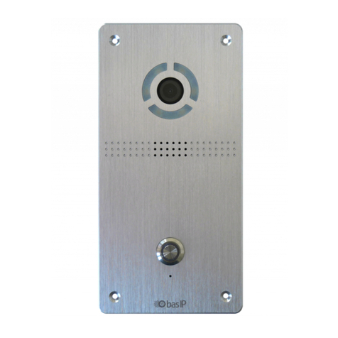
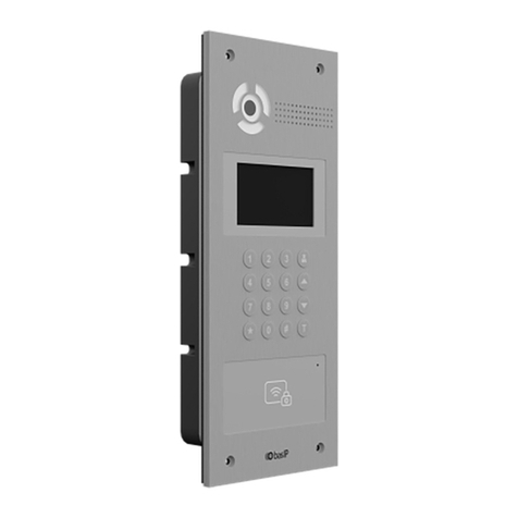
basIP AV-01KD User manual

AV-01KD
AV-01KD
Exported on 08/12/2019

– 2
Table of Contents
Device description................................................................................................ 5
Appearance.....................................................................................................................................5
Technical parameters.......................................................................................... 6
Main features ................................................................................................................................. 6
Funcitonal capabilities ............................................................................................................... 6
Configuration through WEB interface...........................................................7
Login ..................................................................................................................................................7
Main ....................................................................................................................................................7
Network info ...................................................................................................................................................................8
Network ........................................................................................................................................... 9
Custom NTP....................................................................................................................................................................9
Panel ................................................................................................................................................. 9
Apartment settings ......................................................................................................................................................9
SIP settings....................................................................................................................................................................10
Call settings.................................................................................................................................................................... 11
Device settings ............................................................................................................................................................ 12
Access ............................................................................................................................................. 12
Common settings........................................................................................................................................................ 13
Locks management.................................................................................................................................................... 13
Open lock....................................................................................................................................................................... 14
Additional settings ..................................................................................................................................................... 14
Identifiers ....................................................................................................................................................................... 14
New identifier ............................................................................................................................................................... 15
Forward ..........................................................................................................................................16
Forward settings......................................................................................................................................................... 16
New forward queue ................................................................................................................................................... 16
Advanced....................................................................................................................................... 18
System ............................................................................................................................................18
Settings........................................................................................................................................................................... 19
Device language.......................................................................................................................................................... 19
Reboot ............................................................................................................................................................................ 19

– 3
Installation and connection.............................................................................20
Completness check of the product ....................................................................................20
Electrical connection................................................................................................................20
Mechanical mounting ................................................................................................................ 21
Connection of additional modules...................................................................................... 23
Usage of the device ...........................................................................................24
Getting the RTSP stream from the camera of the outdoor panel ..........................24

Device description– 5
Device description
AV-01K is an individual call panel with a code set. This panel can operate in two modes -
individual and multi apartment. In the individual mode, the keypad panel serves as a keypad for
opening the lock, and using the direct call button, you can communicate with the desired
monitor.
Appearance

Technical parameters– 6
Technical parameters
Main features
Panel Type:Individual
Display:No
Camera:1/4 ", adjustable camera angle by 15 °
Viewing angle:Horizontal 100 °, vertical 52 °
Camera resolution:1 MP
Output video:720p (1280x720), H.264 Main Profile
Night backlight:6 LEDs
Minimum illumination:0.01 LuX
Protection class:IP65
Temperature range:-40 - +65 ° С
Power consumption:5.5 W, standby 2.5 W
Power supply:+ 12 volts
Body:Metallic
Color solution:titanium gray
Dimentions for installation:104 × 180 × 60 mm
The size of the panel itself:115 × 190 × 45 mm
Installation Type:Flush, surface with BR-AV bracket
Funcitonal capabilities
Interface:Russian / English, WEB – interface
Opening the lock:From the monitor, via the BAS-IP Intercom application
ACS Integration:No
Shortcut buttons:1 mechanical call button, keypad
Number of call melodies:4 polyphonic melodies
Authentication:Separate password for settings, WEB – interface
Talk mode:Duplex
Optional:SIP P2P, Built-in Relay

Configuration through WEB interface– 7
Configuration through WEB interface
•Login(see page 7)
•Main(see page 7)
•Network(see page 9)
•Panel(see page 9)
•Access(see page 12)
•Forward(see page 16)
•Advanced(see page 18)
•System(see page 18)
Login
To configure the call panel remotely via the WEB interface, you need to connect to it with an
Internet browser on your PC. The panel must be connected in the same network segment as the
PC from which it is planned to perform the configuration.
To find the device in the LAN it is required to use Remote search and upgrade tool.
In the Internet browser, in the address entry box, you must enter the IP address of the panel,
after which the user name and password entry window will appear.
Username to enter the settings: admin.
The password required for entry corresponds to the password for access to the settings of the
call panel and is the installer password (default password: 123456).
Main
After successful authorization, the following interface will be displayed:

Configuration through WEB interface– 8
Device info
Framework:A version of the framework.
Launcher:A version of the launcher.
Network info
DHCP:Current DHCP status.
IP адрес:Current IP address of the device.
Subnet mask:Used subnet mask.
Gateway:Gateway address.
DNS server:DNS server address.
MAC address:Physical address of the device.

Configuration through WEB interface– 9
Network
DHCP: Enable/disable the automatic retrieval of network settings.
IP: Panel IP address.
Mask: Subnet mask.
Gateway: The main gateway.
DNS: DNS server address.
Custom NTP
Current device date/time:Shows the current device's date and time.
URL:Field to enter custom NTP server address.
Timezone:Choose used timezone.
Panel
Apartment settings
By default, the call panel can have a static IP address 192.168.1.90 or 192.168.1.91.

Configuration through WEB interface– 10
Mode: Selection of the panel operation mode.
Building: Building number.
Unit:Unit number.
Floor: Floor number.
Apartment.: Apartment number.
No: Order number of the call panel.
SIP settings
To work in the multi-apartment panel mode, with the ability to dial an apartment using
the keyboard, you need to select the "Unit Panel". In this mode, the call button will work
as a concierge call button.
To work in the individual panel mode, with the ability to dial the lock opening code
using the keyboard, you must select the "Personal Panel". In this mode, the call button
will work for its intended purpose. The building number, front door, floor, and
apartment must correspond to the internal monitor, which will receive an incoming call
from this call panel.
If you have several call panels that have one logical address, then in the "No." field
specify the value 2, 3, 4, 5, etc., up to 9.

Configuration through WEB interface– 11
Enable/Disable:Enable/disable SIP registration.
Proxy:A proxy SIP server that can be represented by both an IP address and a domain name.
Server:SIP server address.
STUN IP:STUN server address.
STUN port:The port of the STUN server.
Password:Password of SIP number.
Automatic re-registration: Re-register the device on the SIP server.
Re-registration interval: Input field for the time interval in seconds, after which the device will be
re-registered on the SIP server.
Call settings
Data format:
Before the proxy address, you must specify "sip:".
Data format:
Сan be represented by both an IP address and a domain name.
Example:
stun.l.google.com.
Example:
For google STUN server 19302 port is used.

Configuration through WEB interface– 12
The maximum time for calling: The time interval after which the panel automatically ends an
outgoing call if there is no answer.
Maximum talk time: The time interval after which the panel automatically ends the outgoing
conversation.
Device settings
Video quality: Select your preferred video resolution.
RTP data profile: Select your preferred RTP data profile.
Volume Level: Adjusts the speaker volume of the panel.
Access
In this menu, you can set general control parameters of the access control system, access rules,
and identifiers.

Configuration through WEB interface– 13
Common settings
Master card: Master card number.
Use master code: Enable/disable using master code to open the lock.
Master code: The code entered on the keypad for opening the lock.
Locks management
Lock open time (s): Time for which the panel relay contacts are closed or open.
Lock open delay: Time after which the contacts of the panel's relay will close or open.
When using the control module with two locks SH-42, when entering the master code
on the panel, both locks will open.
Registering access cards via web interface
Enter 0 in the “Master card” field and click the “Apply” button.
Next, bring the master card, necessary for the registration, to the panel reader area -
the signal "BEEP" will sound, which means that the master card has been successfully
registered. After that, you need to put this card again to enter the card-issuing mode.
After that, in the area of the panel reader hold the user cards in turn. After each user
card, the “BEEP” signal will sound, which means the successful registration of the raised
card.
The time between adding cards should not exceed 10 seconds.

Configuration through WEB interface– 14
Keep the lock open, if there is no SIP registration: Function to automatically open the lock if SIP
registration on the panel is lost.
No Sip registration time: Time period after which the lock begins to openif SIP registration on
the panel is lost.
Open lock
Lock #1, Lock #2
Open lock: The function of opening the selected lock from the panel WEB interface.
Additional settings
Monitor secure mode: Turns off the alarm on the internal monitor when you bring up a card that
is connected to the logical address of this monitor.
Identifiers
This menu displays a table of identifiers and access codes added to the panel memory.

Configuration through WEB interface– 15
New identifier
After clicking on the "New identifier" button, the following interface will appear:
Identifier number: Number of identifier in decimal format.
Building:
Unit:
building number
0001-9999

Configuration through WEB interface– 16
Floor:
Room:
Forward
This section is used to substitute numbers by means of the panel when making calls to internal
monitors when there is no monitor or it is turned off, or to any given SIP number.
Forward settings
Mode: Mode of the forwarding.
All at once - the call is made to all numbers simultaneously.
One by one - the call is made to the numbers in turn with a delay of 20 seconds.
New forward queue
Unit number
00-99
Floor number
00-99
Room number
01-99

Configuration through WEB interface– 17
After clicking on the "New Forward" button, the following interface will be displayed:
Apartment number: Number dialed on the panel's keypad.
Forward Number: The direction in which the call will be made when you enter the corresponding
number on the keypad. It can be used both for calls within the LAN via P2P, and for SIP calls.
Input format for internal calls
192.168.1.65 is the IP address of the called SIP client (in the case of using a softphone,
the IP address of the device where the softphone is installed).
Call to SP-02:
sip:192.168.1.99, where 192.168.1.99 is the IP address of the called handset.
Input format for SIP calls
sip.bas-ip.com is the address of the SIP server, which can be specified either by the IP
address or by the domain name.

Configuration through WEB interface– 18
Advanced
RTSP feed:Function to view additional IP cameras during a call (up to 4 streams). This feature is
available for v4 monitors and any other SIP devices with a keyboard.
Url: Address of the RTSP stream displayed during the call.
System
In this section, backup and restoration of the panel settings, software update, language change,
and software reboot are performed.
During a call, it is possible to switch between streams by pressing keys 1 through 5. The
key "1" corresponds to the stream of the camera of the call panel, the keys from "2" to
"5" - to additionally added streams (transmission is done by DTMF RFC2833).
Example
rtsp://admin:[email protected]:8554/ch01

Configuration through WEB interface– 19
Settings
Choose file:Selecting the panel configuration file from the PC file system.
Set default settings:Reset all panel settings to factory defaults.
Backup all settings:Save and export configuration files.
Device language
Choosing the language of the device.
Reboot
Reboot:Soft reset of the panel.

Installation and connection– 20
Installation and connection
This page describes the process of installation and connection of the outdoor panel.
•Completness check of the product(see page 20)
•Electrical connection(see page 20)
•Mechanical mounting(see page 21)
•Connection of additional modules(see page 23)
Completness check of the product
Before installation of the outdoor panel, it is necessary to check that it is complete and all
components are available.
Outdoor panel kit includes:
Outdoor panel 1pc
Flush mounting bracket 1pc
Installation manual 1pc
Set of wires with connectors for connection of power supply, lock, and
additional modules
1pc
Set of end-caps for connections 1pc
Set screws with a wrench 1pc
Electrical connection
After verifying whether a device is complete, you can switch to the connection.
For connection you will need:
• An Ethernet UTP CAT5 or higher cable connected to a network switch/router.
• Power supply at + 12V, 2 amps.
• Wires must be brought for connecting the lock and additional modules (optional).
1. Connection scheme of electromechanical lock using external power supply for panel and the
lock.
Cable length recommendations
The maximum length of the UTP CAT5 cable segment should not exceed 100 meters,
according to the IEEE 802.3 standard.
You can connect any type of electromechanical or electromagnetic lockfor which
the switched current does not exceed 5 Amps.
Table of contents
Other basIP Intercom System manuals
basIP
basIP AZ-07LL User manual
basIP
basIP AA-07FB User manual
basIP
basIP AV-08FB User manual
basIP
basIP AA-07FB User manual
basIP
basIP BI-02FB User manual
basIP
basIP AA-14FBS User manual

basIP
basIP AA-07BD User manual
basIP
basIP AV-04AFD User manual
basIP
basIP AV-03BD User manual
basIP
basIP AQ-07LA User manual
basIP
basIP AV-04SD User manual
basIP
basIP AT-10 User manual
basIP
basIP AU-04LA User manual
basIP
basIP SP-03 User manual
basIP
basIP AV-03D User manual
basIP
basIP AV-01 Instruction sheet
basIP
basIP AA-14FB User manual
basIP
basIP AA-07FB User manual
basIP
basIP AA-14FBS User manual
basIP
basIP AA-12FB User manual

