Table of Contents
List of Illustrations
List of Tables
i
Paragraph Title Page
SECTION 1 GENERAL INFORMATION
1-1 Purpose.......................................................................................................1-1
1-2 General Description.....................................................................................1-1
1-3 Specifications..............................................................................................1-1
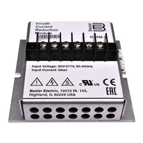
1-4 Spike Suppresson Module ..........................................................................1-2
SECTION 2 PRINCIPLES OF OPERATION
2-1 Block Diagram Theory of Operation............................................................2-1
SECTION 3 INSTALLATION INSTRUCTIONS
3-1 Mounting......................................................................................................3-1
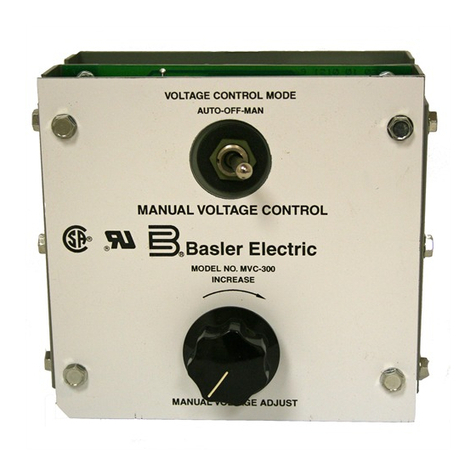
a. Manual Voltage Control Module Mounting ...........................................3-1
b. Spike Suppression Module Mounting...................................................3-2
3-2 Interconnection............................................................................................3-3
a. General.................................................................................................3-3
b. Input Power..........................................................................................3-3
c. Output (Field) Voltage ..........................................................................3-3
d. Frequency Selection.............................................................................3-3
e. MANUAL ADJUST Control...................................................................3-3
SECTION 4 OPERATON INSTRUCTIONS
4-1 Operation.....................................................................................................4-1
4-2 Operational Test..........................................................................................4-1
SECTION 5 MAINTENANCE AND TROUBLESHOOTING
5-1 Preventive Maintenance..............................................................................5-1
5-2 Troubleshooting...........................................................................................5-1
5-3 Corrective Action.........................................................................................5-1
5-4 Warranty and Repair Service......................................................................5-1
Figure Title Page
2-1 MVC 236 Block Diagram......................................................................2-1
3-1 MVC 236 Outline Drawing....................................................................3-1
3-2 Manual Voltage Adjust Rheostat..........................................................3-2
3-3 Spike Suppression Module Outline Drawing........................................3-2
3-4 Typical MVC 236 Interconnection ........................................................3-4
3-5 MVC 236 Interconnection with Nullmeter Circuit..................................3-5
4-1 MVC 236 Operational Test...................................................................4-2
5-1 Troubleshooting....................................................................................5-2
Table Title Page
1-1 Electrical Specifications........................................................................1-1
1-2 Physical Specifications.........................................................................1-2
5-1 Recommended Spare Parts List ..........................................................5-1


