Bastl KASTLE v 1.5 User manual

INSTRUCTIONS Kastle is a mini modular synth and as in every
modular synth the sounds are programmed by connecting outputs to inputs. Outputs
are labeled by a silver outline around the patch points. Inputs don‘t have the silver
outline. Feel free to also connect inputs with inputs and outputs with outputs. Nothing
bad will happen. And sometimes something interesting can happen with strange
connections!
0 Find a microUSB cable or go to your nearest store and buy 3 AA batteries. Youcan
catch Pokemons on the way, though you don‘t have to, but the important thing is that
on average you will burn 50 calories. Also, not shipping the batteries to you from us is
environmentally friendly.
Connect the USB cable to a powered 5V USB socket or insert the batteries to the
battery compartment the right way - as indicated on the battery holder.
Flip the power switch to the USB or BATT position based on which power source you
are using. There is a LED close to the LFO RATE knob which should light up. Ifitdoesn‘t
it means the USB socket is not powered or you connected the batteries in a wrong
way or they are completely depleted.
1 Use the OUT jack to connect your headphones or an audio cable from your
speaker system. The main output of the complex oscillator is routed to the OUT jack.
2 Turn the OSC PITCH knob to adjust the PITCH of the main oscillator. Amodulation
signal can be connected to the PITCH MOD socket and the PITCH MOD knob controls
the amount of the modulation.
3 Turn the OSC TIMBRE knob to adjust the PITCH of the modulating oscillator.
Amodulation signal can be connected to the TIMBRE MOD socket and the TIMBRE
MOD knob sets the amount of the modulation.
4 Turn the WAVESHAPE knob to adjust the 3rd parameter of the sound. Amodulation
signal can be connected to the WAVESHAPE socket to modulate this parameter. The
WAVESHAPE also sets the pulse width of the OSC PULSE output.
5 This patch point on the device can be either used as another signal for your patch
or when any other output is connected to this output it will be passively mixed with
the oscillator output and will go to the OUT jack. This is most useful for adding more
power by connecting the SECONDARY OSC OUT.
6 The SECONDARY OSC OUT provides alternative waveform based on the second-
ary modulating oscillator and the waveform can be adjusted by the WAVESHAPE
parameter. It can be either used to modulate parameters within the Kastle synth or
patched to the OSC OUT socket to mix with the main waveform or it can be output
separately via the I/O jack.
7 The MODE socket lets you select the synthesis mode. The synthesis mode affects
both the OSC OUT and the SECONDARY OSC OUT.
○When nothing is connected the synthesis mode at OSC OUT is phase modulation
and at SECONDARY OSC OUT is phase distortion.
○ When a modulation signal plugged into this jack is high (or just patched to “+”
socket) the synthesis mode becomes track & hold modulation on the OSC OUT and
formant synthesis on the SECONDARY OSC OUT.
○ When the signal connected here is low (or just patched to “–” socket) you are
indual noise mode with more tonal character at the SECONDARY OSC OUT.
See the Synthesis Types section for more information.
8 To set the MODE socket statically to specific synth mode use the low = ”–” or high
= ”+” patch sockets. These patch points can be also useful to set the BIT IN pin. “+”
can be used to offset any modulation signal and “–” connects directly to ground so it
can be used to connect grounds between several instruments.
9 The LFO RATE sets the speed of the modulation. The modulation is displayed by
an LED close to the LFO RATE knob. A modulation signal can be connected to the
RATE MOD socket and the RATE MOD knob sets the amount of the modulation. This is
especially useful when creating more complex modulation curves. See Tips & Tricks
section for more info.
10 The LFO TRIANGLE socket outputs simple triangle waveform, but it can be
altered by modulating the LFO RATE or triggering the LFO RST to get some complex
modulation shapes.
11 The LFO PULSE socket outputs PULSE wave in sync with the TRIANGLE wave.
When the TRIANGLE wave is rising the PULSE output is high and when it is falling the
output is low. This signal can be used for synchronising external equipment.
12 The LFO RST resets the phase of the LFO to the highest point of the triangle and
then the triangle begins to fall. This is very useful for creating complex modulation
curves or for synchronising with external clock.
13 The STEPPED generator is inspired by the Rungler circuit by Rob Hordijk. It can
produce 8 different voltages. It generates new voltage twice per period of the LFO
(every time the direction changes from rising to falling). The voltage is based on the
current state of 3 bits of internal binary 8 bit shift register. The shift register is shifted
with every new voltage generated. When this happens - based on the signal at the BIT
IN socket - the new bit arriving to the shift register remains the same (BIT IN is low), is
inverted (BIT IN is not connected) or is generated randomly (BIT IN is high). It means
that when BIT IN is not connected the STEPPED output generates a 16 step pattern.
When it is low it generates an 8 step pattern. When it is high it keeps generating
a random pattern and when it is altering it generates a semi-random pattern. The
STEPPED output is very useful for modulating every parameter in the Kastle synth
orany external device with the I/O port.
14 The I/O CV port enables you to connect up to 2 modulation/audio/clock
signals from Kastle to external gear or to connect any external signal to modulate
the Kastle synth. The signals are output with a stereo jack and the patch points
L and R connect either to the left or right channel. To use both channels with a
modular synth you can use stereo to mono splitter adapter or you can just use one
channel (L) with a mono cable connected to the I/O jack. When connecting external
modulation to Kastle please note that the signal will be rectified and Kastle will
respond only to signals 0-5V.
OSC OUT
LFO
RST
BIT IN
STEPPED
MODE
L R
OSC PITCH
LFO RATE
RATE MOD
TIMBRE MOD OSC TIMBRE
WAVESHAPE
PITCH MOD
OUT
I / O
I / O
LFO
LFO
OSC
USB
USB POWER
BATT
22
3 3
9
9
9
8
7
2
312
13
10
11
6
4
14 5
114 0
0
FEATURES v1.5
©complex oscillator
©3 synthesis modes on the main output: phase modulation, noise mode,
track & hold modulation
©3 more modes on the secondary OSC output: phase distortion, tonal noise mode,
formant synthesis
©PITCH control with offset and CV input with attenuator
©TIMBRE control with offset and CV input with attenuator
©WAVESHAPE control with offset and CV input
©voltage controllable LFO with triangle and square outputs and reset input
©stepped voltage generator with random, 8 step and 16 step loop mode
©2 I/O CV ports that can be routed to any patch point
©the main output can drive headphones
©3x AA battery operation or USB power selectable by a switch
©open source
©possibility of exchanging different LFO and OSC chips
©durable black & silver PCB enclosure
WHAT IS IN THE BOX
©kastle synth ©10 patch cables © sticker
© for environmental reasons we are excluding the batteries in the package
SEE WWW.BASTL-INSTRUMENTS.COM FOR MORE INFORMATION.

BASTL
v1.5
KASTLE v1.5
astle is a mini modular synthesizer with a headphone output, 2 in/out ports for
interfacing other gear and it runs on just 3 AA batteries. It is DIY friendly and ideal for
beginners in modular synthesis, but it will add some quite unique functionality to any
modular synthesizer system. It delivers the fun of modular synthesis at a low cost and
fits into your pocket so you can play it everywhere!
It has a unique digital lo-fi sound and it can be melodic as well as very noisy and
drony, soft or harsh. It is designed to be fun on its own but it is most powerful when
combined with other modular gear.
Kastle is an open source DIY project which runs on two Attiny 85 chips that can be
reprogrammed with an Arduino (google: “programming Attiny 85 with Arduino”). One
chip is dedicated to sound generation while the other one handles modulation. Several
firmwares for the Attiny chips are available thru gitHub.
The v1.5 version combines a complex oscillator and LFO with stepped waveform
generator.
The oscillator section has 3 sound parameters: PITCH, TIMBRE and WAVESHAPE – all
under voltage control and with 6 different synthesis modes. It has a main output and
asecondary waveform output. Both can be used independently or in combination. The
3 synthesis modes available thru the main output are: phase modulation, noise mode
and track & hold modulation.There are 3 more modes on the secondary OSC output:
phase distortion, tonal noise mode and formant synthesis. Each mode utilizes one or
two oscillators. The PITCH parameter controls the main oscillator, the TIMBRE sets the
PITCH of the modulating oscillator and the WAVESHAPE depends on the synthesis mode.
The voltage controllable LFO has a triangle and square output and a reset input. The
stepped waveform generator is inspired by the Rungler circuit by Rob Hordijk. It can
produce 8 different voltages either in random order or in 8 or 16 step looping patterns
depending on how the BIT IN is patched.
TIPS & TRICKS
PERCUSSIVE SOUNDS
Connect the LFO PULSE to the LFO RST socket. This results in SAW waveform at the LFO
TRIANGLE output (because as soon as the TRIANGLE starts rising it receives the PULSE
and therefore goes to the highest point and starts falling and therefore skips the rising
stage). Use the SAW waveform to modulate any of the oscillator parameters (or several
at once). On top of that, connect the STEPPED output to the LFO RATE socket. Adjusting
the LFO RATE and the RATE MOD knobs will result in different lengths of SAW modulation
signals and therefore different rhythms.
On Kastle the WAVESHAPE knob selects different combinations of harmonic frequencies
and their proportions built up on the secondary oscillator. Because the combinations of
formant are stepped, modulating the WAVESHAPE results into musical arpeggios.
NOISE MODE (OSC OUT, MODE connected to “-”)
The Noise mode on Kastle is implemented by a granular playback of the flash memory
(where the program is stored) of the sound processing chip. In other words it is a data
player of a piece of computer code (that runs the sound core of the Kastle synth) that
has very distinct sonic qualities on its own - often referred to as “glitch” in aesthetic
terms. However this mode is so purposeful that instead of talking about a mistake we
should be talking about being true to what the true nature of Kastle truly is in very
modernistic terms (it is a digital synthesizer). The PITCH controls the speed of the
playback, the WAVESHAPE controls the loop length of the playback and the TIMBRE
controls the secondary oscillator that modulates the amplitude of the final signal.
TONAL NOISE MODE (SECONDARY OSC OUT, MODE connected to “-”)
A byproduct of the Noise mode while enhancing the PITCH of the secondary oscillator
which is tuned a few octaves higher than in the normal noise mode. In this mode the
oscillator is implemented as thru zero oscillator meaning that from certain position
(11o‘clock) the PITCH rises in both directions but in a different phase.
DIFFERENT RISE AND FALL TIMES
Connect the LFO PULSE to the RATE MOD socket. Now the RATE MOD and LFO RATE
knobs set different proportions between the rise and fall time of the triangle. This will
also create a swing effect on the STEPPED waveform. You can also use the STEPPED
output to connect to the RATE MOD socket to change the slope time with every new
voltage generated at the STEPPED output.
THICK SOUND
Connect the SECONDARY OSC OUT to the OSC OUT socket to mix both oscillatorwave-
forms together. This can result into a really thick sound which is great for further filtering.
SYNC
The LFO and STEPPED generator on Kastle can by synced with other gear. You can use
the LFO PULSE out when you want Kastle to be the master clock or connect clock from
another device to the LFO RST when you want it to be the slave. Simply connect the I/O
jack to your device and patch the L socket to the LFO RST or LFO PULSE.
CONNECT EVERYTHING TO EVERYTHING!
There are several connections that might surprise you while exploring the sounds. Here
are a few of the ones you should try out for sure:
Connect SECONDARY OSC OUT to the BIT IN to create varying random patterns.
Connect SECONDARY OSC OUT to any of the OSC inputs to see what happens.
Connect any LFO signal to the MODE pin to change the synthesis mode on the go.
Connect SECONDARY OSC OUT to the LFO RST pin to create chaotic modulation
waveforms.
Kastle takes some common synthesis methods and implements them with a very lo-fi
twist which gives it a very distinct character full of aliasing artefacts.
SYNTHESIS TYPES
PHASE MODULATION (OSC OUT, MODE disconnected)
Very similar to linear FM (frequency modulation), phase modulation is a method
pioneered by John Chowning and later used by Yamaha in their famous DX synths.
Kastle implements only two operator sinewave PM with a modulation amount. PITCH
sets the main oscillator (carrier), TIMBRE sets the modulating oscillator (modulator) and
WAVESHAPE sets the amount of modulation.
PHASE DISTORTION (SECONDARY OSC OUT, MODE disconnected)
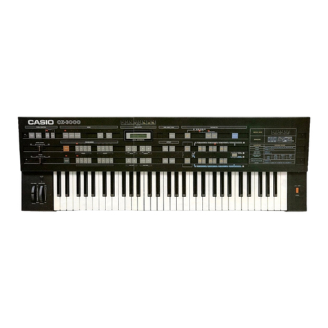
It was historically first used in 1984 in Casio synths of the CZ range. It is based on two
synced ramp oscillators. The synced (higher tuned) oscillator is scanning the sine wave
wavetable and is multiplied by the inverse of the lower tuned oscillator. Inpractical
terms this was supposed to emulate sweeps of a resonant filter on asawtooth
waveform. The implementation in Kastle is an adaptation of this method with wider
ranges on the oscillators and more formant vocally character. There is also the third
WAVESHAPE parameter which crossfades from secondary sinewave thru soft synced
sinewave all the way to the phase distortion.
TRACK & HOLD MODULATION (OSC OUT, MODE connected to “+”)
This is a not so common synthesis method. The main sinewave oscillator is going thru a
comparator which turns it into a variable pulse width waveform which is gating a track
& hold circuit.The second oscillator is being fed thru the track & hold which means that
when the pulse of the main oscillator is high the signal passes and when it becomes low
it holds static voltage. The threshold (WAVESHAPE) on the comparator sets the pulse
width and therefore the amount of the modulation while the PITCH and TIMBRE set the
frequencies of the oscillators.
FORMANT SYNTHESIS (SECONDARY OSC OUT, MODE connected to “+”)
This mode is inspired by the Helmholz Synthesizer (made in 1905) which was an
acoustic synthesizer based on several pitchforks tuned as several harmonic multiples of
a fundamental frequency that have been amplified by adjusting a mechanical shutter
of an acoustic resonator of corresponding frequency. Such a device could emulate
vowel sounds made up by sine waves of different harmonic frequencies mixed together.
Other Bastl Synthesizer manuals

