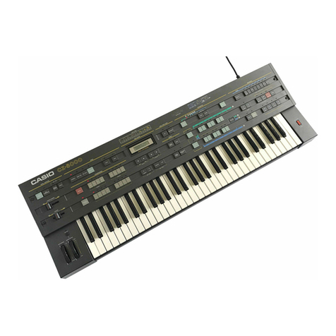
Casio Cosmosunthesizer CZ-3000 User manual

OPERATION MANUAL
MANUAL DE OPERACION

Thank you for purchasing the Casio CZ-3000. The CZ-3000 is atotally digital
synthesizer under LSI (large scale integrated circuit) control, and is designed
using the same principles that apply to analog synthesizers, thus eliminating the
frequently heard complaint about digital synthesizers that they are too complex.
This makes the unit actually ahybrid that combines the operational ease of an
analog synthesizer with the tonal quality of adigital model.
3Modes of the CZ-3000 ~\
1NORMAL MODE
•Play of preset timbres.
•Modification of timbre data recalled From memory.
•Creation of new sounds.
•Application of various effects to timbres,
•Saving of timbres created to built-in memory or optional RAM cartridge
RA-3.
2TONE MIX MODE
•Mixing of any two timbres.
•Independent setting of each timbre level.
3KEY SPLIT MODE
•Splitting of the keyboard into UPPER and LOWER portions for independent
play of two timbres.
•Independent setting of each timbre level and effect.

CONTENTS
GENERAL GUIDE
PERIPHERALS 8
|PART 1NORMAL MODE
PRESET VOICES „
MEMORY VOICES
EFFECTOVERALL CONTROL
PD (PHASE DISTORTIOM) SOCJND SOURCE.
8-STEP ENVELOPES
BLOCK CONFIGURATION
TIMBRE DATA WRITE/SAVE/LOAD
10
10
11
13
14
15
25
PART 2TONE MIX MOD
TONE MIX SETTING
EFFECTOVERALL CONTROL,., 28
28
PART 3KEY SPLIT MODE
KEY SPLIT SETTING
EFFECTOVERALL CONTROL 29
30
|PART 4MIDI
SEND/RECEIVE DATA ....
MIDI IN EACH MODE.....
31
32
CARE OF YOUR UNIT
SPECIFICATIONS
35
36

GENERAL GUIDE
d®<d> Power Switch
©OVERALL CONTROL SECTION [TOTAL CONTROL]
L
MASTER TUNE key
KEY TRANSPOSE key
i—Indicator
TOTAL CONTROL
I—ONUOFF—h
Ii"iC3 |
B|M STEKfO CWWU4 u.v
h
mil VOLUME uiK
GLIDE OM/GFF tey
^ORTAMKNTO ON/OFF key
Chorus Control
-Master Volume
•MASTER TONE key
CJsed to adjust the pitch of the entire key-
board within the range of ±100 cent (half
tone).
•KEY TRANSPOSE key
Transposes selections in half tone incre-
ments within the range of Qthrough Fft.
•PORTAMENTO ON/OFF key
Switches portamento ON and OFF. The in-
dicator above the key lights when ON, and
portamento is applied according to the por-
tamento time set using the PORTAMENTO
key in the bl U:-n. ':-<• >. i;, n, >.
•GLIDE ON/OFF key
Switches glide ON and OFF. The indicator
above the key lights when ON, and glide
ts applied according to the NOTE and
TIME values set using the GLIDE key in the
Effect Section •?).
•Master Volume
Adjusts the volume levels for the head-
phone and LINE OUT output,
•Chorus Control
Adjusts the chorus effect,
GENERAL GUIDE

MODE SELECT SECTION
The keys in this section are used to select one of the three modes.
®SOLO KEY
Switches between monophonic (ON) and polyphonic (OFF) play. An indicator will light
above the key when ON.
4MIDI KEY
Set to the ON position to specify the send/receive status when aMIDI instrument or per-
sonal computer is connected to the MIDI terminal on the back pane] of the keyboard.
©PROGRAMMER SECTION
Atotal of 64 timbres are contained in memory (32 PRESET and 32 MEMORY). The keys
in this section are used to select one of these timbres and to write timbres to memory.
PRESET BANK keys MEMORY BANK keys
Indicator
WRITE key
:—imC3 ^3 Indicator
HKAJ. I
COMPARE/RECALL key ±i-i ;m
-Voice Selectors-
•PRESET BANK keys
Used to select one of the lour preset banks.
An indicator will light above the key
pressed.
•MEMORY BANK keys
CJsed to select one of the four memory
banks. An indicator will light above the key
pressed.
•Voice Selectors
Used to select one of the eight timbre
memories in the selected bank. An indica-
tor will light above the key pressed, and a
message will appear on the LCD as shown
in the following illustration.
•WRITE key
Records timbres created using the
Parameter Section ;f$ in the MEMORY
BANK.
COMPARE/RECALL key
Compares atimbre created by modifying
avoice recalled from memory with the
original (unmodified) voice. The modified
timbre is temporarily stored in the COM-
PARE/RECALL area of memory and the
COMPARE/RECALL function is automati
cally turned ON (indicator lights above
key). The original voice is recalled when
OFF and the modified timbre is recalled
when ON.
*PRESET* C-2
SYNTH,, STRINGS
PRESET BANK C, tone number 2
MEMORY BANK A, lone number 4
GENERAL GUIDE

LIQUID CRYSTAL DISPLAY (LCD)
Such information as voice numbers, voice names, parameters and data appears on the
LLD as the keyboard js being used.
3DATA ENTRY SECTION
DATA ENTRY
-{
II'Jr FRI*
DIGITAL SYHTHEStflH
LCD
^Cursor
VALUE keys-
Lag u..d '«^» Ira
tlSJSUIM IEND
CURSOR keys
ENVELOPE STEP keys- rwvsrtT
•VALUE keys
Changes the data displayed on the LCD.
Pressing [)decreases the value by 1, while
pressing® increase the value by 1. Hold-
ing down either key will cause the value to
continuously increase/decrease. Also used
for SAVE and LOAD operations with aRAM
cartridge RA-3. (See page 26.)
•CURSOR key
Moves the cursor (bi inking mark below the
data) on the LCD. Basically, each press of
the Hkey moves the cursor one position
to the lefttwhile each press of the® key
moves the cursor one position to the right
when multiple data are being displayed.
*The®(YES) and ®<NO) cursor keys are
also used for SAVE and LOAD operations
using aRAM cartridge RA-3 (page 26),
fflj row ENVELOPE POINT keys
INITIALIZE of the timbre data (page 23).
•ENV STEP keys
Used to adjust the envelope steps of each
DCO, DCW and DCA envelopes provided
in the Parameter Section©. Each press of
ssof
in me Karameter Section0_a>. Each pre
the ®lowers the step while each pre
the Braises the step.
•ENVPOINY keys
Used to specify the SUSTAIN POINT and
END POINT of each DCO, DCW and DCA
envelope provided in the Parameter Sec-
tion©.,
®Cartridge key
The cartridge key is used in connection with an optional RAM cartridge RA-3 for saving
or loading timbre data of MEMORY BANK. Press as the initial step for performing SAVE
and LOAD operation between the keyboard and an optional RAM cartridge. (See page 26.)
GENERAL GUIDE
•5

_I
9EFFECT SECTION
The keys in this section are used to set data for applying four types of effects to all timbres
using the ON/OFF keys and PITCH BEND/MODULATION wheels. Any data modification
is performed using the Data Entry Section {£>.
PORTAMENTO key-
BEND RANGE key
EFFECT
iiii
POBT*
MINI" GLIDE
1
x=z
END
HIHI.il HDEVUrOM
t»»r»
GLIDE key
MODULATION DEPTH key
•PORTAMENTO key
Used to set the portamento time. Por-
tamento is applied according to the set
value when the PORTAMENTO ON/OFF
key of the Overall Control Section CO is ON.
•GLIDE key
Used to set the glide time. Glide is applied
according to the set value when the GLIDE
ON/OFF key of the Overall Control Sec-
tion is ON.
•BEND RANGE key
Used to set the PITCH BEND ©variation
range.
•MOD DEPTH key
Used to set the MODULATION variation
range. The MODULATION WHEEL©oper-
ates in the range of the set value when the
MODULATION ON/OFF key ©is ON.
PARAMETER SECTION
All parameters of timbre data are set using the keys in this section. All data modifications
(except for line select parameters) are performed using the Data Entry section 0.
®
PARAMETER
J] 12 1HHH-3J rzzs c
-I RIW3 HQtSE
H08€ -ib-uur
®- Iwwo
]3l
i
<Q>
WW1 I'IV 1HUQJhKt 1"I'CUdJ
11
[;_ -;
n.i
®
©WAVE FORM key
Press this key when you want to select the
basic wave form for Line 1.An indicator
lights above this key when ON.
(0)
h'DCO envelope key
This key lets you set the pitch envelope for
Line 1. An indicator lights above this key
when ON.
GENERAL GUIDE

©DCW KEY FOLLOW key
Press to make the wave form of the Line
1DCW approach apure sine wave accord-
ing to the pitch of the keys being played.
CdDDCW envelope key
Press to set the wave envelope for Line 1
.
An indicator lights above this key when
ON.
®DCA KEY FOLLOW key
Used to set the time variance between the
upper and lower registers of the keyboard
for DCA1.
ODDCA envelope key
Press to set the parameters of the Line 1
amplifier envelope. An indicator lights
above this key when ON,
®WAVE FORM key
Press to select the basic wave form for Line
2. An indicator lights above this key when
ON.
CftDCO envelope key
Sets the pitch envelope for Line 2. An in-
dicator lights above this key when ON.
C'DCW KEY FOLLOW key
Press to make the wave form of the Line
2DCW approach apure sine wave accord-
ing to the pitch of the keys being played.
IDCW envelope key
Press to set the wave envelope for Line 2.
An indicator lights above this key when
ON.
®DCA KEY FOLLOW key
Used to set the time variance between the
upper and lower registers of the keyboard
for DCA 2.
(ODCA envelope key
Press to set the parameters of the Line 2
amplifier envelope. An indicator lights
above this key when ON.
©VIBRATO key
Press to set the vibrato effect independent-
ly for each tone. Data setting itself is per-
formed in the Data Entry section.
©OCTAVE keys
Press to shift the pitch range of each tone
up or down in one octave steps. Data set-
ting itself Is performed in the Data Entry
section.
©DETUNE key
Press to detune the pitch of Line 1or Line
2without changing the tone, for Line 1'or
Line 2\
©LINE SELECT key
Changes line select in the order UJ -* 20
-* \S\ +3D -> ED \ffl .The indicator
above the selected line combination lights
up.
©RING key
Causes Line 1'or Line 2' to be ring modu-
lated by Line 1. An indicator lights above
this key when ON.
©NOISE key
Causes Line 1
'or Line 2' to be modulated
by noise. An indicator lights above this key
when ON.
©INITIALIZE key
Initializes the settings of the various
parameters (sets the respective data to 0),
thus making it easier to start creating
sounds right from the beginning. Press the
INITIALIZE key and simultaneously press
the key of the parameter to be initialized.
'GENERAL GUIDE
©MODULATION ON/OFF KEY
MODULATION WHEEL
Turned to adjust the vibrato depth according to the variation range set using the MOD
DEPTH key in the Effect Section®,
PITCH BEND WHEEL
Turned to controi the pitch according to the variation set using the BEND RANGE key
in the Effect Section®.
KEYBOARD
PERIPHERALS
The CZ-3000 is not equipped with built-in speakers. Akeyboard amp is required except
when using headphones.
•Connection Diagram
CD' Power termina
®FOOT VOLUME terminal ©LIME OUT terminal (R/L)
6) SUSTAIN terminal
Accessory power cord
(3.) PHONES terminal
Sustain pedal Foot volume control
Keyboard amp
{AS-3000, AS-2000, etc) Headphones
PF.RIPHKRALS
a
•H*

(D POWER TERMINAL
For connection of accessory power cord.
(DUNE OUT TERMINAL (RIGHT/LEFT)
For connection of aspeaker with abuilt-in keyboard amp (such as the optional AS-3000).
•Stereo output is only possible when both the RIGHT and LEFT terminals are connect-
ed to speakers.
Connecting only one of the two terminals will result in monaural output.
•->
3PHONES TERMINAL
-..a,
For connection of headphones.
4MIDI TERMINALS
For connection of another keyboard or acomputer equipped with MIDI terminals.
CD FOOT VOLUME TERMINAL
For connection of afoot volume pedal (optional VP-2) which allows fine adjustments
of volume during keyboard play.
*No sound is heard when the foot volume pedal is not pressed or when the main volume
of the keyboard is set to MIN.
fS\
6SUSTAIN TERMINAL
For connection of asustain pedal (optional SP-1). Sustain effect applied when pedal
is pressed.
®PROTECT SWITCH
Used to protect against erasure of timbre data from the Programmer section or data
played using the Sequencer Section,
MEMORY PROTECT FUNCTION
WRITE is impossible and data LOAD from an optional RAM
cartridge is impossible when the PROTECT switch is in the
ON position. This protects against inadvertently erasing data
(see page 25). The switch should usually be kept OM and only
be set to OFF for WRITE and LOAD operations.
PROTECT
OFF ON
Usually left OM
CARTRIDGE SLOT
For loading aseparately available RAM cartridge (RAO). (See page 26.)
rOPTIONS (SEPARATELY AVAILABLE)
•Keyboard amp (AS-300G)
•Keyboard amp (AS-2000)
•Keyboard amp (AS-20)
•Volume Foot control (VP-2)
•Sustain pedal (SP-1)
•Headphones (CP-2)
*AII options should be available from dealers that handle the CZ series.
•RAM cartridge (RA-3)
•Stand (CS-2)
•Stand (CS-5)
•Protective case (HOI 6)
•Flight case(HC-lOO)
J
PERIPHERALS

PART 1*NORMAL MOD i
PRESET VOICES
•First, turn power ON by pressing the power switch located to the right of the keyboard.
The display will appear as shown here when power is switched OH.
^OU !«l
Kiwi K;#
PRESET* H-l
BRASS ENS.l
,-tDisplay when power is switched ON.
At this time the keyboard is set to the NORMAL mode and the Programmer Section auto-
matically recalls PRESET A-1, BRASS ENSEMBLE.
32 preset voices selected using the PRESET BANK keys and VOICE selectors can be used
for keyboard play.
.i..
PRESET BANK keys
VOICE selectors
XPRESET BANK selection
,,ijjjia±]_
(2) VOICE selection
'The name of the preset voice selected will be shown on the LCD.
PRESET VOICE TABLE
No. \^ ABC D
1BRASS ENSEMBLE 1SYNTH. BRASS BRASS ENSEMBLE 2TRUMPET
2STRING ENSEMBLE 1STRING ENSEMBLE 2SYNTH, STRINGS VIOLIN*
3JAZZ ORGAN ELEC. PIANO ACCORDION FANTASTIC ORGAN
4WHISTLE* FLUTE #BLUES HARMONICA DOUBLE REEO
5FAT BASS SYNTH. BASS ELEC. GUITAR METALLIC SOUND
6VIBRAPHONE CRISPY XYLOPHONE SYNTH. GLOCKENSPIEL CARIMBA
7SYNTH. DRUMS STEEL DRUM SYNTH. PERCUSSION CONGA
8HUMAN VOICE FAIRY TALE CARILLON TYPHOON SOUND
*16-tone polyphonic (1 DCO). Unmarked are 8-tone polyphonic (2 DCO).
MEMORY VOICES
The memory bank is composed of 32 memory areas to which original timbre data creat-
ed using the Parameter Section can be written. MEMORY BANK keys Athrough Dand
VOICE selectors 1through 8of the Programmer Section are used to select amemory
voice for recall.
PRESET VOICES/MEMORY VOICES
ID

v.;.
MEMORY BANK keys (A- D)—> *
(T) MEMORY BAMK selection
VOICE selectors (1-8)—>< -2LjM 1sj.IT"
:
&• VOICE selection
•The memory bank and voice number are displayed on the LCD,
•The 32 memories of the MEMORY BAMK are set at the factory with sample tones includ-
ed in the separate "DATA BOOK".
EFFECT/OVERALL CONTROL
—
—
j
Portamento time The following appears on the LCD when the PORTAMENTO key in the Effect Section is ON:
EFFECT
PG*TA-
wrh-rn •1:1 PORTAMENTO
TIME=25
(00 ^TIME 599)
The VALUE Qand Ekeys in the Data Entry Section are used to set the portamento time
within arange of 00 through 99. The portamento time increases (portamento becomes
slower) as the numeric value increases.
PORTAMENTO ON/OFF
Portamento is switched ON and OFF using the PORTAMENTO ON/OFF key in the Over-
all Control Section.
*Portamento is only applied for legato (subsequent keys are pressed while previously
pressed keys are held down) when portamento is switched ON while the SOLO key is ON.
Portamento and glide mutually cancel each other. p^™^
-GLIDE NOTE/TIME
The following appears on the LCD when
the GLIDE key in the Effect Section is ON:
Cursor -24 gNOTE£+24
00 <TIME ^99
NOTE indicates the pitch divergence from standard of the key pressed. Settings are made
in half-tone units in the range of 2octaves up and down (±24 half tones). When the key-
board is pressed, the pitch successively changes from the set pitch to standard, thus
producing aglide effect. The difference in pitch becomes greater as the numeric value
increases,
TIME Indicates the glide time and is set within the range of 00 through 99. Glide time
becomes longer (glide becomes slower) as the numeric value increases.
The cursor is moved to TIME using the cursor keys in the Entry Section and the numeric
value is set using the VALUE keys.
IPART 1NORMAL MODE
11

•GLIDE ON/OFF Glide is switched ON and OFF using the GLIDE ON/OFF key in the Overall Control Section.
*Portamento and glide mutually cancel each other.
•PITCH BEND Pitch is controlled by turning the PITCH BEND WHEEL
located to the left of the keyboard.
FITCH tUMO
Pitch increases
Pitch decreases
ii :h-'.
•BEND RANGE The following appears on the LCD when
the BEND RANGE key in the Effect Sec-
tion is ON: {00 sRANGES 12)
The VALUE keys in the Data Entry Section are used to set the pitch bend width at half-
tone intervals within the range of 00 through 12 (±1octave). Each increment of the nu-
meric value increases the bend width by ±100 cent (±half tone).
MODULATION DEPTH
The following appears on the LCD when
the MODULATION DEPTH key in the
Effect Section is ON:
MODULATION
DEPTH=25
(00 sDEPTHS99)
The VAUCJE keys in the Data Entry Section are used to set the MODULATION WHEEL depth
within a range of 00 through 99,
MODULATION WHEEL
When the ON/OFF key above the MODULATION WHEEL is ON,
rotating the wheel away from the front of the unit (see illustra-
tion) will gradually increase the depth of vibrato. The MODU-
LATION DEPTH set in the Effect Section will be applied with
the wheel is rotated to its full (MAX) extent
Btt/orr
MOGULAWOH
MM
•MASTER TONE -tt-
The following appears on the LCD when
the MASTER TUNE key is ON: MASTER TUNE
PUSH UfiLUE KEY
Each press of the 0or0VALUE key will respectively lower or raise pitch by 1.7 cent.
•Simultaneously pressing the Qand (*] keys will return pitch to the standard value
(A4 =442Hz).
•The pitch value can be successively changed at high speed by holding down either VALUE
key.
KEY TRANSPOSE
The following appears on the LCD when
the KEY TRANSPOSE key is ON:
-»
12
EFFECT/OVERALL C(

Each press of the ©or ®VALUE key will respectively lower or raise the key by half
tone steps. The key is displayed at the cursor position.
tnitial value.
G^-A^-A*-Bb+-B*-C-*Cl-*D-^El-+E-> F— F
SOLO
SOLO key ON
Volume SOLO key OFF
Volume
KEY ON KEY ON
<Z)
KEY ON©simultaneously deletes note©.
KCV ON
CD KEY ON
Note© remains even at KEY ON®.
(Illustration shows anon-sustained tone.)
PD (PHASE DISTORTION) SOUND SOURCE
The CZ-3000 employs aunique, CASIO developed PD (Phase Distortion) sound source
system. This system is capable of producing avariety of wave forms by distorting the read
phase angles of sine and cosine waves that are Written in ROM, The pattern ol the read
phase angle distortion is determined by the specification of the DCO (VCO of analog syn-
thesizer) WAVE FORM. The magnitude (modulation depth) of the read angle distortion
corresponds to the momentary value of the DCW (VCF of analog synthesizer) envelope.
(Fig. 1)
Phase angle
Waveform
Polarity (+/-) cos? reversed for sake of
Fig, 1illustrates output of anon-
distorted cosine wave when aco-
sine wave in ROM is read with a
linear phase angle. The phase
angle is read at acofisLmil speed
from through 2ir.
What would happen if we in-
crease the phase angle read
speed from through t and
decrease it from ir through 2t?
<Fig. 2)
As shown in Fig. 2, the phase
angle read is distorted rather
than linear, and the output co-
sine wave takes on what is close
to asaw-tooth pattern.
What would happen now if we
further increase the phase angle
read speed from through tt
and decrease it from xthrough
2t?
<Fig. 3)
Fig. 3 shows that the output co-
sine wave is almost aperfect
saw-tooth pattern.
PART 1NORMAL MODE
13

The revolutionary PD sound source system thus makes it possible to output waveforms
that differ from cosine waves by simply distorting the cosine (or sine) wave read from ROM,
Figs. "I through 3illustrate the patterns produced by increasing the phase angle read speed
from through it while decreasing the speed from it through 2x. This is the pattern effect-
ed when the SAWTOOTH waveform is selected in the DCO parameter.
Read phase angles are also distorted in accordance with the selection of the other DCO
parameter WAVE FORMs, thus making avariety of waveform outputs possible.
The magnitude of the read phase angle distortion corresponds to the momentary value
(change over time) of the DCW envelope. When the DCW envelope is set as shown in Fig.
4, an undistorted cosine wave is output at point (a), distortion reaches its peak at point
©, and asawtooth pattern as shown in Fig. 3is output. Distortion is reduced (modulation
become shallower) at point®, and apattern that is somewhere between acosine wave
and asaw-tooth wave as illustrated in Fig. 2is output.
When WAVE FORM is set to saw-tooth.
DCW envelope
tey ON Key OFF
POINTS TO REMEMBER
1)The pattern of the read phase angle distortion corresponds to the WAVE FORM
setting of the DCO parameter.
2)The magnitude of the read output phase angle distortion (modulation depth) cor-
responds to the momentary value of the DCW envelope.
8-STEP ENVELOPES
The CZ-3000 features adual system DCO/DCW/DCA, and each system has its own indepen-
dent envelope generator for control of changes in notes, timbres and volume over time.
The envelope generators can set up to eight steps including setting of the sustain point
(the level at which anote is sustained while akey is depressed). This provides greater ver-
satility than the conventional ADSR generator and makes sound creation possibilities vir*
tually unlimited.
(Fig. 1)
K«y QN -...,' '-!l I
r
lV^**£l^\li
1
*Ri through Rb indicate
the RATE (slope) of
each various steps,
while Li through L* in*
dicate the LEVEL (des-
tination level). Lj is
reached at aslope of
Rj in STEP lpL2is
reached at aslope of
R2in STEP 2, etc.
C14
8-STEP ENVELOPES i

Fig. 1shows an example of an envelope employing 8steps. There are two attacks before
the sustain point, as well as athird attack after the key is released, resulting in an "after-
envelope".
(Fig. 2) (Fig. 3)
Li CZ-3000 Conventional anal og synthesizers
Key ON
1Attack •
time
Analog synthesizers usually require the setting of envelopes according to 4parameters:
Attack time, Decay time, Sustain level and Release time (hence, the name ADSR system).
With the envelope generator of the CZ-3000, only 3step settings are required to attain
the same effect.
BLOCK CONFIGURATION
The PD sound source of the CZ-3000 makes it afully digital synthesizer. Actually, however,
the DCO (pitch and basic waveform setting), DCW (timbre control), and DCA (volume con-
trol) digital circuits of the Parameter Section result in ablock configuration that closely
resembles an analog synthesizer. The block configuration of the CZ-3000 consists of LIME
1and LIME 2which make up adual system. DETUNE allows you to create differences
between the sounds generated by LINE 1and 2to produce subtle nuances. With LIME
SELECT, asingle line can be output or combined with the detuned line for atotal of 4
line output settings.
CZ-3000 block configuration
.r-.r iDCW I
(Timbre)
*
ENV
DCA I
(Volume)
_JNV 1[^ ir-
,^D£TUNt -J SELECT
LIN! 2DCW 2^DCA 2I
(Timbre) ^^ (Volume)
DCW 2
(Timbre)'
•VIBRATO is the parameter that oscillates the low frequencies of the DCO and applies avibrato
effect Another parameter applied to DCO is OCTAVE.
DCO (DIGITAL CONTROLLED OSCILLATOR)
DCO corresponds to the VCO of an analog synthesizer, and is comprised of WAVE FORM
for selection of the basic waveform and ENV (pitch envelope) for control of the pitch over
time for apressed key. The dual system line provides an independent DCO 1and DCO
2which can be used as desired.
PART 1NORMAL MODE
15

•WAVE FORM Determines the basic waveform of a timbre. Independent settings can be made using the
DCO 1and DCO 2keys.
As can be seen in fig. a, there are eight types of basic waveforms: from SAWTOOTH
to RESONANCE 111. Any one of these eight waveforms can be combined as shown in fig,
bto produce atotal of 33 waveforms suitable for virtually any application.
(fig- a) l\ «n_ '-A_ '-A/\ <f,9b) KTL
SAW-TOOTH iUJAl* -ii. sr |-;uiHI .Ni
:.. /1_ f
--llhu. 'JUL !!.
SW-^UlSE RESCViMVCG IRESONANCE tt RE&QftANCC I
(SAW-TOOTH) {TRIANGLE) (TRAPEZOID!-
AJk*.
•The three RESONANCE waveforms cannot be used in combination with each other.
When the WAVEFORM key is ON, the LCD appears as shown in Fig. 1
.
(F*g- 1) indicator lights.
vL WFIUE FORM
FIRSTS SECQHD=B|
-Cursor
Fig, 1indicates that only the saw-tooth pattern is selected. (Only the FIRST waveform is
applied when SECOND =is displayed) At this time, the VALUE keys can be used to
set FIRST (the current position of the cursor) to avalue from 1through 8to select the
required waveform. Then the CURSOR keys can be used to move the cursor under the value
of SECOND and the another waveform can be set using the VALUE keys (see Fig. 2).
This procedure is used to select one of the 33 combinations of basic waveforms.
(Fig. 2)
:,Y; Either of the CURSOR keys is used to
move the cursor. WflUE FORM
FIRST* 1SECOND=0
(|)The VALUE keys are used to change the
numeric value.
*Giving the same value to FIRST and SECOND is the same as when SECOND =0,
*FIRST =1, SECOND =2produces the same effect as FIRST =2, SECOND =1.
•DCO ENVELOPE (PITCH ENVELOPE)
DCO controls changes in pitch over time. Independent envelopes can be set using the DCO
1and DCO 2ENV keys.
The PITCH envelope sets the change in pitch over time up to 8levels for pressed keys
in accordance with the RATE and LEVEL.
Now let's set up an actual 4-step envelope as shown in Fig. 3.
(Fig. 3)
Pitch
99
au
.This pitch maintained
/while key is pressed.
Ri
Li SUSTAIN
RUN I
ON
Time
KEY
OFF POINT
sil R1 STEP 2STEP 3SHT'4
FWCTE 0:J 72 60 20
LEVEL 99 66 r-M on
sua END #** SUS .** END
16
——«=—
-
BLOCK CONFIGURATION

CO When the ENV key of the DCO 1or DCO 2is pressed, the following appears on the LCD.
StiS will be displayed if the displayed STEP is asustain point.
END will be displayed if it is an end point.
Pitch envelope STEP 1selected.
PITCH STEP! +++
RfiTE=".«< LEUEL=".« /00gmimj^99 ''
VOOsnim £99 1
Rale of step 1
Destination level of step 1,
<D Use the ®VALUE key to raise the RATE
value to 99.
CD Use either one of the CURSOR keys to
move the cursor under the LEVEL value.
Use the HVALUE key to raise the
LEVEL value to 99, This completes the
setting of STEP 1.
©Use the ENV STEP Skey to advance
to STEP 2. After ensuring the STEP 2
is displayed, follow the same procedures
outlined for STEP 1to set the RATE to
72 and the LEVEL to 66.
®Press the ENV POINT SUSTAIN key to
designate STEP 2as aSUSTAIN POINT.
(D Use the ENV STEP ®key to advance
to STEP 3and set the RATE to 60 and
the LEVEL to 24.
(J) Use the ENV STEP Bkey to advance
to STEP 4and set the RATE to 20. Then
press the ENV POINT END key to set
the END POINT, and the LEVEL will au-
tomatically be set to 00.
*lt is not necessary to press the END key
PITCH STEPi ***
RFlTE-99 LEUELj—
PITCH STEPI ***
RflTE=99 LEUEL=99
PITCH STEP2 ***
RflTE=72 LEUEL=66
SUSTAIN POINT
*Mi Ml 'll
PITCH STEP2
RflTE=72 LEUEL=66
PITCH STEP3 ***
RflTE=60 LEUEL=23
END POINT
PITCH STEP4 END
RflTE=20 LEUEL=@@
LEVEL of the last step is 00.
if the END POINT is already set.
RATE/LEVEL NUMERIC VALUES
RATE
The RATE indicates the slope (interior angle in relation
to horizontal) of each step in the envelope. R-99 indi-
cates nearly 90° while R=indicates nearly 0°. Since
the value used is an absolute value, the slope increases
and decreases in direct proportion with the value of R,
regardless of whether the pattern shows arise or fall.
This means that asteep incline results In aquick level
change while agentle incline results in aslow level
change.
LEVEL
The LEVEL indicates up to what point each step rises
or falls (destination level), and the range is from 00
through 99, For the DCO envelope, LEVEL means the
pilch height, cind avalue of 00 is (hi: pilch of •: pressed
key. For the DCW envelope, L=99 results in abasic
waveform {see page 20 for details). For the DCA enve-
lope, LEVEL means the volume.
LEVEL
Pr* =99 AjWee
P: =6& 7IML
fl fi ^99
PART 1NORMAL MODE
17'

MOTES
•Even if the ENV STEP© key is pressed, it will be impossible to advance from the
present step if END POINT is specified. In this case, press the ENV POINT END
key again to cancel the END point and then press the ENV STEPS key. If an END
point is cancelled within STEP 1through 7, an END POINT is automatically desig-
nated in STEP 8and previously set data is automatically restored.
•The LEVEL for aSTEP that includes an END POINT is fixed as 00 and cannot be
changed.
•When aSUSTAIN POINT is designated in aSTEP. SUSTAIN POlNTs set in other
STEPs are cancelled.
iDCW (DIGITAL CONTROLLED WAVE)
DCW corresponds to the VCF of an analog synthesizer, and is comprised of KEY FOL-
LOW for control of the waveform corresponding to the keyboard range, and ENV (wave
envelope). The dual system line provides an independent DCO 1and DCO 2which can
be used as desired.
KEY FOLLOW/DCW
This parameter applies adifference change in the DCW envelope level in accordance with
the pitch of the key played, The DCW 1and DCW 2KEY FOLLOW keys are used to in-
dependently set each key follow.
Key follow can be set to levels ranging from through 9. The higher the note played,
the closer, the waveform comes to being asine (cosine) wave. (See Fig. 4.)
(Fig. 4)
Sine wave
The LCD appears as in Fig. 5when the DCW KEY FOLLOW key is pressed.
(Fig. 5)
-MC— KEY FOLLOW
UE RANGE*!! (0s^9)
The VALUE keys in the Data Entry Section are used to set the RANGE value within a
range of through 9. The greater the RANGE value the greater the waveform level vari-
ance (timbre change rate) in the upper registers. Asetting of 9represents the maximum
variance.
BLOCK CONFIGURATION
18

DCW (WAVE) ENVELOPE
This parameter controls the timbre (waveform) change over time, and the DCW 1and
DCW 2EMV keys are used to independently set the timbre envelopes. The timbre enve-
lope is used to set the timbre (waveform) change over time for apressed key in accor-
dance with the RATE (slope) and LEVEL (destination level). Settings can be made to a
maximum of 8steps,
(Fig, 6) WAVE FORM 1(Saw-tooth)
LEVEL
Basic
waveform ,_L;
A"'
I\
ii, *
This timbre (wave-
/form) sustained while
key Is depressed.
Sim:
L* =SUSTAIN
PO*IT
,P«
CO •:.£V
ON KEY P^ Timhj
STEP1 STEP 2STEP 3
MAin 75 60 60
LEVEL 99 SO cc
SUS, END *** sus END
OFF END
POINT
The change of timbre over time is in accordance with the DCW envelope LEVEL. Asine
wave is attained when L=00 and the basic waveform is attained when L=99.
The LCD appears as in Fig, 7when the DCW 1or DCW 2ENV key is ON.
(Fig. 7) Wave envelope STEP 1is selected. SGS will be displayed here if the dis-
played STEP is asustain point. END
will be displayed if it is an end point
WfiUE STEP! ***
RHTE
=
m'm-- LEUEL=«•n*
Rate of STEP 1, Destination level of STEP 1.
'Operational procedures are identical to those previously explained for the DCO enve-
lope (page 17). Data is set using the VALUE, CURSOR, ENV STEP and EMV POINT SGS
TAIN/END keys.
DCA (DIGITAL CONTROLLED AMPLIFIER)
DCA corresponds to the VCA of an analog synthesizer and independent volume enve-
lopes can be set using the DCA 1and DCA 2EMV keys,
KEY FOLLOW/DCA
This is the parameter that applies avariance to the DCA envelope 3n accordance with
the pitch of the key played. The DCW 1and DCW 2KEY FOLLOW keys are used to In-
dependently set each key follow.
The higher the note played, the shorter the time of the volume envelope,
(Fig. 8)
|..'V-|.:
I, Volume envelope (DCA)
Time becomes shorter.
PART 1NORMAL MODE
19
Other manuals for Cosmosunthesizer CZ-3000
1
Table of contents
Other Casio Synthesizer manuals

Casio
Casio VZ-1 User manual

Casio
Casio Casiotone CT-360 User manual

Casio
Casio CTK-601 User manual

Casio
Casio CDP-S105 User manual

Casio
Casio CTK-711EX User manual

Casio
Casio Privia PX-S1000 User manual

Casio
Casio FZ-1 User manual

Casio
Casio XW-P1 User manual

Casio
Casio Celviano AP-40 User manual

Casio
Casio CTK-495 User manual

Casio
Casio CTK-50 User manual

Casio
Casio Casiotone CT-S200 User manual

Casio
Casio ToneBank CT-420 User manual

Casio
Casio CTK-495 User manual

Casio
Casio CTK-4400 User manual

Casio
Casio CTK-810 User manual

Casio
Casio SK-100 User manual

Casio
Casio CZ Series User manual

Casio
Casio ToneBank CT-420 User manual

Casio
Casio MA-150 User manual