Bath Authority DreamLine Neptune User manual

NEPTUNE Steam Room Installation Instructions
IMPORTANT
Please read carefully the following instructions before installing your shower cabin. If you
have any questions on this shower cabin installation - please call our technical support
specialists Monday to Friday 9:00AM – 5:00PM EST at 1-866-731-8378 Option 3 or e-mail
our technical support group at support@BathAuthority.com
Our product may have changes without prior notice

IMPORTANT SAFETY
INFORMATION
Your STEAM SHOWER is equipped with
an Auto-Drain feature. 1-3 minutes after
the unit control panel power is turned off
any remaining hot water in the steam
generator system is automatically drained
into the shower cabin.
For your safety – please do not turn off the
power button on the control unit until you
are ready to exit the cabin.
If you have any question on this feature –
please call our Technical Support Center at
1-866-731-8378, Option 3
Rev. 1. 3. 2

WARNING
Please, make sure you do the following:
9Electrical grounding is required on the steam generator;
9All electrical supplies must be disconnected when servicing the
steam generator;
9All wiring must be installed by a licensed electrician (please
consult your local codes);
9All plumbing must be installed by a licensed plumber (please,
consult your local codes);
9Never shut off water while steam generator is in use;
9Never touch the wiring while the unit is in use to avoid electric
shock due to high voltage that runs in the equipment.
Follow these steps to avoid the risk of overheating or scalding:
9Exit the shower cabin immediately if you feel uncomfortable, dizzy
or sleepy. By staying too long in a heated area you increase the
risk of overheating;
9Do not touch the steam head. Keep 12” distance from the steam
outlet when generator is in use;
9Make sure children are under supervision at all times;
9Consult your doctor before using the steam shower cabin if you
are pregnant, diabetic, in poor health or under medical care;
9Do not use alcohol, drugs or medication in conjunction with taking
a steam shower as this may cause unconsciousness.
Rev. 1. 3. 3

Preparation
1. After opening all the boxes, read this introduction carefully, check all the packed parts
are complete by cross checking all the components against the “Detailed Diagram of
Shower Cabin Components”. Examine for shipping damage. If the unit has been
damaged or has a finishing defect, please contact your local distributor within 3
business days. Please note that Bath Authority™ / DreamLine™ will not replace any
damaged product or parts free of charge after 3 business days or if the product
has been installed. Contact your distributor or distributor if you have any questions.
2. Please note that you should consult your local building codes on questions on
installation compliance standards. Building and plumbing codes vary by location,
and DreamLine is not responsible for code compliance standards for your
project.
3. Install all of the required plumbing and drainage before securing the shower. Use a
competent and licensed (if required by local code) plumber for all plumbing
installation and licensed electrician for all electric installation.
4. Please insure that prior to the installation the floor is leveled and solid and will be able to
support the total weight of the unit and its occupant. Also make sure the walls are at
right angles. While some adjustment in leveling of the tray is possible, irregular floor
level or improper angle of side walls will result in serious problems for your installation.
Please, note that there are some adjustments and drilling might be necessary during the
installation process.
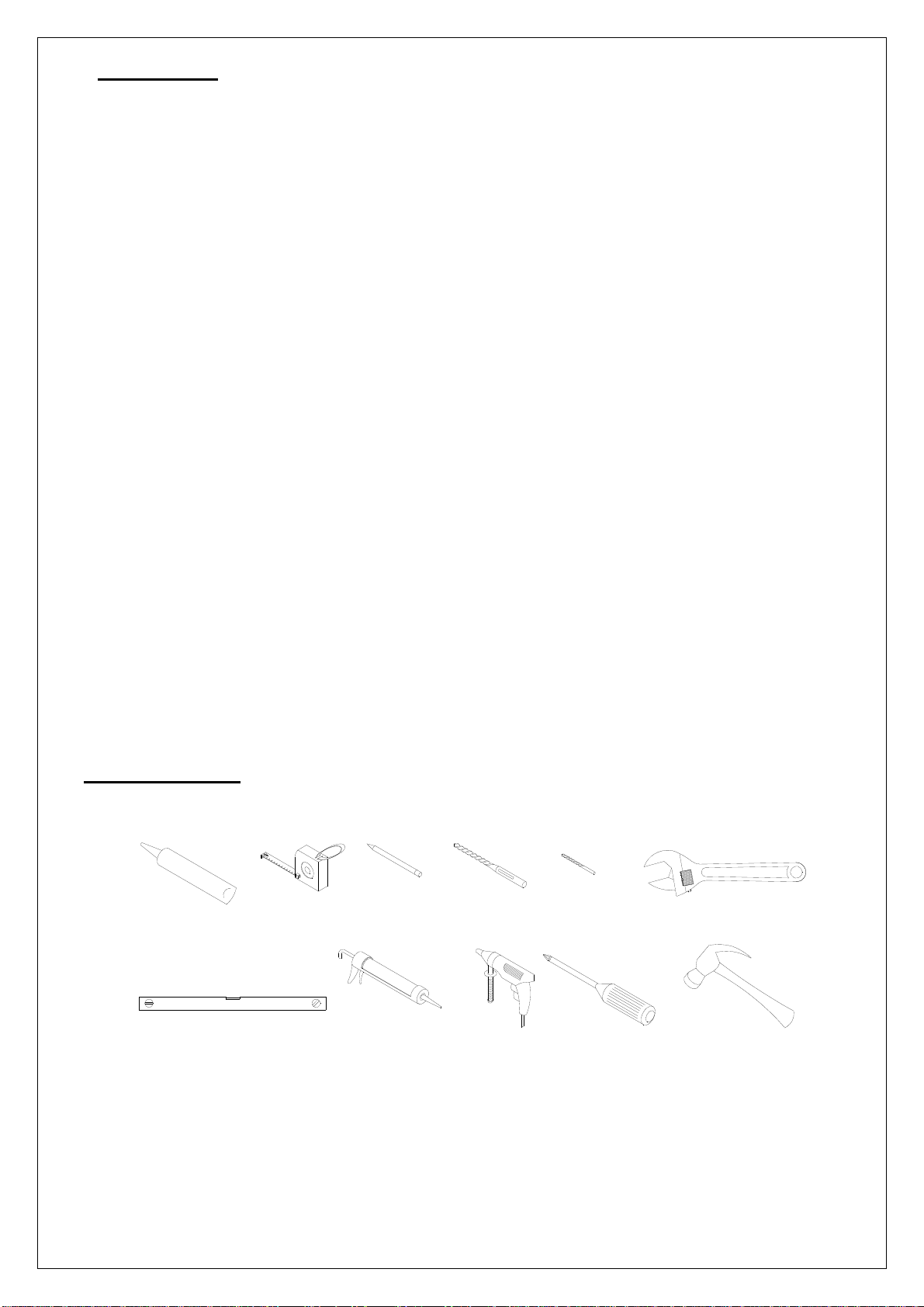
Tools Required
Caulk Tape
Measure
Level
Pencil Drill bit
(D=6mm) Drill bit
(D=3mm)
Caulk
Gun Electric
Drill Phillips
Screwdriver Hammer
Wrench
Rev. 1. 3. 4

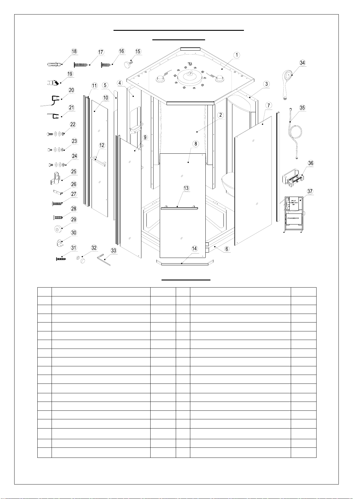
Detailed Diagram of Steam Room
Components
Packing List
01 Roof 1pc 20 Anti-water strip 1pcs
02 Back panel 1pc 21 Bottom anti-water strip 2pcs
03 Side panel 1pc 22 Bolt M6×40 (with nut, washer) 12pcs
04 Shelf panel 1pc 23 Bolt M6×20 (with nut, washer) 39pcs
05 Control panel 1pc 24 Bolt M6×16 (with nut, washer) 9pcs
06 Bottom tray 1pc 25 Pivot assembly 2pcs
07 Wide stationary glass 1pc 26 Gasket 4pcs
08 Glass door 1pc 27 Round head bolt M8×14 4pcs
09 Narrow stationary glass 1pc 28 Flat head bolt M8×20 4pcs
10 Maintenance door 1pc 29 Washer 4pcs
11 Wall profile 1pc 30 Glass bracket 4pcs
12 Handle for maintenance door 1pc 31 Round head screw ST4.2×25 4pcs
13 Glass door handle 1pc 32 Decorative cover 4sets
14 Pivot bar 2pcs 33 Hex wrench (different size) 2pcs
15 Bolt 2pcs 34 Hand shower 1pc
16 Round head screw ST4.2×12 10pcs 35 Hand shower hose 1pc
17 Round head screw ST4.2×25 13pcs 36 Foot massager 1pc
18 Wall anchor 3pcs 37 Generator assembly 1pc
19 Magnetic strip 2pcs
After you have checked that all components are there, you will be ready to start the
installation of your DreamLineTM steam room.
Rev. 1. 3. 5

Cabin Installation
1. Choose the location where you cabin will be installed. Mark the location of the tray.
Install the drain pipe according to drawing Fig 1. Be sure the upper edge of the 2” elbow
or bushing will be on the level or below the floor level Fig 2.
2. Prep the floor where the cabin will be installed. Floor must to be leveled, strong enough
and solid and will be able to support the total weight of the unit and its occupant.
3. Install the drain to the tray according the drain installation manual (supplied by drain
manufactory) Fig 3.
4. Move the Tray (06) to the required position. Check the level of the tray, alignment of the
drain pipe and the drain (Fig 4). If drain pipe need to be adjusted do it now. If tray in not
leveled, move tray out and re-level floor. Place tray back and check it again.
5. Install the water outlet and power supply box. You need 1/2” minimum water supply
lines for hot and cold water with shout off valves. Power supply is required 20A 220v
dedicated #12/3 romex wire line with GFCI breaker. Please check your local codes
before wiring as your local requirements may be different. (Note: Figure 4 shows
water and power location for the control panel to be installed on the left side of the tray.)
Your unit is reversible for right or left hand installation. If the control panel is
planned to be on the right side of the tray, the location of the water outlet and power
supply box should also be moved to the right side of wall. See Fig 4 for details.
6. Move the Tray (06) to the assemble area. Be advised assemble area must to be as
close to the installation area as possible to make the movement of the assembled cabin
easy. Apply silicone sealant along the holes on the tray. Connect the Back panel (02)
and the tray with Bolt M6×40 (22). See Fig 5 and Fig 6 for details.
NOTE: For steps 6, 7 and 8, it will be necessary to apply silicone sealant between
the panels and the panels and tray.
7. Connect the Back panel (02) and the Side panel (03) with Bolt M6×20 (with nut,
washer) (23). Secure the side panel to the tray with Bolt M6×40 (22). (In these
instructions the panel is shown on the right side of the tray, but for reverse installation -
the side panel can also be installed on the left of the tray). See Fig 7 for details.
8. Connect the Shelf panel (04) and the Back panel (02) with Bolt M6×20 (with nut,
washer) (23). Secure the shelf panel to the tray with Bolt M6×40 (22). See Fig 8 for
details.
9. Secure the shelf panel and the Control panel (05) with M6×20 bolts; then secure the
control panel to the tray with Round head screw ST4.2×25 screws (17). See Fig 9 for
details.
Install the Wide stationary glass (07) to the side panel with Bolt M6×16 (24). Apply
silicone sealant between the side panel and the aluminum profile. See Fig 10 and Fig 11
for details.
10.Secure the Narrow stationary glass (09) to the control panel with Round head screw
ST4.2×12 (16). Apply silicone sealant between the control panel and the aluminum
profile. See Fig 12 and Fig 13 for details.
11.Locate the Pivot bars (14), Pivot assembly (25) and parts 26, 27, 28, 29, 30, 33.
Confirm the direction of the opening of the door. For left hinge installation 3 holes on
the pivot bars should be on the left; for right hinge installation 3 holes on the pivot bars
should be on the right side. Connect the stationary glass panels with pivot bars using
the Glass bracket (30), Flat head bolt M8×20 (28) and Washer (29). Do not forget
to place the clear rubber Gasket (26) between the pivot bars and the glass to
prevent contact of the glass to the metal. See Fig 14/1, 14/2 for details.
12.Fasten Pivot assemblies (25) to the pivot bar using Round head bolt M8×14 (27).
See Fig 14/3 for details.
Rev. 1. 3. 6

13.Secure the Generator assembly (37) to the back corner of the tray with Round head
screw ST4.2×25 (17). See Fig 15 for details.
14.Apply silicone sealant on the top of the acrylic panels. Secure the roof to the back panel,
side panel, shelf panel and the control panel with Round head screw ST4.2×25 (17)
and Bolt M6×20 (23). See Fig 16 for details.
15.Connect the shower head connector and its hose. Pool all wires from roof electric
components (Depending on your model and futures) down to the steam generator
compartment. Fig 17.
16. Move the shower cabin assembly to the required position. Fig 18.
17.Measure the distance from straight part of the elbow or bushing to the top of the drain
less 1/2”. See Fig 19/1 and Fig 19/2. Cut peace of the 2” PVC pipe according the
measurements. See Fig 19/2 and Fig 19/3. Clean PVC pipe and elbow according the
PVC glue manufactory instructions. Apply the PVC glue to the elbow and PVC pipe and
push pipe down into elbow. Hold it for 45 sec to 1 min to glue it together. Fig 19/4, 19/5,
19/6.
18.After the glue had been dried finish the assembling of the drain according with drain
manufactory instruction. Fig 19/7, 19/8, Fig 20.
19.Locate the wall profile (11) from the package then place it vertically above the tray.
Using a level to adjust the wall profile upright; then use predrilled aluminum profile holes
to marks wall for drilling. Now drill the holes and insert the Wall anchor (18) into the
holes. Apply silicone sealant along the holes on the wall. Use Round head screw
ST4.2×25 (17) to attach the wall profile to wall. See Fig 21 and Fig 22 for details.
20.Connect hot water supply hose to the water inlet marked with red and cold water to the
blue mark water inlet. See Fig 23 for details.
21.Connect the steam generator circuit, according wiring diagram. Connect power cable
(not supplied) to the power supply box. Wires marked L1 and L2 are HOT wires, G –
ground. Connect yellow wire from the steam generator to the ground. See Fig 24 and
Fig 31 for details. (Use the corresponding electrical connection or plug according
to the local power system standards).
22.Remove the back fastener from the pivot assemblies. Set the Glass door (08) so the
holes are aligned. Make sure the rubber gaskets are in between the glass and the metal
parts. Secure the back fastener with the provided bolt. Repeat the same steps for the
second pivot assembly. See Fig 25 for details.
23.Install the Glass door handle (13) to the glass door. Don’t forget to use rubber gaskets
between the glass and washers. Attach Magnetic strips (19) onto the glass door and
the narrow stationary panel, the Bottom anti-water strip (21) and the Anti-water strip
(20) to seal between the glass door and the wide stationary glass. See Fig 26 for details
24.Adjust the position of the pivot bars and stationary glass on the tray. Mark the drill holes
for the Glass brackets (30). Make sure the mark is clear and visible and drill the hole
on the mark. Use the Round head screws ST4.2×25 (31) to attach the Glass bracket
(30) to the tray or the roof. Cover the screw location with Decorative cover (32). See
Fig 27 for details.
25.Connect the flexible hose to the foot massager and hand shower. Secure these two
items in place on the back panel. Make sure all the water connections are water tight.
See Fig 28 for details.
26.Check all the components for any leakage or problems; open each valve to see
how it works, check thermostatic or mixer valve for hot and cold water. You may
need to tight some connections (during storage and transportation connections
may get loose).
27.If you do not see any leakage, install the maintenance door handle. Push the glass
profile of the maintenance door over the wall profile. Secure the glass profile and
narrow stationary glass profile using Bolt (15). See Fig 29 for details.
28.Seal with silicone on all the connections between the vertical profiles and the back
panel, bottom rail and tray, tray and back panel. Let the silicone dry for at least 24 hours
before moving or using the cabin.
Rev. 1. 3. 7

97/8"
97/8"
2"
2" PVC pipe
support
Fig 1 Fig 2
413/4"
4"
4714"
power
1/2" screw connector
3518"
Fig 3 Fig 4
Rev. 1. 3. 8

Fig 5 Fig 6
Fig 7 Fig 8
1
2
1
2
Rev. 1. 3. 9

Fig 9 Fig 10
Fig 11 Fig 12
1
2
1
2
3
¢3
Rev. 1. 3. 10

Fig 13 Fig 14
Fig 15 Fig 16
1
2
3
4
5
1
2
3
¢3
Rev. 1. 3. 11

Fig 17 Fig 18
L
L
Fig 19 Fig 20
1
2
3
4
5
6
7
8
Rev. 1. 3. 12

11/16"
Fig 21 Fig 22
L1
L2
N
L1
L2
N
Fig 23 Fig 24
¢6
1
2
3
4
5
Blue
Red
Cool
Red
Rev. 1. 3. 13

Fig 25 Fig 26
Fig 27 Fig 28
1
2
3
1
2
1
2
3
1
2
3
Rev. 1. 3. 14

Fig 29 Fig 30
Steamer remain water
Fig 31
1
2
3
4
Control Panel
Electronic Control Box
Steam generator
Power wire
Steam wire
Steam control wire
Control panel cable
Top light power cable
Temperature probe
Ground cable
Steam outlet
Steamer water inlet
Rev. 1. 3. 15

Using Controls
95
100
113
122
F
OFF OFF
OFF
OFF
OFF
Thermostatic Valve
zValve “a” turns on the “tropical rain” head shower.
zValve “b” turns on massage jets.
zValve “c” turns on the waterfall head shower.
zValve “d” turns on the hand shower. Turning the
revolving top of the hand shower head will change
water patterns.
zValve “e” turns on the foot massager.
zThermostatic valve “f” adjusts water temperature for all
valves you are using.
Mixer Valve
zValve “a” turns on water for the “tropical rain” head shower.
zValve “b” turns on water for massage jets.
zValve “c” turns on water for the waterfall head shower.
zValve “d” turns on water for the hand shower. Turning the revolving
top of the hand shower head will change water patterns.
zValve “e” turns on foot massager.
zValve “f” adjusts the water temperature turning left or right and
controls the water on or off by bringing it upward or downward.
Steam generator control
Function Illustration of the Control Board
a
b
d
c
e
f
d e
f
a
b c
Rev. 1. 3. 16

Performance
zThe control uses a blue color back light liquid crystal display with white back light
induction type touching key.
zTurning the steam on will fill the generator with water automatically; when system is
shut-down an automatic water draining system is turning on.
zIncludes steam and light control functions
zSteam temperature regulation range: Centigrade temperature 30~60C, Fahrenheit
86~140F; Steam time regulation range: 0~60 minutes
zAutomatic temperature controls also include tracking of excess temperature, over
pressure and power leakage protection function.
Operation Instructions:
Switch-on: Push the power switch, the present cabin temperature is shown on the
display, the top light turns on, and the system stays in the stand by mode.
Steam: Push the steam key directly to turn steam function on or off.
Temperature-set: Push temperature setting key, pre set temperature is shown on the
screen. Push the “temperature +” or “temperature –“key to get the temperature you
desired. The temperature will gradually increase or decrease within 86~140F (30 ~
60℃).“Celsius” displays the Celsius temperature; “Fahrenheit” displays Fahrenheit
temperature. If the temperature in the cabin is higher than that the temperature you
try to set, the steam generator can not be started.
Time-set: Push the time setting key and the steam generator and control go into the
time-set mode; push the “time +” or “time –“key to get desired time of the steam bath.
The time range is 5~60 minutes.
Lighting: Push the light key, and the light can be switched on or off.
Switch-off: Push the power key and switch off all the functions.
If not using steam options/control for a long time – turn off the power main electric
supply of the units.
Warning
Do not connect this steam shower with other electric appliances not recommended by
DreamLine™, and do not take apart the sealed lines or the electric lines from the
power box.
A drainage pipeline shall be fixed to auto-drain valve of the main steam generator, and
it’s better to add a water filter before the water entrance to increase generator’s
service life.
The steam generator should be working with water hardness levels 60-120 mg/l. If
hardness of your water more then recommended it can cause "scale" (mineral build up
in pipes and plumbing fixtures). Scale can cause of your steam unit damage. You
need to treat your water. Water softeners are the most frequently used of all water-
conditioning devices and are installed for reducing hardness for private wells and
utility supply with high levels of calcium or magnesium.
The line from the power box shall be plugged according to the digit capacity and the
size. Do not short circuit.
The steam generator is complicated option and shall be installed by the qualified and
authorized technical persons.
DreamLine™ shall not be responsible for negative consequences due to any
incorrect installation or improper operations per instructions listed above.
Rev. 1. 3. 17

Rev. 1. 3. 18
Product Maintenance
Acrylic cleaning.Acrylic should be cleaned with warm water and a clean, nonabrasive
cloth. If desired, a mild, nonabrasive detergent may also be used. Use only light pressure
when cleaning. Avoid rubbing dirt or grit into the surface. Turn the cloth often and replace
with a clean cloth frequently. Dry by blotting gently with a clean, dry cloth.
Do not use window cleaning sprays, alcohol, kitchen abrasive compounds, or solvents
(such as acetone, gasoline, or thinners). Do not use ammonia based cleaning solutions
on the acrylic as it will eat into the surface and cause it to damage.
How do you get scratches out of Acrylic? For light scratches, use a buffing compound
such as car wax slightly buff the surface by hand until scratches disappear.
Glass cleaning. Use any normal household glass cleaning product such as Windex to
clean your glass. Be careful of overspray and wipe off any that gets on the frame.
Aluminum maintenance. Use mild cleaning agent and soft cloth to clean all dirt and dust
on aluminum profiles. Do not use abrasive cleaning agents or polishing wax, alcohol,
acetone etc.

© 2012 Bath Authority LLC.
All Rights Reserved.
DREAMLINE™LIMITED WARRANTY
This is Bath Authority LLC’s (“DreamLine”) exclusive written warranty effective April 2, 2012
This warranty extends only to the original owner/end-user for household use only and is not transferable to a subsequent owner. This warranty applies only
to DreamLine™ products purchased from an authorized dealer and installed in United States or Canada. Proof of purchase (original sales receipt) must be
provided with all warranty claims. In no event shall the liability of DreamLine™ exceed the purchase price of the unit.
If DreamLine™ shower & tub doors, shower enclosures and shower bases are used commercially, DreamLine™ warrants such products to be free from
defects in material and workmanship for one (1) year from initial date of purchase from an authorized dealer, with all other terms of this warranty applying
except duration. If DreamLine™ vanities, vessel sinks and shower columns are used commercially, DreamLine™ warrants such products to be free from
defects in material and workmanship for three (3) months from initial date of purchase from an authorized dealer, with all other terms of this warranty ap-
plying except duration. DreamLine™ Jetted and Steam Shower Cabins are not intended for commercial use and there is no warranty extended
for these products for commercial use.
DreamLine™ hereby disclaims all warranties for products sold as dealer or store displays. DreamLine™ hereby disclaims all warranties for products used outside of
the United States or Canada whether expressed or implied, including but not limited to the implied warranties of merchantability and tness for a particular purpose.
DreamLine™ will, at its election, repair, replace with product of equal value or make appropriate adjustment where DreamLine’s analysis or inspection of
warranty claim discloses any such defects occurring in normal usage within the warranty period. DreamLine warranty obligation shall be discharged upon
tender of replacement or repair. Purchaser’s refusal to accept the tender terminates warranty obligation.
Cost of freight for returning products to DreamLine™ for repairs or replacement under this limited warranty are the responsibility of the customer. Cost of
freight associated with shipping of replacement product or parts to the customer may be charged to customer. Any product replaced or repaired during the
warranty period will be covered only for the remaining period of the original warranty. In no event will DreamLine be liable for costs of repair or replacement
of any installation material, including but not limited to tiles, marble, etc. DreamLine™ is not responsible for installation, removal or reinstallation
costs of any product requiring warranty services.
Improper modication or alteration of any DreamLine™ products will void the warranty. DreamLine product installations and repairs must be performed
by either a DreamLine authorized agent or a licensed experienced professional contractor - installation or repairs performed by any other party shall void
the warranty. This warranty shall not apply to breakage or damages caused by normal wear and tear, fault, carelessness, abuse, misuse, misapplication,
improper maintenance, alteration or modication of the unit, as well as chemical or natural corrosion, accident, re, ood, act of God or any other casu-
alty. Improper care and cleaning will void the warranty. Use of cleaners containing abrasive cleansers, ammonia, bleach, acids, waxes, alcohol, solvents
or other products not recommended for chrome or similar nish, glass or acrylic will void the warranty. For additional product maintenance instructions
please refer to product installation manual. DreamLine™ is not responsible for any issues arising in connection with errors or omissions in information
provided on DreamLine’s websites. The warranty does not extend to any non-DreamLine™ plumbing or components installed by installers, end users
or by any party other than DreamLine™.
THE FOREGOING WARRANTIES ARE IN LIEU OF ALL OTHER WARRANTIES, EXPRESSED OR IMPLIED, INCLUDING BUT NOT
LIMITED TO THE IMPLIED WARRANTIES OF MERCHANTABILITY AND FITNESS FOR A PARTICULAR PURPOSE. BATH AIU-
THORITY LLC (“DREAMLINE”) AND/OR SELLER DISCLAIM ALL LIABILITY FOR SPECIAL, INCIDENTAL OR CONSEQUENTIAL
DAMAGES. DREAMLINE™ IS NOT LIABLE FOR PERSONAL INJURIES OR DEATH TO ANY PERSON OR FOR ANY DIRECT,
SPECIAL, INCIDENTAL OR CONSEQUENTIAL DAMAGE, LOSS OF USE, LOSS OF TIME, LOSS OF PROFITS, INCONVENIENCE,
INCIDENTAL EXPENSES, LABOR OR MATERIAL CHARGES, OR ANY OTHER COSTS RESULTING FROM THE USE OF ITS
PRODUCTS OR PERTAINING TO THE APPLICATION OF THE PRESENT WARRANTY, OR RESULTING FROM THE REMOVAL OR
REPLACEMENT OF ANY PRODUCT OR ELEMENT OR PART COVERED BY THIS WARRANTY.
DreamLine™ is not responsible for product code compliance or for verifying building code restrictions on installation or use and any such compliance is
excluded from this warranty. DreamLine™ reserves the right to modify this warranty at any time - such warranty modication will not alter warranty ap-
plicable at the time of sale of the products in question. The warranty terms for specic products are:
SHOWER & TUB DOORS, SHOWER ENCLOSURES AND SHOWER BASES
DreamLine™ warrants shower & tub doors, shower enclosures and shower bases to be free from defects in workmanship and materials under
normal residential use for a period of ve (5) years from the initial date of purchase by the owner/end-user, contractor or builder from an authorized dealer.
SHOWER CABINS (JETTED & STEAM)
DreamLine™ warrants glass, acrylic and nish to be free from defects in workmanship for a period of ve (5) years from initial date of purchase by
the owner/end-user, contractor or builder from an authorized dealer; and plumbing, electrical and steam generator components for a period of
one (1) year from the initial date of purchase by the owner/end-user, contractor or builder from an authorized dealer.
SHOWER COLUMNS
DreamLine™ warrants shower columns to be free from defects in workmanship and materials under normal residential use for a period of one
(1) year from the initial date of purchase by the owner/end-user, contractor or builder from an authorized dealer.
VANITIES AND VESSEL SINKS
DreamLine™ warrants bathroom vanities and vessel sinks to be free from defects in workmanship and materials under normal residential use
for a period of one (1) year from the initial date of purchase by the owner/end-user, contractor or builder from an authorized dealer.
Some states/provinces do not allow limitations on how long an implied warranty lasts, or the exclusion or limitation of special, incidental or consequential
damages, so these limitations and exclusions may not apply to you. This warranty gives you specic legal rights. You may also have other rights, which
vary from state/province to state/province.
WARRANTY
Table of contents
Other Bath Authority Bathroom Fixture manuals
Popular Bathroom Fixture manuals by other brands

CareCo
CareCo Ibis Lite BA07052 Usage and maintenance instructions

Gessi
Gessi RETTANGOLO 26609 Bath Mixing Program

Pulse Shower Spas
Pulse Shower Spas Bonzai 1017-B owner's manual

Fantini Rubinetti
Fantini Rubinetti ACQUA ZONE C001AU instructions

Kesseböhmer
Kesseböhmer Turn-Motion Mounting instructions

Reece
Reece METHVEN AURAJET AIO installation instructions