Bathology Atmospheric 330 User manual
BATHOLOGY
rediscover bathing
Atmospheric 330
In-Shower Ventilation
Installation and Operation Manual
Atmospheric 330 by BATHOLOGY
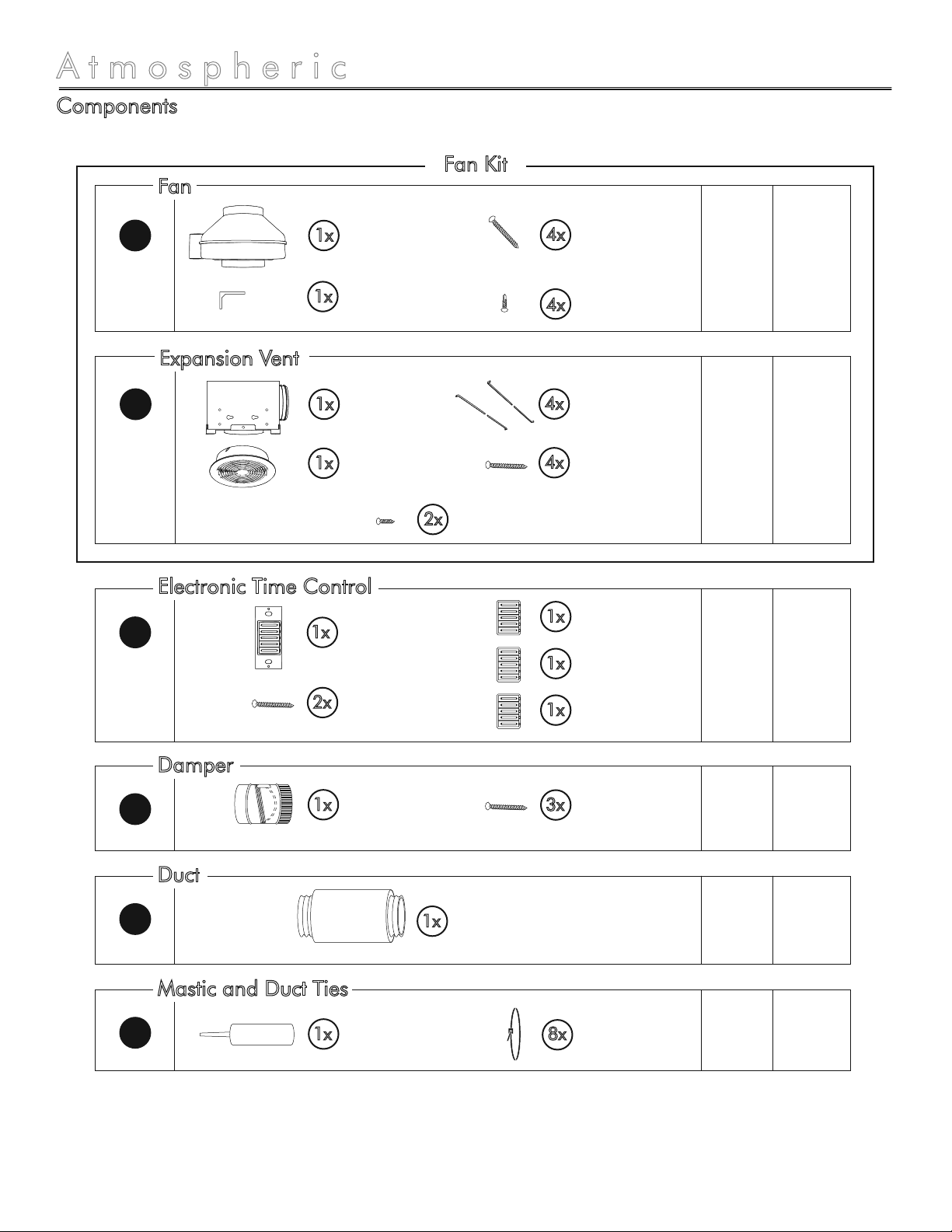
Components
2
1x Electronic Time
Control
1x Timer Face (White)
(Pre-installed)
Damper, 6”1x
Spec
Page
Install
Page
1x 66-8
11 11 - 13
14 14
190 CFM
Exhaust Fan, 6”
1x Mounting Bracket
4x 1” Screws
4x 7/16” Screws
A
C
E
Flex Duct,
6”x25’
1x
H16 16 - 17
Mastic Tube
Net Contents: 1/12 Gallon
1x 8x Flex Duct Tie, 18”
3x Damper Screws
2x Mounting Screws
1x Timer Face (Ivory)
1x Timer Face (Almond)
Fan
Electronic Time Control
Damper
Duct
I16 16 - 17
Mastic and Duct Ties
1x 99-10
Expansion Vent
Housing, 6” duct
1x Expansion Vent
Grille
4x Hanger Bars
4x 1” Screws
2x 3/8” Short Screws
B
Expansion Vent
Fan Kit

Atmospheric 330 by BATHOLOGY
Components Continued
3
1x Slide Speed
Control
2x Mounting Screws 11 11 - 13
D
3x Wire Nuts
Slide Speed Control
Wall Vent, 6”
1x
Roof Cap, 6”
1x 15 15
F
15 15
G
Roof Cap
Wall Vent
Vent Options
Optional

by BATHOLOGY
Atmospheric 330
Typical Installation - Exterior Roof
A
B
C
D
E
F
H
I
Fan
Expansion Vent
Electronic Timer Control
Speed Slide Control
Damper
Roof Cap
Duct
Mastic and Ties
6 - 8
9 - 10
11 - 13
11 - 13
14
15
16 - 17
16 - 17
Page ID Product
Important: It is recommended that all electrical equipment be tested prior to installation.
4
F
A
H
E
D
C
B
Power Source
Accessible Area
Bath Area
Exterior Roof
H
by BATHOLOGY
Atmospheric 330
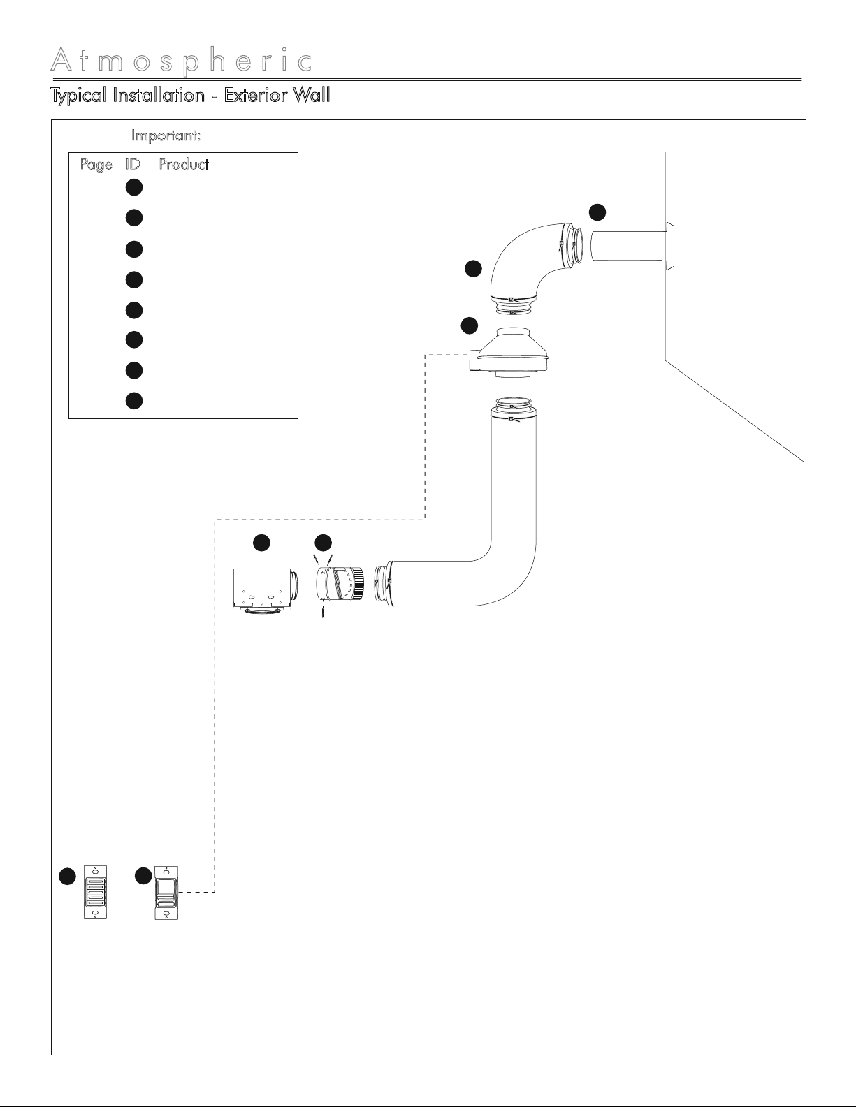
Typical Installation - Exterior Wall
Important: It is recommended that all electrical equipment be tested prior to installation.
5
H
G
A
E
D
C
B
Power Source
Accessible Area
Exterior Wall
Bath Area
A
B
C
D
E
G
H
I
Fan
Expansion Vent
Electronic Timer Control
Speed Slide Control
Damper
Wall Vent
Duct
Mastic and Ties
6 - 8
9 - 10
11 - 13
11 - 13
14
15
16 - 17
16 - 17
Page ID Product
by BATHOLOGY
6
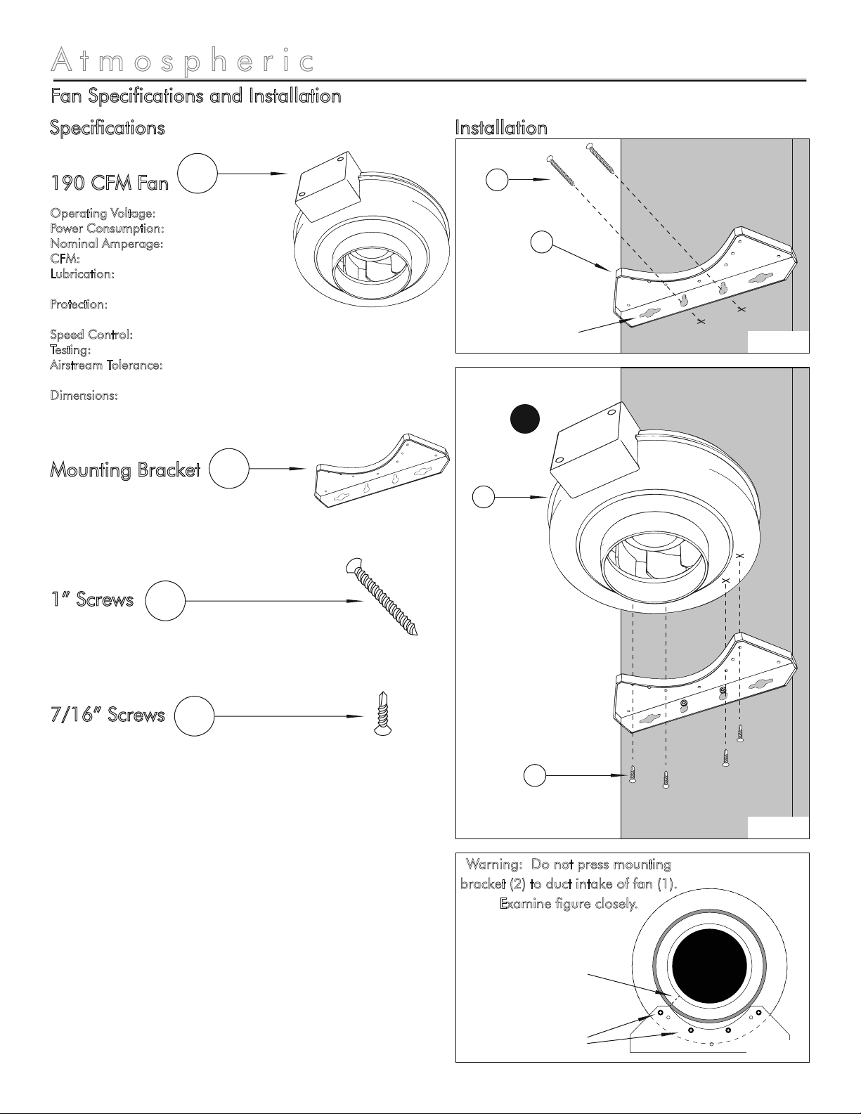
Fan Specifications and Installation
Atmospheric 330
190 CFM Fan
Operating Voltage: 120VAC
Power Consumption: 60W
Nominal Amperage: 0.52 Amps
CFM: 190 @ .20” W.G.
Lubrication: Permanently Lubricated
Sealed Ball Bearings
Protection: Automatic Reset Thermal
Overload Protection
Speed Control: 100% Speed Controllable
Testing: U.L. Listed; CSA Certified
Airstream Tolerance: Suitable for Airstream
Temperatures up to 140°F
Dimensions: 11-3/8” Diameter x 8” Length
1
Mounting Bracket 2
1” Screws 3
7/16” Screws 4
Stud /
Ceiling Joist
Stud /
Ceiling Joist
1” Screw
3
Mounting
Bracket
2
190 CFM
Fan
1
7/16” Screw
4
A
Figure 1
Figure 2
Specifications
Warning: Do not press mounting
bracket (2) to duct intake of fan (1).
Examine figure closely.
Installation
II
III III
Mount fan to mounting
bracket through slots
“I” and “III” of each side
Mounting Bracket spaced
correctly from duct intake
Figure 3
Use exterior slots for
horizontal installation
by BATHOLOGY
7
Fan Installation
Atmospheric 330
Installation Considerations
Warning: For your safety, read and understand
instructions completely before starting. Before
wiring to power supply, turn off electricity at the
fuse or circuit breaker box. Make sure electrical
service to fan is locked in “OFF” position.
Note: Prior to installation, consider the placement
of the 190 CFM Fan carefully, taking into account
the location of electrical, plumbing, and other
fixtures.
Note: All units are suitable for use with solid-state
speed controls
Note: This unit has rotating parts and safety
precautions should be exercised during
installation, operation and maintenance.
Caution: For general ventilation use only. Do not
use to exhaust hazardous or explosive materials
and vapors.
Note: All wiring must be done in accordance with
National Electrical Code and local building code.
Note: The combustion air-flow needed for safe
operation of fuel burning equipment may be
affected by this unit’s operation. Follow the
heating equipment manufacturer’s guidelines and
safety standards such as those published by the
National Fire Protection Association (NFPA), the
American Society of Heating, Refrigeration, and
Air Conditioning Engineers (ASHRAE).
Note: Exhaust fans must always be vented to the
outdoors.
Note: Acceptable for use over a bathtub or
shower.
Warning: NEVER place a switch where it can be
reached from a tub or shower.
Warning: For installation over a tub or shower,
power source must be externally switched GFCI
circuit and must be installed in accordance with
local and building codes.
-
-
-
-
-
-
-
-
-
-
-
When selecting fan (1) mounting location, the
following criteria should be considered: a)
mounting to minimize noise generated by fan
operation; b) service accessibility.
Mounting to minimize noise generated by fan
operation: Mounting the fan (1) as far as
possible from the intake point will minimize fan
operating noise from being transmitted back
through the duct work. Insulated flexible type
duct work (recommended for all bathroom
exhaust applications) will result in much quieter
operation. It is recommended that a minimum
8’ of insulated flexible ducting be used between
any expansion vent and fan (1) for low noise
level.
Service accessibility: Fan (1) location should
allow sufficient access for service.
1.
a)
b)
Installation
-
-
Warning: Check voltage at the fan to see if it
corresponds to the motor nameplate.
Warning: Guards must be installed when fan is
within reach of personnel or within seven (7) feet
of working level or when deemed advisable for
safety.
For safety purposes, use safety goggles
at all times.
Check for piping/electrical before
cutting or drilling.
If there is any risk of uninsulated
electrical connections in your wall/ceiling area, use
insulating gloves.
Before wiring to power supply, turn off
electricity at the fuse or circuit breaker box.
Important: It is recommended that all electrical
equipment be tested prior to installation.
by BATHOLOGY
8
Fan Installation
Atmospheric 330
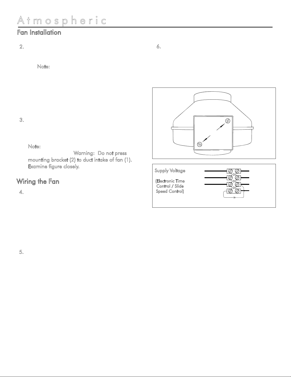
Remove the screws securing the terminal box
cover plate located on the side of the fan (1)
(see figure 3). All fan motor connections are
pre-wired to an electrical terminal strip. A 3/8”
romex type cable restraint connector will be
needed to secure the wiring through the
knockout provided on the side of the terminal
box.
Bring incoming electrical service through the
romex connector and the fan knockout. Be
sure to place the connector nut over the wiring
coming into the terminal box. There are two
open ports on the terminal strip. Using a small
regular screwdriver, tighten the neutral (white)
wire of the incoming supply under the open
terminal strip port labeled “N”. Tighten the line
(black) wire of the incoming supply under the
open terminal strip port labeled “L”. Since the
fan motor is isolated within a plastic housing,
grounding is not necessary (see figure 4).
4.
5.
Secure the romex connector. Secure the
incoming supply with the romex connector.
Replace the fan terminal box cover. All fan
motor and capacitor connections have been
pre-wired from the factory. No additional fan
wiring is necessary.
6.
Using the 1” wood screws (3) provided, attach
the fan mounting bracket (2) to a support beam
at the selected location (see figure 1 on page
6). Note: Fan (1) mounting can be at any
point along the duct and in any angle;
however, vertical mounting is recommended to
reduce condensation buildup in the fan (1). If a
horizontal installation is necessary and
condensation buildup may pose a problem,
wrap insulation around the fan (1).
Attach fan (1) to the mounting bracket (2) with
the four 7/16" sheet metal screws (4) provided,
making sure the wiring box is positioned for
easy access (see figure 2 and 3 on page 6).
Note: Screws are self tapping and do not
require pilot holes. Warning: Do not press
mounting bracket (2) to duct intake of fan (1).
Examine figure closely.
2.
3.
Wiring the Fan
Screws
Figure 3
Figure 4
Ground Green/Yellow
Blue
Black
Brown
Capacitor
White (N)
Black (L)
Supply Voltage
(Electronic Time
Control / Slide
Speed Control)
by BATHOLOGY
Housing Specifications and Installation
Atmospheric 330
Installation Considerations
9
Specifications Installation
Expansion Vent
Housing
Expansion Vent
Grille
Expansion Vent
Hanger Bars
Duct Connection: 6”
Rough-in Cutout: 6”
1
2
3
For safety purposes, use safety goggles
at all times.
Check for piping/electrical before
cutting or drilling.
If there is any risk of uninsulated
electrical connections in your wall/ceiling area, use
insulating gloves.
Warning: For your safety, read and understand
instructions completely before starting.
Note: Prior to installation, consider the placement of
the Expansion Vent carefully, taking into account the
location of electrical, plumbing, and other fixtures.
Note: The combustion air-flow needed for safe
operation of fuel burning equipment may be affected by
this unit’s operation. Follow the heating equipment
manufacturer’s guidelines and safety standards such as
those published by the National Fire Protection
Association (NFPA), the American Society of Heating,
Refrigeration, and Air Conditioning Engineers
(ASHRAE).
Note: Exhaust fans must always be vented to the
outdoors.
-
-
-
-
6” Cutout
Ceiling
Material
2
Expansion
Vent
Grille
B
1
Expansion
Vent
Housing
Mounting Directly to Joist
Mounting Brackets to Joist
15/32” from
bottom edge
of joist.
Secure front and
back hangar bars
with 3/8” screws
Position Locator Tabs
flush with bottom
edge of joist
Screws
B
B
Figure 1
Figure 2
Figure 3
1
Expansion Vent
Housing
1
Expansion Vent
Housing
3
Expansion Vent
Hanger Bars

by BATHOLOGY
10
Expansion Ventilation Installation
Atmospheric 330
1.
2.
3.
4.
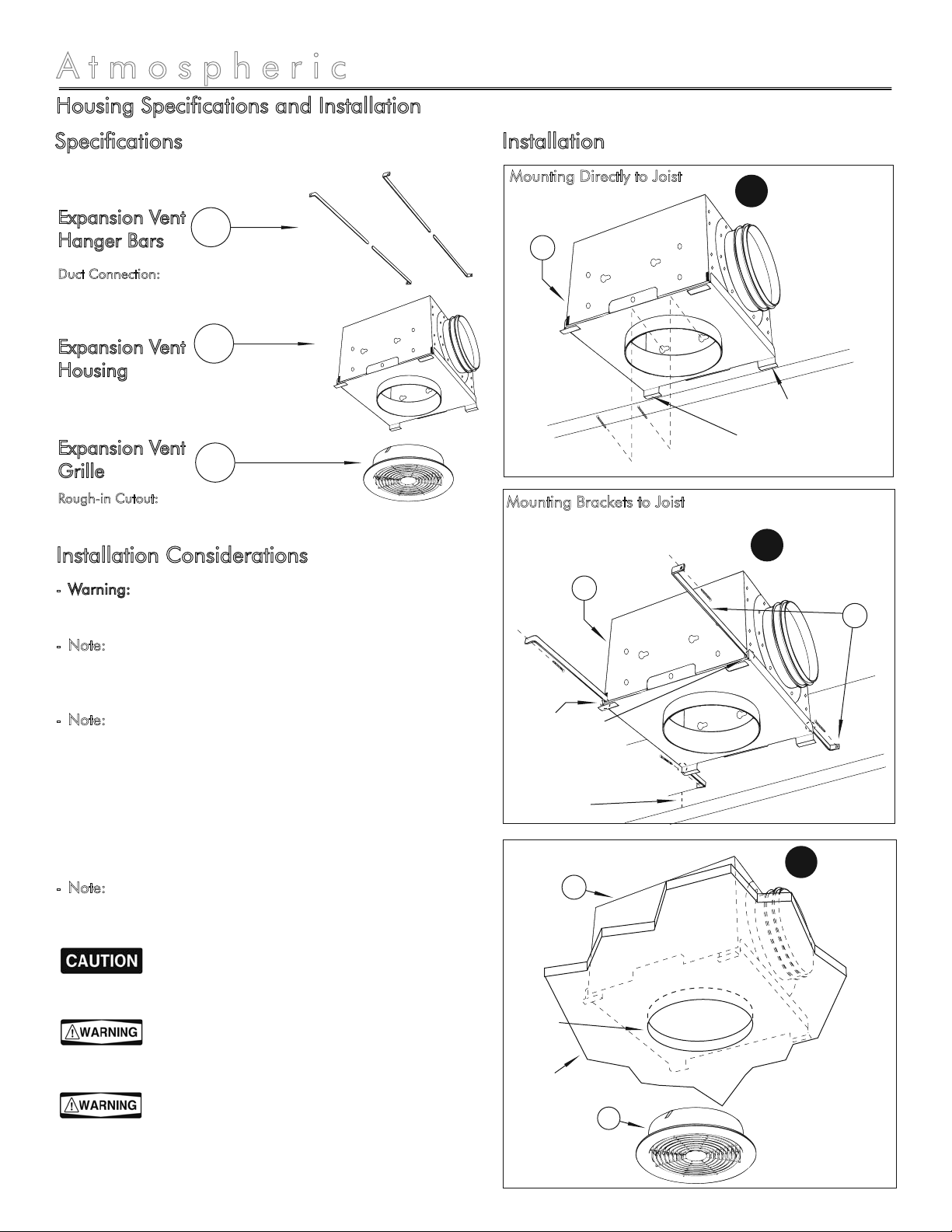
Based on the bathroom layout and fixtures,
plan the location of the expansion vent grilles
(2) for the most effective ventilation.
Mount expansion vent housing (1) directly to
the ceiling joist using screws and keyhole slots.
Locator tabs on housing should be flush with
the bottom edge of the ceiling joist for correct
positioning of the unit once ceiling material is
installed (see figure 1 on page 9).
OR
Use the expansion vent hanger bars (3) to
suspend the expansion vent housing (1)
between ceiling joists. For correct positioning,
hanger bars (3) should be positioned 15/32"
up from the bottom edge of the ceiling joist.
Secure hanger bars with 3/8” screws (see figure
2 on page 9).
Note: Expansion vent hanger bars (3) can be
used on ceiling joists up to 16" on center.
Note: If ceiling material is thicker than 5/8" the
locator tabs may be removed to allow the grille
collar to be flush with the finished ceiling
material.
Note: Designed for 1-1/8” ceiling material
maximum.
Cut a 6" round hole for the expansion vent
grille (2).
Install the expansion vent grille (2) by pushing it
firmly into the steel collar until it is shouldered
by the ceiling material (see figure 3 on page 9).
Installation
by BATHOLOGY
11
Control Specifications and Installation
Atmospheric 330
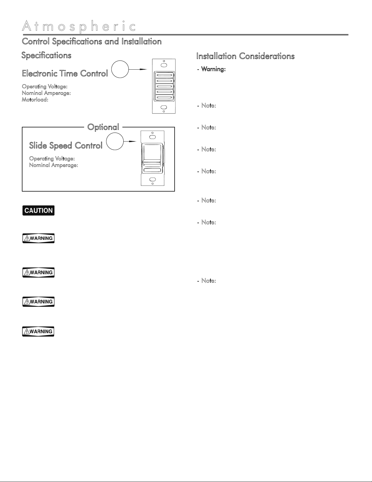
Electronic Time Control
Operating Voltage: 120VAC, 60Hz
Nominal Amperage: 20 Amps
Motorload: 1HP
1Warning: For your safety, read and understand
instructions completely before starting. Before wiring to
power supply, turn off electricity at the fuse or circuit
breaker box.
Note: All wiring must be done in accordance with
National Electrical Code and local building code.
Note: NEVER place a switch where it can be reached
from a tub or shower.
Note: Recommended minimum wall box depth is
2-1/2”.
Note: Maximum wire length from electronic time
control to all installed remote switches cannot exceed
300 ft (90m).
Note: Use these devices with copper or copper clad
wire only.
Note: When combinations of electronic time control /
slide speed control are installed in a ganged wall or
outlet box, derating is required. When two devices are
mounted in a ganged box, the maxminum load per
device shall not exceed 4A or 500 watts. When three or
more devices are mounted in a ganged box, the
maximum load shall not exceed 3A or 400 watts.
Note: The electronic time control and the slide speed
control should be installed 48” above the floor, on a
vertical wall, convenient for user operation.
-
-
-
-
-
-
-
-
For safety purposes, use safety goggles
at all times.
Check for piping/electrical before
cutting or drilling.
Electrical components are not
waterproof.
If there is any risk of uninsulated
electrical connections in your wall/ceiling area, use
insulating gloves.
Before wiring to power supply, turn off
electricity at the fuse or circuit breaker box.
Installation Considerations
Slide Speed Control
Operating Voltage: 120VAC, 60Hz
Nominal Amperage: 5 Amps
2
Optional
Specifications

by BATHOLOGY
12
Atmospheric 330
Control Installation
Hot (Black)
Line 120VAC
60Hz
Line 120VAC
60Hz
Line 120VAC
60Hz
Line 120VAC
60Hz
Neutral (White)
Black
Green
Ground Black
White
White
Red
Fan
Timer / Fan Wiring
Timer / Light / Fan Wiring
Hot (Black)
Neutral (White)
Black
Black
White
White
Black
White
Red Black
Fan
Vent
Lights
Timer / Slider / Fan Wiring
Hot (Black)
Neutral (White)
Black
Black
White
White
Red Black Black
Fan
Timer / Lights / Slider / Fan Wiring
Hot (Black)
Neutral (White)
Black
Black
White
White
Black
White
Red Black Black
Fan
Vent
Lights
Green
Ground
Green
Ground
Green
Ground
Green
Ground
Green
Ground
C
C
C
CD
D
B
B
A
A
A
A
by BATHOLOGY
13
Control Installation
Atmospheric 330
Press timer button based on desired operation time.
This will enable use of the slide speed control (B), as
well as illuminate expansion vent lighting if present.
Slide bar control up or down for desired fan rotation
speed. ON/OFF rocker switch will turn fan ON at
speed set by slide bar.
To change faceplate of electronic time control
(1), push in the side of the faceplate at the tabs
to release. With desired faceplate, line up tabs
and press in sides one at a time to attach.
Remove pre-cut 3/8” of insulation from each
circuit conductor. Make sure the ends of wires
are straight.
Install electronic time control (1) and slide
speed control (2) into double gang box, two
single gang boxes, or single gang box as
installation permits.
Connect wires per applicable wiring diagram
on previous page: Twist strands of each lead
tightly together and, with circuit conductors,
push firmly into appropriate wire connector.
Screw connectors on clockwise making sure no
bare conductors show below the wire
connectors. Secure each connector with
electrical tape.
Restore power at circuit breaker or fuse.
1.
2.
3.
4.
5.
Installation
Operation
Important: It is recommended that all electrical
equipment be tested prior to installation.
by BATHOLOGY
14
Damper Specifications / Installation
Atmospheric 330
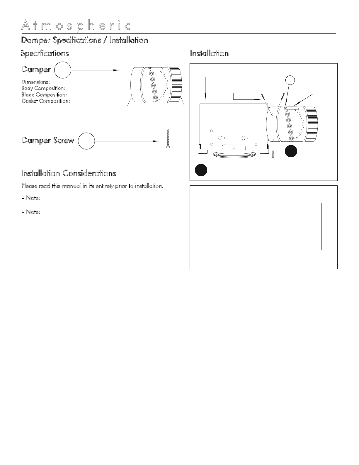
Damper
Dimensions: 6” Diameter x 6” Length
Body Composition: 28 guage galvanized steel
Blade Composition: Aluminum blades
Gasket Composition: Foam
1
InstallationSpecifications
Damper Screw 2
Note: Output end should never be lower than input.
Note: Follow all applicable codes and standards.
-
-
Installation Considerations
Please read this manual in its entirety prior to installation.
Label must
be upright
Screw Damper Input to
Expansion Vent Housing
Figure 1
Damper
Expansion Vent
1
Figure 2
B
E
Input Output
Install with this label up. Output end
should never be lower than input.
>>>>> AIR FLOW >>>>>
>>>>> AIR FLOW >>>>>

by BATHOLOGY
15
Roof Cap / Wall Vent Specifications and Installation
Atmospheric 330
Roof Cap, 6” 1
Wall Vent, 6” 2
Specifications Installation
Note: Do not install the roof cap on a flat roof!
Note: Follow all applicable codes and standards.
-
-
Installation Considerations
Please read this manual in its entirety prior to installation.
F
G
A
A
H
H
Roof Cap
1
Composition: Galvanized Steel
Rough-in Cutout: 6-1/8”
Duct Connection: 6”
Cap Dimensions: 10-3/4”L x 8-1/4”W x 5-1/4”H
Grille Composition: Plastic
Extension Composition: Galvanized Steel
Rough-in Cutout: 6-1/8”
Duct Connection: 6”
Cap Dimensions: 8-1/8”L x 8-1/8”W x 7/16”H
Duct Extension: 6” Diameter x 12” Length
Wall Vent
2

by BATHOLOGY
16
Duct Specifications and Installation
Atmospheric 330
Flex Duct, 6”
Dimensions: 6” Diameter x 25’ Length
Insulation: Fiberglass
Outer Cover: Tri-directional, scrim reinforced grey polyester
Testing: U.L. Listed, Suitable for Wet Locations
R-Value: 4.2
Rated Positive Pressure: 10“ w.g. per UL-181
Maximum Positive: 6” w.g.
Maximum Negative: 3/4” w.g.
Maximum Velocity: 5000 FPM
Maximum Operating Temperatures: -20°F to 140°F
Continuous (@ maximum pressure)
1
Compliance: UL-181-B
Flex Duct Tie, 36” 2
Compliance: UL-181-B
Net Contents: 1/12 Gallon
Mastic Tube 3
100 CFM Fan
Exhaust to Roof
Cap or Wall Vent
Damper, 4”
Expansion Vent
Flex Duct
Tie, 36”
2
Flex Duct,
6” x 25’
1
Figure 1
Figure 2
Figure 3
Fold back outer
cover and insulation
Pull outer cover and insulation
to completely cover the fitting.
Apply Mastic (3)
over fitting and / or
inside the inner liner
Slide inner liner
at least 1” over fitting
Secure inner liner
to fitting with 36” tie (2)
Secure outer cover and
insulation to fitting
with 36” tie (2)
Apply additional mastic (3)
over the connection
Specifications Installation
Minimum radius =
the diameter of
flexible ducting used
Install duct fully extended. Do not install
in a compressed state or use excess lengths.
by BATHOLOGY
17
Duct Installation
Atmospheric 330
After desired length is determined, cut
completely around the through duct with
multipurpose tool. Fold back outer cover and
insulation. Apply mastic over fitting and / or
inside the inner liner (see figure 2 and 3 on
page 16).
Slide at least 1” of inner liner over fitting. Seal
inner lining to collar. Secure connection with tie
placed over the inner lining.
Pull outer cover and insulation back over inner
lining. Secure connection with tie placed over
the outer cover and insulation.
1.
2.
3.
Note: Do not use “outdoors” or install where duct
can be exposed to direct sunlight. Prolonged
exposure may cause degradation of vapor barrier.
Note: Do not install where duct can be exposed to
UV radiation from bio-treatment lamps within the
HVAC system. Exposure may cause degradation of
the inner core.
Note: Not not exceed published pressure or
temperature limits.
Note: Do not use duct to hang or support any
diffuser, register, or other equipment during
installation.
Note: Do not use screws or barbed fitting to make
connections on ducts with plain ends.
Note: Duct should be supported at 5’ maximum
intervals unless resting on ceiling joists or truss
supports. 1/2” sag per foot of support spacing is
permissible. Vertically installed duct shall be
stablized by support straps at a maximum of 6’ on
center.
Note: Do not use on oval collars for medium or
high pressure.
Warning: Insulated flexible duct contains fiber glass
wool which has been classified as a possible cancer
hazard by inhalation. Fiber glass wool may cause
temporary irritation to skin, eyes, and respiratory
tract.
Note: Use a poperly fitted NIOSH or MSHA
approved dust/mist respirator.
Note: Avoid breathing fiber glass duct.
Note: Avoid contact with skin and eyes.
Note: Wear long-sleeved, loose fitting clothing,
gloves and eye protection.
Note: Wash with soap and warm water after
handling.
Note: Wash work clothes separately and rinse
washer thoroughly.
Note: All tapes, mastics, and non-metallic fasteners
used for field installation of flexible ducts shall be
listed and labeled to Standard UL-181-B - Closure
Systems for use with Flexible Air Ducts and Air
Connectors. Non-metallic fasteners are limited to
6” w.g. maximum positive pressure.
Note: It is recommended a minimum 8’ of
insulated flexible ducting be used between any
expansion vent and fan for low noise level.
Note: A multipurpose tool is recommended for duct
installation.
Note: Follow all applicable codes and standards.
Installation Considerations
Installation
900-0514-0713
BATHOLOGY
rediscover bathing
A division of Bathing Brands, Inc.
www.Bathology.com 847-465-1070
Table of contents
Other Bathology Fan manuals


