Bathology Atmospheric 310 User manual

BATHOLOGY
rediscover bathing
Atmospheric 310
In-Shower Ventilation
Installation and Operation Manual
Atmospheric 310 by BATHOLOGY
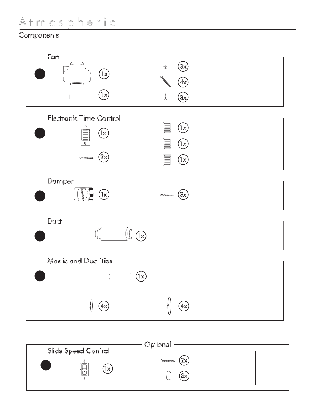
Components
1x Electronic Time
Control
1x Timer Face (White)
(Pre-installed)
Damper, 4”
1x
Spec
Page
Install
Page
1x 66-8
13 13 - 15
16 16
100 CFM
Exhaust Fan, 4”
1x Mounting Bracket
3x Vibration Isolation
Grommet
4x 1” Screws
3x 7/16” Screws
A
C
E3x Damper Screws
2x Mounting Screws
1x Timer Face (Ivory)
1x Timer Face (Almond)
2
1x Slide Speed
Control
2x Mounting Screws 13 13 - 15
D
3x Wire Nuts
Electronic Time Control
Fan
Damper
Slide Speed Control Optional
HFlex Duct,
4”x25’
1x 18 18 - 19
Mastic Tube,
Net Contents: 1/12 Gallon
1x
Flex Duct Tie, 36”
4x
Flex Duct Tie, 18”
4x
Duct
K18 18 - 19
Mastic and Duct Ties

Atmospheric 310 by BATHOLOGY
Components Continued
3
Wall Vent, 4”
1x
Roof Cap, 4”
1x
Spec
Page
Install
Page
1x 9 9 - 12
Expansion Vent
Housing, 4” duct
1x Expansion Vent
Grille
4x Hanger Bars
4x 1” Screws
2x 3/8” Short Screws
B
17 17
F
17 17G
1x 9 9 - 12
Expansion Vent
Housing, 4” duct
1x Expansion Vent
Halogen Light
1x Expansion Vent
Grille
4x Hanger Bars
4x 1” Long Screws
2x 3/8” Short Screws
B
1x Expansion Vent
LED Light
1x Expansion Vent
Grille
1x 9 9 - 12
Expansion Vent
Housing, 4” duct 4x Hanger Bars
4x 1” Long Screws
2x 3/8” Short Screws
B
No Light
Roof Cap
Wall Vent
Halogen
LED
Vent Options
Expansion Vent Options

by BATHOLOGY
Atmospheric 310
Typical Installation - Exterior Roof
A
B
C
D
E
F
H
Fan
Expansion Vent
Electronic Timer Control
Speed Slide Control (Optional)
Damper
Roof Cap
Duct
6 - 8
9 - 12
13 - 15
13 - 15
16
17
18 - 19
Page ID Product
Important: It is recommended that all electrical equipment be tested prior to installation.
4
I
F
A
H
H
E
D
C
B
Power Source
Run for Optional Expansion Vent Lights
(Optional)
Accessible Area
Bath Area
Exterior Roof
by BATHOLOGY
Atmospheric 310
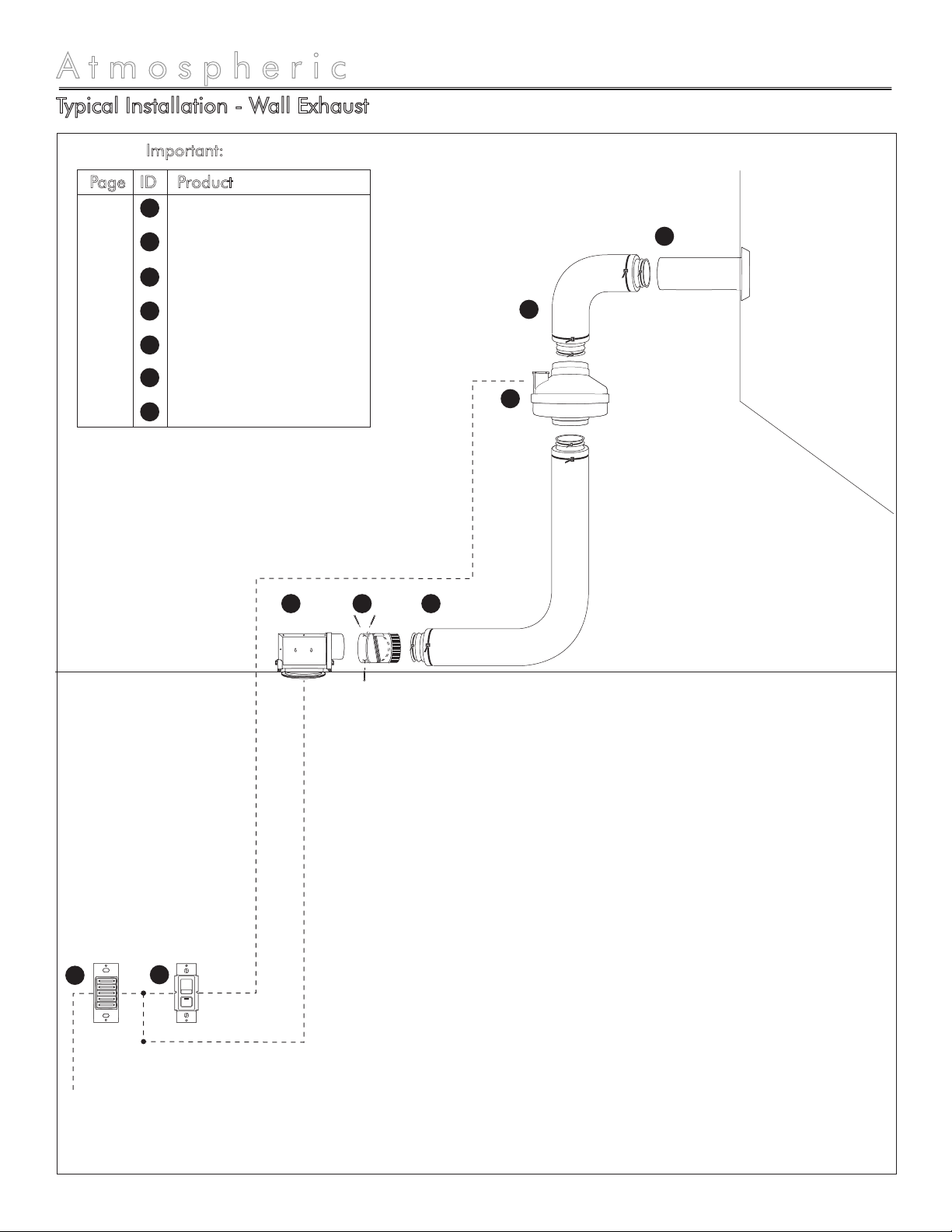
Typical Installation - Wall Exhaust
Important: It is recommended that all electrical equipment be tested prior to installation.
5
G
A
H
D
C
Power Source
Run for Optional Expansion Vent Lights
Accessible Area
Exterior Wall
Bath Area
A
B
C
D
E
G
H
Fan
Expansion Vent
Electronic Timer Control
Speed Slide Control (Optional)
Damper
Wall Vent
Duct
6 - 8
9 - 12
13 - 15
13 - 15
16
17
18 - 19
Page ID Product
H
E
B

by BATHOLOGY
6
Fan Specifications and Installation
Atmospheric 310
N
L
Black
White
Blue
Brown
Black / Red
Red
100 CFM Fan
Operating Voltage: 120VAC
Power Consumption: 21.1W
Nominal Amperage: 0.18 Amps
CFM: 100 @ .20” W.G.
Lubrication: Permanently Lubricated
Sealed Ball Bearings
Protection: Automatic Reset Thermal
Overload Protection
Speed Control: 100% Speed Controllable
Testing: U.L. Listed; CSA Certified
Airstream Tolerance: Suitable for Airstream
Temperatures up to 140°F
Dimensions: 9-1/2” Diameter x 10” Length
1
Mounting Bracket 2
Vibration Isolation
Grommet 3
1” Screws 4
7/16” Screws 5
Stud /
Ceiling Joist
Stud /
Ceiling Joist
1” Screw
4
Mounting
Bracket
2
Vibration Isolation
Grommet
3
100 CFM
Fan
1
7/16” Screw
5
Supply from Electronic Timer Control / Slide Speed Control
A
Figure 1
Figure 2
Specifications Installation

by BATHOLOGY
7
Fan Installation
When selecting fan (1) mounting location, the
following criteria should be considered: a)
mounting to minimize noise generated by fan
operation; b) service accessibility.
Mounting to minimize noise generated by fan
operation: Mounting the fan (1) as far as
possible from the intake point will minimize fan
operating noise from being transmitted back
through the duct work. Insulated flexible type
duct work (recommended for all bathroom
exhaust applications) will result in much quieter
operation. It is recommended that a minimum
8’ of insulated flexible ducting be used between
any expansion vent and fan (1) for low noise
level.
Service accessibility: Fan (1) location should
allow sufficient access for service.
1.
a)
b)
Atmospheric 310
Installation Considerations
Installation
Warning: For your safety, read and understand
instructions completely before starting. Before
wiring to power supply, turn off electricity at the
fuse or circuit breaker box. Make sure electrical
service to fan is locked in “OFF” position.
Note: Prior to installation, consider the placement
of the 100 CFM Fan carefully, taking into account
the location of electrical, plumbing, and other
fixtures.
Note: All units are suitable for use with solid-state
speed controls
Note: This unit has rotating parts and safety
precautions should be exercised during
installation, operation and maintenance.
Caution: For general ventilation use only. Do not
use to exhaust hazardous or explosive materials
and vapors.
Note: All wiring must be done in accordance with
National Electrical Code and local building code.
Note: The combustion air-flow needed for safe
operation of fuel burning equipment may be
affected by this unit’s operation. Follow the
heating equipment manufacturer’s guidelines and
safety standards such as those published by the
National Fire Protection Association (NFPA), the
American Society of Heating, Refrigeration, and
Air Conditioning Engineers (ASHRAE).
Note: Exhaust fans must always be vented to the
outdoors.
Note: Acceptable for use over a bathtub or
shower.
Warning: NEVER place a switch where it can be
reached from a tub or shower.
Warning: For installation over a tub or shower,
power source must be externally switched GFCI
circuit and must be installed in accordance with
local and building codes.
-
-
-
-
-
-
-
-
-
-
-
-
-
Warning: Check voltage at the fan to see if it
corresponds to the motor nameplate.
Warning: Guards must be installed when fan is
within reach of personnel or within seven (7) feet
of working level or when deemed advisable for
safety.
For safety purposes, use safety goggles
at all times.
Check for piping/electrical before
cutting or drilling.
If there is any risk of uninsulated
electrical connections in your wall/ceiling area, use
insulating gloves.
Before wiring to power supply, turn off
electricity at the fuse or circuit breaker box.
Important: It is recommended that all electrical
equipment be tested prior to installation.

by BATHOLOGY
8
Fan Installation
Atmospheric 310
Remove the screws securing the terminal box
cover plate located on the side of the fan (1)
(see figure 3). All fan motor connections are
pre-wired to an electrical terminal strip. A 3/8”
romex type cable restraint connector will be
needed to secure the wiring through the
knockout provided on the side of the terminal
box.
Bring incoming electrical service through the
romex connector and the fan knockout. Be
sure to place the connector nut over the wiring
coming into the terminal box. There are two
open ports on the terminal strip. Using a small
regular screwdriver, tighten the neutral (white)
wire of the incoming supply under the open
terminal strip port labeled “N”. Tighten the line
(black) wire of the incoming supply under the
open terminal strip port labeled “L”. Since the
fan motor is isolated within a plastic housing,
grounding is not necessary (see figure 4).
4.
5.
Secure the romex connector. Secure the
incoming supply with the romex connector.
Replace the fan terminal box cover. All fan
motor and capacitor connections have been
pre-wired from the factory. No additional fan
wiring is necessary.
6.
Using the 1” wood screws (4) provided, attach
the fan mounting bracket (2) to a support beam
at the selected location (see figure 1 on page
6). Note: Fan (1) mounting can be at any
point along the duct and in any angle;
however, vertical mounting is recommended to
reduce condensation buildup in the fan (1). If a
horizontal installation is necessary and
condensation buildup may pose a problem,
wrap insulation around the fan (1).
Attach fan (1) to the mounting bracket (2) with
the three 7/16" sheet metal screws (5)
provided, making sure the wiring box is
positioned for easy access (see figure 2 on
page 6). Note: Bracket (2) is provided with
rubber vibration isolation grommets (3) to
prevent the transmission of sound through the
structure. Be careful not to overtighten. Also,
care should be taken not to strip the plastic
housing. Screws (5) are selftapping and do not
require pilot holes. However, pilot holes no
larger than 3/32" are recommended.
2.
3.
Wiring the Fan
Screws
N
L
Figure 4
Figure 3
Black
White Blue
Brown
Black / Red
Red
Supply from Electronic Timer Control / Slide Speed Control

by BATHOLOGY
Housing Specifications and Installation
Atmospheric 310
Installation Considerations
9
Specifications
For safety purposes, use safety goggles
at all times.
Check for piping/electrical before
cutting or drilling.
Some electrical components are not
waterproof.
If there is any risk of uninsulated
electrical connections in your wall/ceiling area, use
insulating gloves.
Before wiring to power supply, turn off
electricity at the fuse or circuit breaker box.
Expansion Vent
Housing
Expansion Vent
Grille
Expansion Vent
Hanger Bars
Duct Connection: 4”
Rough-in Cutout: 6”
1
2
Expansion Vent
Grille
Rough-in Cutout: 6”
2
Halogen Light
3
Duct Connection: 4”
Operating Voltage: 120VAC, 60Hz
Nominal Amperage: .42 Amps
Expansion Vent
Housing
Expansion Vent
Hanger Bars
1
3
Expansion Vent
Grille
Rough-in Cutout: 6”
2
LED Light
Duct Connection: 4”
Operating Voltage: 120VAC, 60Hz
Expansion Vent
Housing
Expansion Vent
Hanger Bars
1
3
Expansion Vent Options
No Light
LED
Halogen
Lumens: 470
Color Temperature: 3000K
Warning: For your safety, read and understand
instructions completely before starting. Before wiring to
power supply, turn off electricity at the fuse or circuit
breaker box. Make sure electrical service to fan is
locked in “OFF” position.
Note: Prior to installation, consider the placement of
the Expansion Vent carefully, taking into account the
location of electrical, plumbing, and other fixtures.
Note: All wiring must be done in accordance with
National Electrical Code and local building code.
Note: The combustion air-flow needed for safe
operation of fuel burning equipment may be affected by
this unit’s operation. Follow the heating equipment
manufacturer’s guidelines and safety standards such as
those published by the National Fire Protection
Association (NFPA), the American Society of Heating,
Refrigeration, and Air Conditioning Engineers
(ASHRAE).
Note: Exhaust fans must always be vented to the
outdoors.
Warning: NEVER place a switch where it can be
reached from a tub or shower.
Warning: For installation over a tub or shower, power
source must be externally switched GFCI circuit and
must be installed in accordance with local and building
codes.
-
-
-
-
-
-
-
by BATHOLOGY
10
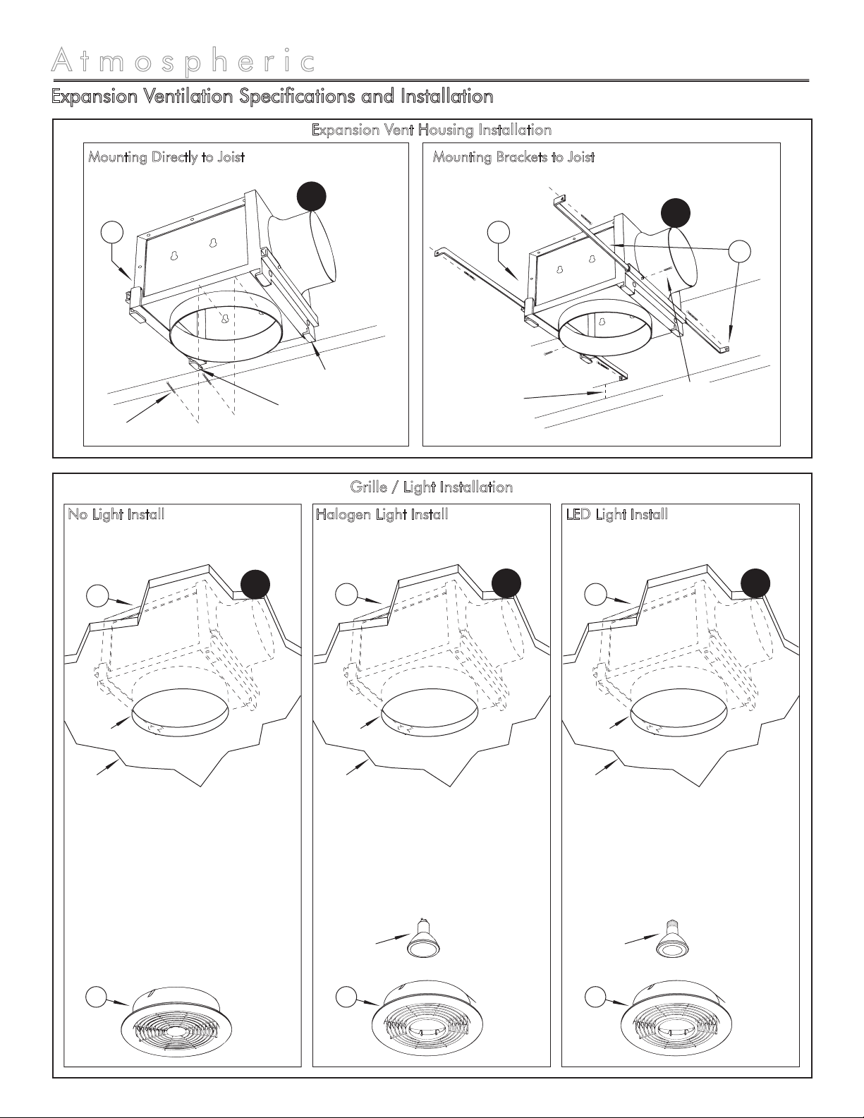
Expansion Ventilation Specifications and Installation
Atmospheric 310
Mounting Directly to Joist Mounting Brackets to Joist
Expansion Vent Housing Installation
Grille / Light Installation
13/16” from
bottom edge
of joist.
Position Locator Tabs
flush with bottom
edge of joist
Halogen
Light
LED
Light
B
B
Anti-slide
locking screw
Figure 1 Figure 2
1
Expansion Vent
Housing
1
Expansion Vent
Housing
3
Expansion Vent
Hanger Bars
Screws
LED Light Install
2
Expansion
Vent
Grille
Figure 5
Halogen Light Install
6” Cutout
Ceiling
Material
B
Figure 4
1
Expansion
Vent
Housing
2
Expansion
Vent
Grille
6” Cutout
Ceiling
Material
B
1
Expansion
Vent
Housing
No Light Install
6” Cutout
Ceiling
Material
2
Expansion
Vent
Grille
B
Figure 3
1
Expansion
Vent
Housing
Table of contents
Other Bathology Fan manuals


Popular Fan manuals by other brands

ELTA FANS
ELTA FANS H03VV-F installation guide

Hunter
Hunter 20714 Owner's guide and installation manual

Emerson
Emerson CARRERA VERANDA CF542ORB00 owner's manual

Hunter
Hunter Caraway Owner's guide and installation manual

Panasonic
Panasonic FV-15NLFS1 Service manual

Kompernass
Kompernass KH 1150 operating instructions


