Baton EVPOS-1TACA Operation manual

Owner's Operating Manual
EVPOS-1TACA Welding Positioner

Chapter 1: Introduction
A
W
B
Objective
Restriction of the work piece
1.1.1 The POS for MCA series positioner can be used welded, cut and grind, it has one table rotate and table angle move, the operator can be apt to
adjust the work piece position fast, enable him to finish the work and keep quality fast.
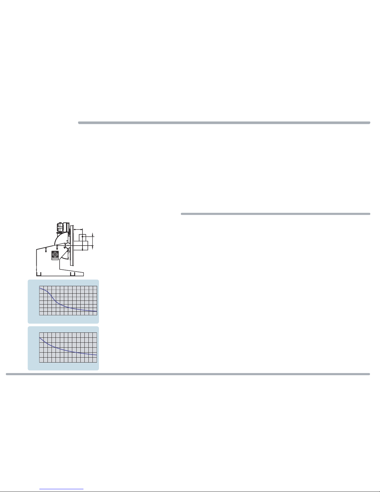
1.1.2.1 The weight or length of the work piece exceed designing limiting, please look at charts [Figure:1.2-1].
1.1.2 Forbid using the case:
1.1.2.2 The work piece does not have certain locking in table of EVPOS for MCA series positioner.
1.1.2.3 The scope of activities of the work piece has personnel or hinders things.
1.1.2.4 Have not imputed the machine to the ground or firm foundation.
Figure: 1.2-2
1.1
1.2
1.2.1 CAPABILITY
Page 1
0
200
400
600
800
1000
1200
1400
1600
020 40 60 80 100 120 140
0
200
400
600
800
1000
1200
30 40 50 60 70 80 90 100
EVPOS-1TACA Positioner Eccentric Load
A : Eccentric Center (cm.)
W : Load (kg.)
EVPOS-1TACA Center of Gravity
B : Center of Gravity (cm.)
W : Load (kg.)
Structure
1.3
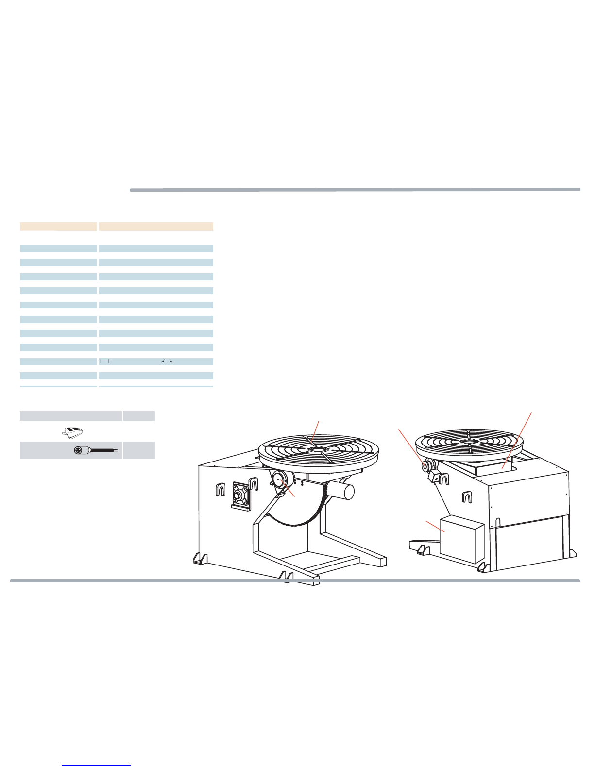
1.3.1 Specification
1.3.2 Standard Accessories 1.3.3 POS for ACA series Structure
Figure: 1.3-1 Figure: 1.3-2
Part Name Quantity
Pedal Switch 1
Welder start wire 1
Table
Controller
Angle limit switch adjustment unit
Rotation gearbox of table
Angle labelling
Page 2
Specification
Power
Table rotate motor
Capacity
Eccentricity
Center of Gravity
Table Dia.
Spindle Thru Hole
Table speed
Table angle
Table angle speed
Table angle motor
Table angle lock
Table rotate control
OverLap timer(Fixing point)
Timer (Fixing point)
Lap well timer (Fixing point)
Start / Crater arc timer
Arc way of the welder
Welding current
Table rotate control
Remote control
EVPOS-1TACA
V1:AC 220V / 20A / 50;60Hz / 3Ø
V2:AC 380V / 18A / 50Hz / 3Ø
DC 180V / 400W
1000Kg.
300mm.
300mm.
900mm.
120mm.
0.05-0.5 RPM
0° - 135°
55!sec / 135°
AC 0.5HP
Motor brake
inch / Hold / Overlap / Timer
0 - 99.9sec(display unit : 0.1sec)
0 - 999sec(display unit :1sec)
0 - 99.9sec(display unit : 0.1sec)
0 - 99.9sec(display unit : 0.1sec)
Standard(2 cycle) / Cater(4 cycle)
1000A / 100%
Pedal switch(The wire is 4M Cable)
Control line(The wire is 4M Cable)
S
peci
f
ication

Chapter 2: Safety

Safty Information
2.1.1 This document provides general safety instructions. Some information requires special attention for either safety or procedural reasons. Label with an appropriate heading WARNING and
CAUTION will be used throughout this manual. For example:
2.1.1.1 Failure to follow WARNING instruction could result in severe injury or death to the operator, a bystander or a person inspecting or repairing the machine.
2.1.1.3 Failure to follow DANGER instruction could result in severe injury or death to the operator, a bystander or a person inspecting or repairing the machine.
2.1.1.2 Failure to follow CAUTION instruction may result in injury to the operator, a bystander or a person inspecting or repairing the machine, or damage to the machine’s part and/or controller.
2.1.1.4 Failure to follow ATTENTION instruction may result in injury to the operator, a bystander or a person inspecting or repairing the machine, or damage to the machine’s part and/or controller.
WARNING
ATTENTION
2.1 Page 3

Safety Labels
Figure:2.2-2
Figure:2.2-1
WARNING ATTENTION
Fix machinery on the ground or the strong foundation.
When the mechanical table angle is moved or static, forbid having operators below the work piece.
Forbid operators on the mechanical table.
2.2 Page 4

Figure:2.3-3
Figure:2.3-7
Electrical Hazards And High Temperature
-HIGH TEMPERATUR Don’t Touch
HIGH TEMPERATURE Don’t Touch
-Electrical Hazard Label.
2.3
Figure:2.3-1 Figure:2.3-2
Page 5

Figure:2.4-3 Figure:2.4-4
carbon Brush the
contact area, do not
use oil.
Figure:2.4-7
Rotaing And Other
-ROTATING keep hands away.
2.4
Figure:2.4-1 Figure:2.4-2
Page 6
carbon Brush the
contact area, do not
use oil.
-Carbon Brush the contact area, do not use oil.
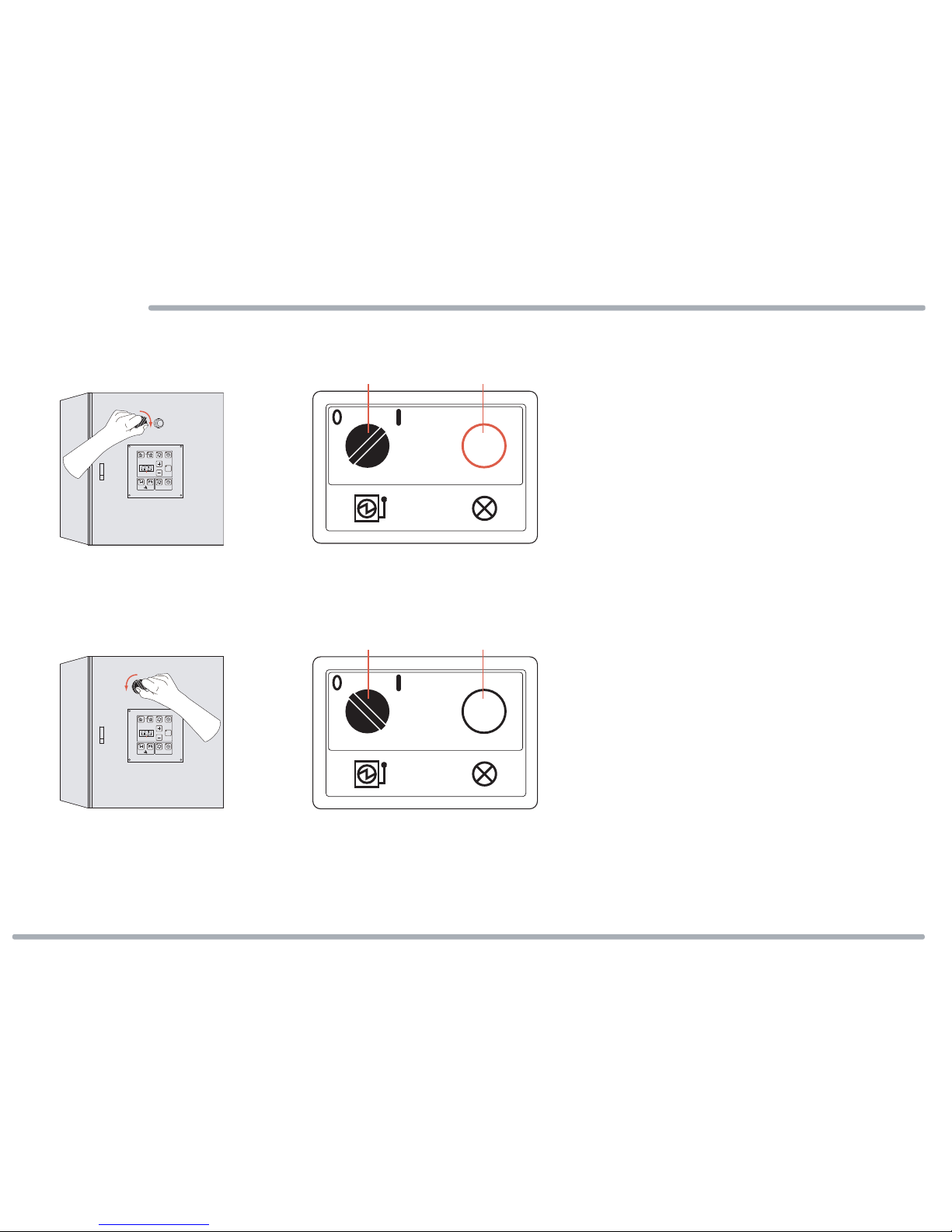
Power
2.5
Power ON
2.5.1
Power OFF
2.5.2
Figure:2.5-1
Figure:2.5-2
Page 7
Standard
Set
AUTOMODE
EVPA01
Crater
UNIT:0.1 sec
00.0 ~ 99.9 sec
Standard
Set
AUTOMODE
EVPA01
Crater
UNIT:0.1 sec
00.0 ~ 99.9 sec
Power switch Power lamp
I-ON
Power switch Power lamp
O-OFF
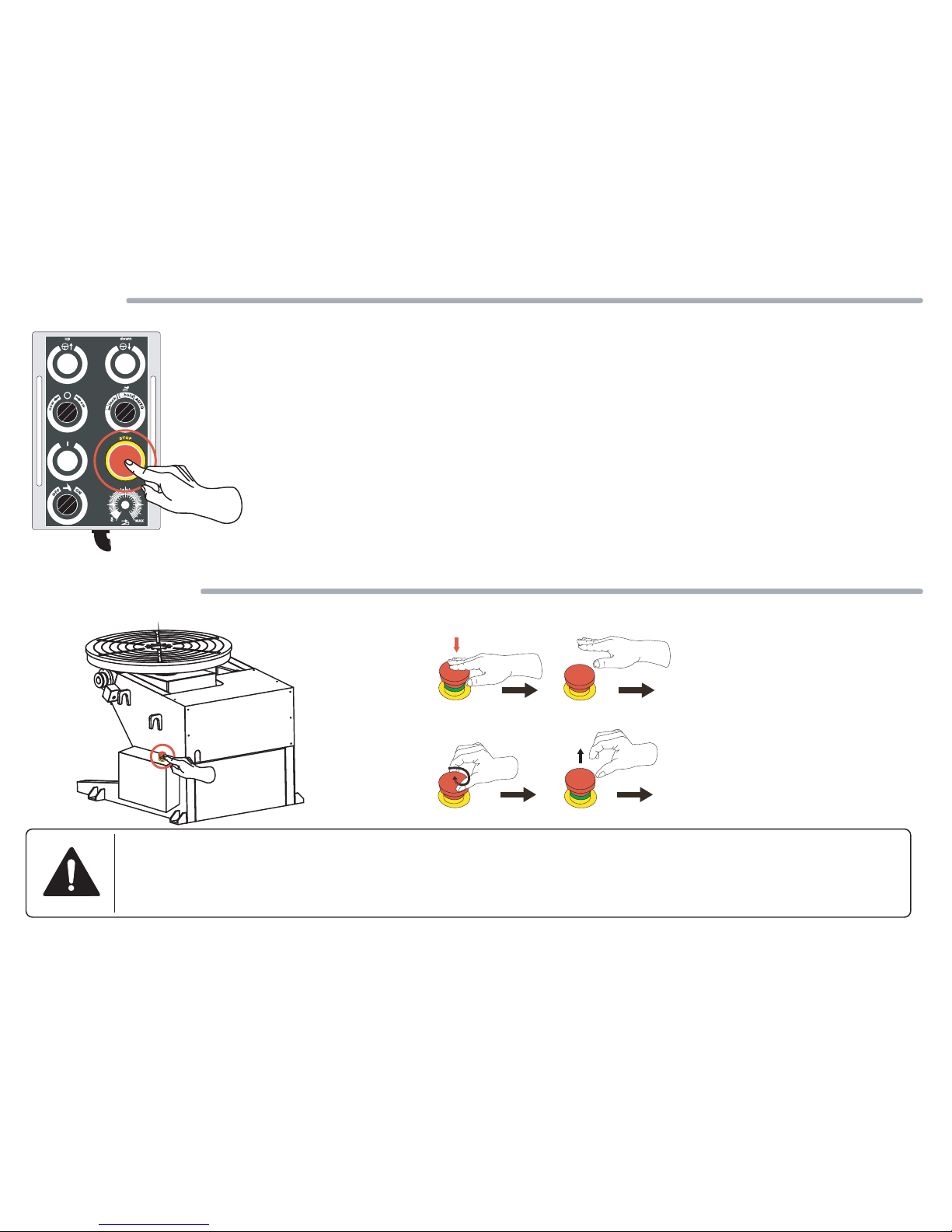
The stop result with continues, Reference page 31,32,41,42.
Stop
2.6
Emergency Stop
2.6-1
Page 8
1
0
2
0
3
0
4
0
5
0
6
0
7
0
8
0
9
0
E
M
E
R
G
E
N
C
E
M
E
R
G
E
N
C
E
M
E
R
G
E
N
C
E
M
E
R
G
E
N
C
E
M
E
R
G
E
N
C
The power and all control movements are closed at the same time.
The power and all control movements resume the function.
Emergency Stop
Release

2.7 Page 9
Figure:2.7-1
Figure:2.7-2
Figure:2.7-3
Figure:2.7-4
Figure:2.7-5
1
0
2
0
3
0
4
0
5
0
6
0
7
0
8
0
9
0
1
0
2
0
3
0
4
0
5
0
6
0
7
0
8
0
9
0
Table Angle Sensor
-10mm Nut spanner
-5mm Hexagon spanner
Up limit switch
Down limit switch

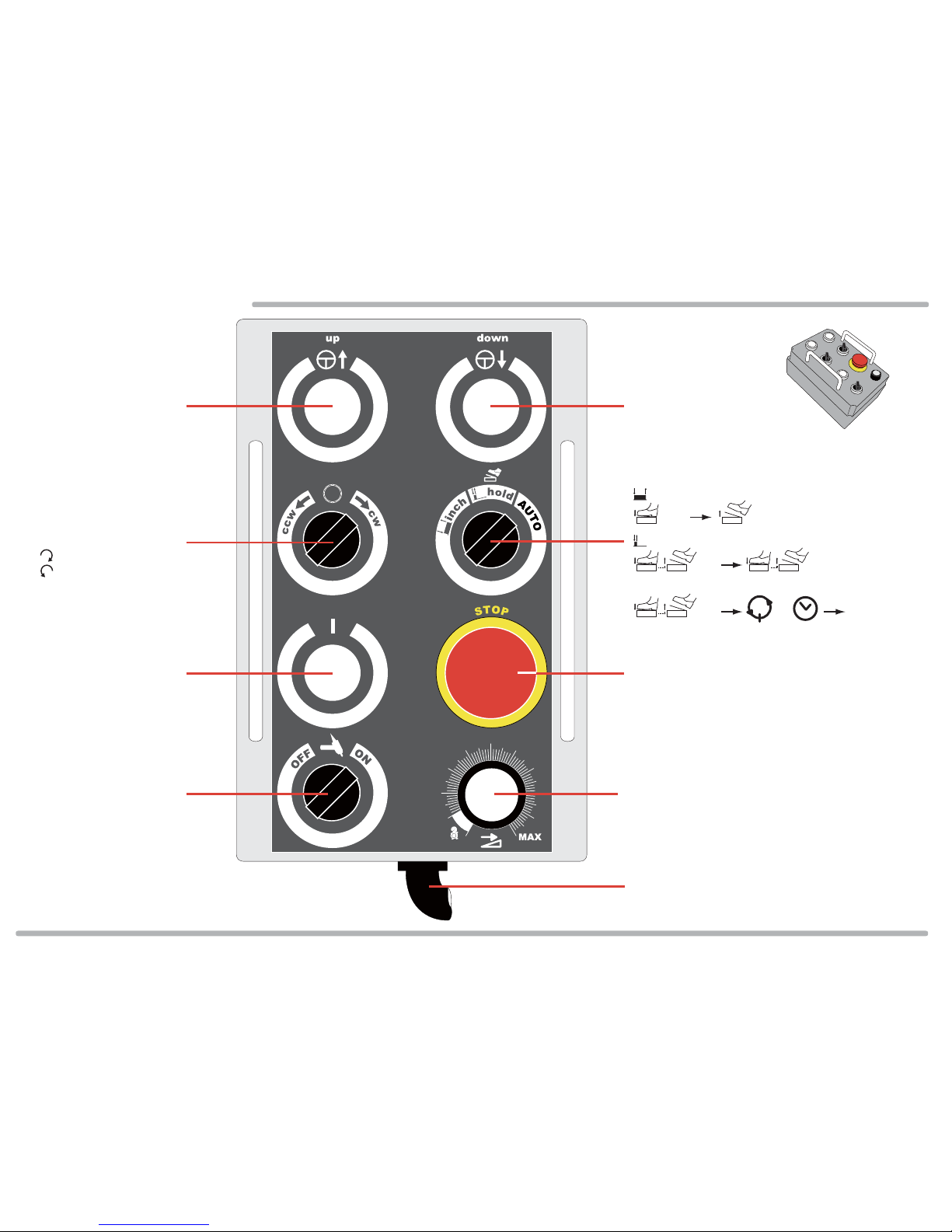
Contril Panel
2.8 Page 10
Standard
Set
AUTO MODE
EVPA01
Crater
Overlap2 Cycle
Time4 Cycle
Power switch Power lamp
Welder start socket
Pedel switch socket
Rrmote contril line
Power line.
O-OFF
I-ON
Add time
+0.1 sec
UNIT:0.1 sec
00.0 ~ 99.9 sec
Minus time
-0.1 sec
Overlap set
Timer set
Overlap set
Timer set
Arc way of the welder
Start welding arc time set
Start welding arc time set
Crater welding arc time set
Crater welding arc time set
Select set
Figure:2.8-1
Timer set UNIT:1 sec
Contril Panel
2.9 Page 11
Table Rotation Speed
1
0
2
0
3
0
4
0
5
0
6
0
7
0
8
0
9
0
Weld in step switch
O-OFF
I-ON
Table Rotation Start Button Stop button
Table Roation Direction Switch
-cw:Clockwise
-ccw:counterclockwise
-inch
-Start -Stop
-hold
-Start
-Start
-Stop
-Stop
AUTO
Overlap Time
or
Table Roation Start Method
Remote Contril Line
Figure:2.9-1
Table Angle Down ButtonTable Angle Up Button

Chapter 3: Machine Installation
General
3.1
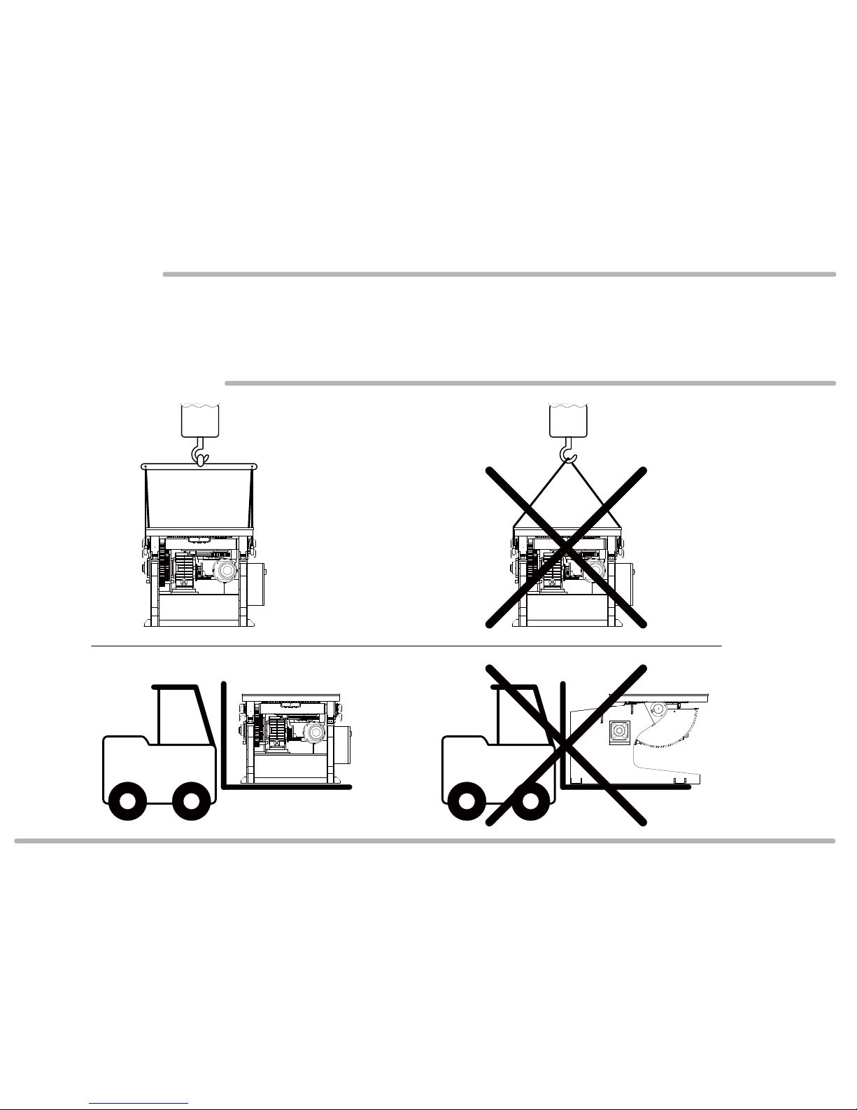
Transporting
3.2
3.1.1 In order to guarantee the security that the work piece moves, so need really installation POS for MC18 series positioner, can operate after confirming installing finishing, please scrutinize the
explanation of this chapter and do it.
5 Ton 5 Ton
Figure:3.2-3 Figure:3.2-4
5 Ton 5 Ton
Figure:3.2-1 Figure:3.2-2
Page 12
Page 13
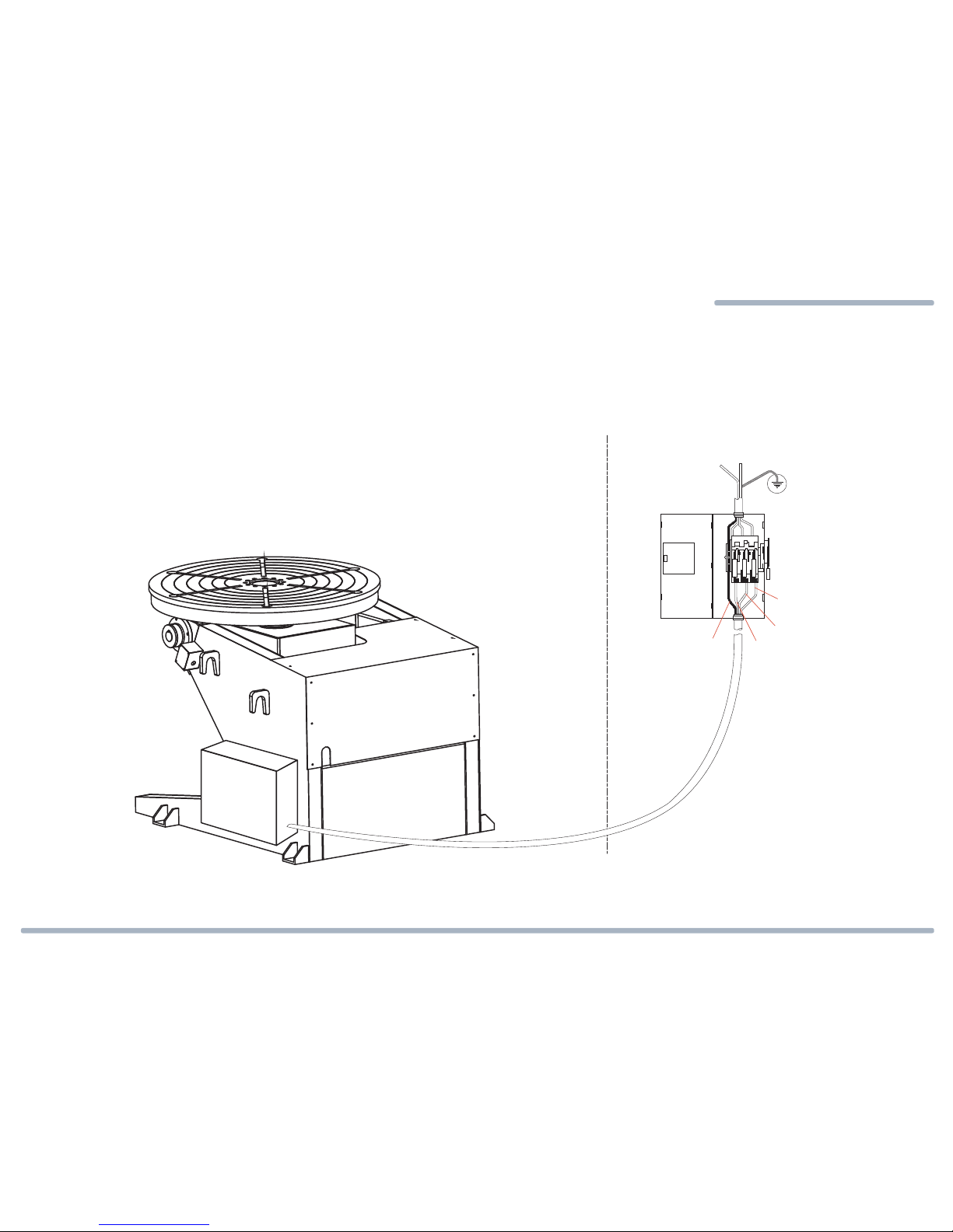
Electrical Supply Requirements and Connection
V1:AC 220V / 20A / 50;60Hz / 3Ø
V2:AC 380V / 18A / 50Hz / 3Ø
V1:AC 220V / 20A / 50;60Hz / 3Ø
V2:AC 380V / 18A / 50Hz / 3Ø
3.2
3.2.1 The power is and has earth circuit.
3.2.2 Use the power broken circuit switch ( Electric current 5A ).
3.2.3 Use the proper tool and really lock the power cable and power broken circuit switch.
3.2.4 There can't be damage on the power cable surface or join after the electric wire ruptures.
3.2.5 Do not propose joining the power switch with welde machine.
USER SIDE
L1
L2
L3
PE
Figure:3.2-1
1 2
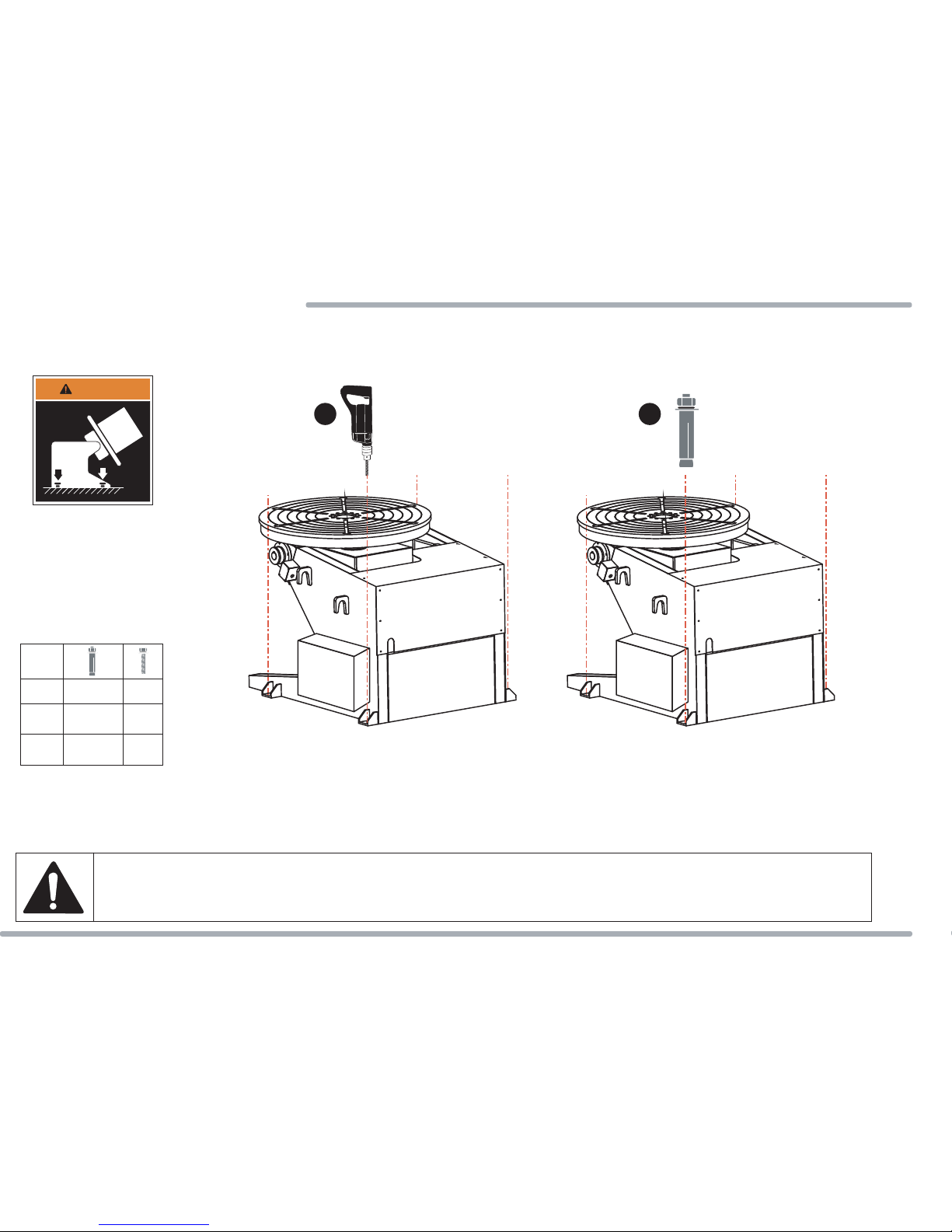
Figure:3.3-3 Figure:3.3-4
Regular Machinery
ATTENTION
3.3
3.3.1 If machinery was fixed and installation in the ground , use the ground bolt [Figure:3.3-2] to lock machinery on the ground.
Figure:3.3-1
Figure:3.3-2
If machinery was fixed and installation in the strong steel foundation, please drilling four screw holes on the strong steel foundation and use the screw [Figure:3.3-2]
to lockmachinery on the strong steel foundation.
Page 14
300MCA
500MCA
750MCA
M12x40mm
M12x40mm
M12x40mm
M14
M14
M14

TO
Welding machine
Figure:3.4-1
Page 15
Welder Cooperates
3.4.1 Please lock the cable ,welder contact and carbon brush firmly.

Chapter 4: Machine's Operation
Table of contents


