3
3
1 QUICKSTART .....................................................................................................5
1.1 Definition of term “device” .............................................................. 5
2 SYMBOLS ............................................................................................................5
3 INTENDED USE ................................................................................................6
3.1 Restrictions ........................................................................................ 6
4 BASIC SAFETY INSTRUCTIONS .............................................................6
5 GENERAL INFORMATION ...........................................................................7
5.1 Scope of supply................................................................................7
5.2 Contact address ...............................................................................7
5.3 Warranty ............................................................................................. 7
5.4 Information on the internet .............................................................7
6 DESCRIPTION OF SYSTEM .......................................................................8
6.1 General description .........................................................................8
6.2 Designs ............................................................................................... 8
6.3 Structure of the device ...................................................................9
7 TECHNICAL DATA ...........................................................................................9
7.1 Conformity .........................................................................................9
7.2 Standards ........................................................................................... 9
7.3 Operating conditions .......................................................................9
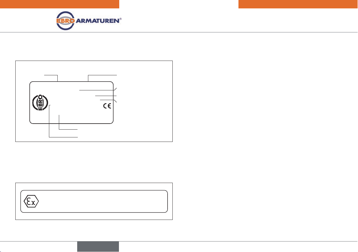
7.4 Type labels .......................................................................................10
7.5 Mechanical data .............................................................................10
7.6 Electrical data..................................................................................10
7.7 Pneumatic data ...............................................................................11
8 OPERATION .....................................................................................................12
8.1 Description of the operating and display elements ................12
8.2 Function of the keys .......................................................................13
9 OPERATING STATES .................................................................................. 14
9.1 Changing the operating state ......................................................14
9.2 Displays in AUTOMATIC mode .................................................... 14
9.3 Master code.....................................................................................15
10 OPERATING LEVELS .................................................................................. 16
10.1 Switching between the operating levels .................................16
11 ATTACHMENT AND ASSEMBLY ............................................................. 16
11.1 Installation of devices for the hazardous area .......................16
11.2 Attachment to a proportional valve with rotary actuator .....16
12 EXTERNAL PATH SENSOR .................................................................... 18
12.1 Connection of external position sensors
for type EP 501 L .........................................................................19
13 PNEUMATIC CONNECTION ....................................................................19
13.1 Safety end positions ....................................................................20
14 ELECTRICAL INSTALLATION ..................................................................22
14.1 Safety instructions ......................................................................22
14.2 Electrical installation with cable gland ....................................22
14.3 Terminal assignment for cable gland -
positioner Type EP 501 ..............................................................23
14.4 Terminal assignment for cable gland -
process controller Type EP 501 C ..........................................24
14.5 Terminal assignment for cable gland –
Typ EP 501 L ................................................................................25
Contents
english
Type EP 501
english