STI IMI FasTrak Compact FTC-I User manual

Smart Positioner Series FTC-I
FasTrak Compact
SAFETY MANUAL 9031
INSTRUCTIONS - INSTALLATION, USE AND MAINTENANCE
ADDITIONAL INSTRUCTIONS 4049(Ex)/IST

____________________________________________________________________________________
STI S.r.l. – Via Dei Caravaggi 15, 24040 Levate (BG) – ITALY www.imi-critical.com
Manual 9031, rev. 02 27/02/2018 – FTC
i
27/02/2019 02 Changed label N. Zenoni A. Negri
28/09/2018 01 Issue N. Zenoni A. Negri
Date Revision Description Compiled Approved
STI S.r.l has taken every care in collecting and verifying the documentation contained in this Instruction
Manual. The information herein contained are reserved property of STI S.r.l.

____________________________________________________________________________________
STI S.r.l. – Via Dei Caravaggi 15, 24040 Levate (BG) – ITALY www.imi-critical.com
Manual 9031, rev. 02 27/02/2018 – FTC
ii
INDEX
1 SAFETY INSTRUCTIONS .................................................................................................................... 1
2 RATED CHARACTERISTICS ............................................................................................................... 3
3 COMMISSIONING................................................................................................................................. 5
4 MAINTENANCE .................................................................................................................................... 6

____________________________________________________________________________________
STI S.r.l. – Via Dei Caravaggi 15, 24040 Levate (BG) – ITALY www.imi-critical.com
Manual 9031, rev. 02 27/02/2018 – FTC
iii

_____________________________________________________________________________________
STI S.r.l. – Via Dei Caravaggi 15, 24040 Levate (BG) – ITALY www.imi-critical.com
Manual 9031, rev. 02 27/02/2018 – FTC
- 1
-
1 SAFETY INSTRUCTIONS
Important
To be read, and understood, in conjunction with the FTC – FasTrak Compact
Instruction Manual 4049.
Directive 2014/34/EU (ATEX) IECEx Scheme
II 2G Ex ia IIC T5/T4 Gb Ex ia IIC T5/T4 Gb
CENELEC Standards IEC Standards
EN 60079-0: 2012+A11: 2013 60079-0: 2017
EN 60079-11: 2012 60079-11: 2011
Figure 1 – example of label
Positioners series FTC-Ixxxxxx are designed to “pilot” and control the position of a valve on which they are
mounted; they receive an “intrinsically safe” analogue input signal 4-20 mA (SETPOINT), which is also an
info about the required position of the valve. Then, it controls the position of the valve through an internal
sensor (potentiometer connected to a rotating shaft): the result is elaborated by the μP, which activates an
I/P converter, to modulate air or nitrogen [or, in specific conditions, natural gas (CH4)] sent to the chamber(s)
connected to the actuator.
As an additional (optional) function, the FTC-Ixxxxxx may modulate a passive 4-20 mA analogue signal
(FEEDBACK), to indicate the current position of the valve. From the Intrinsic Safety point of view, the 2
circuits are totally independent.
Configuration and diagnostic of the device is possible by the integrated local interface (display & keyboard)
or using the HART capability. Additionally, it is possible to have the benefit of high speed connection using
the ‘FTx positioner connection cable’ on port X4.
Warning
X4 connection facilities is restricted to use in a non-hazardous area following the
below 2 indication:
- Only the ‘FTx positioner connection cable’ can be used.
0477

_____________________________________________________________________________________
STI S.r.l. – Via Dei Caravaggi 15, 24040 Levate (BG) – ITALY www.imi-critical.com
Manual 9031, rev. 02 27/02/2018 – FTC
- 2
-
- The laptop used must be powered from battery or by a power supply unit in
compliance with IEC 60950-1 with Maximum Output Voltage (Um) ≤ 30V.
Warning
In case of “minimum ambient temperature” below -40°C, the optional FEEDBACK
cannot be connected and the jumpers on the PCB FTCompact-PW, for internal
circuit connection, must be removed by the User.
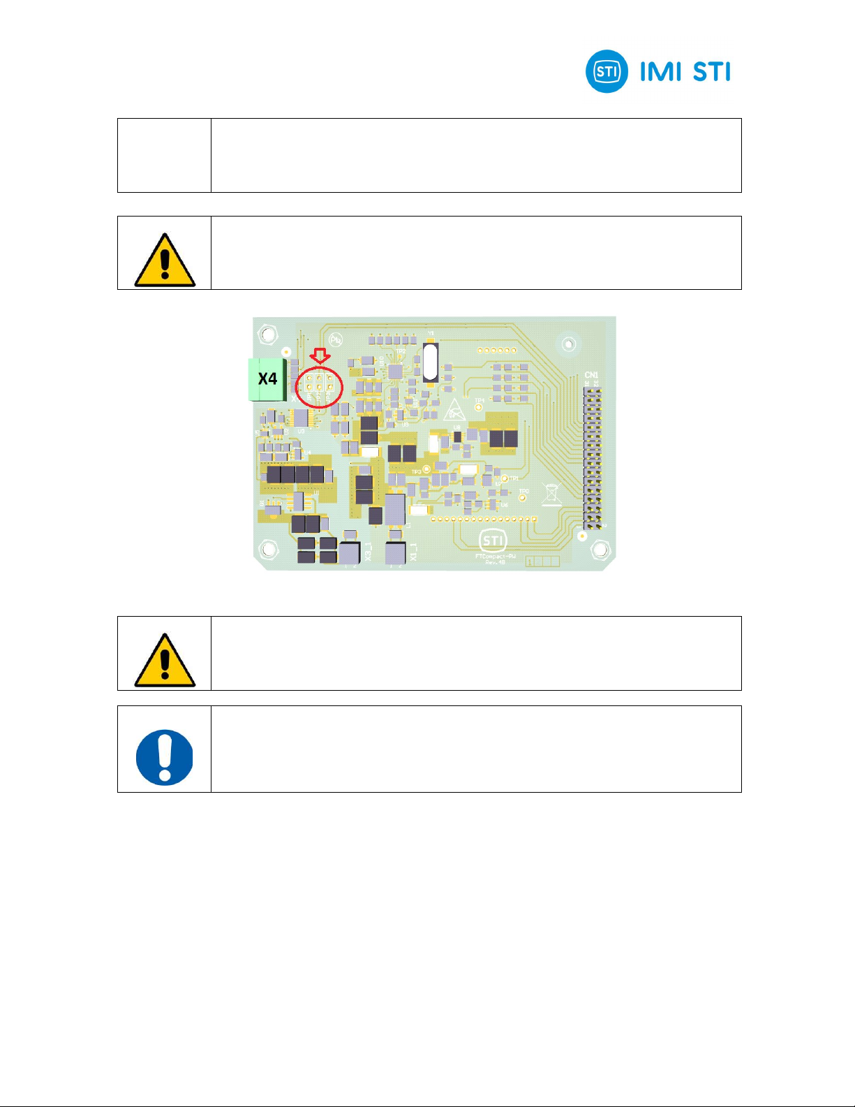
Figure 2 – FTC-I electric circuit
Warning
Highlighted in the red circle are the jumpers (JP1, JP2 and JP3) that must be
removed to exclude the feedback circuit when the minimum temperature can be
below -40°C.
Important
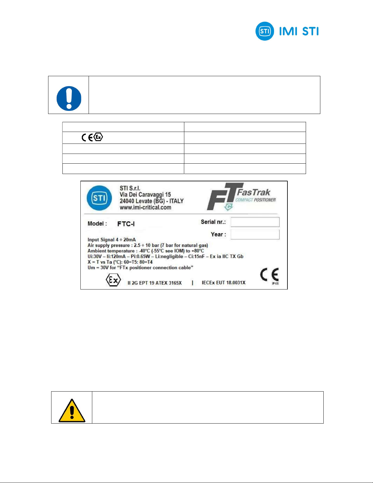
Positioners series FTC-Ixxxxxx are designed and certified in conformity to the
European Directive 2014/34/EU, and according to the International IECEx Scheme.
The Positioners shall be connected to 1 or 2 [Ex ia] or [Ex ib] Associated Apparatus (Diode Safety Barrier or
Galvanic Isolator), in compliance with the maximum voltage (Ui), current (Ii) and power (Pi) values stated in
the label (see "Rated characteristics"). In both cases the Positioner can be installed in Zone 1 (or Zone 2),
but when the whole system has "ib" protection level, the Positioner shall not be used to modulate natural gas
(CH4). In case the system has "ic" protection level, the Positioner may be installed only in Zone 2 and, of
course, it cannot be used to modulate natural gas (CH4).
The Positioner shall be installed in compliance with EN IEC 60079-14 Standard (current Issue) and any
inspection maintenance shall be carried out following the provisions of EN IEC 60079-17 Standard (current
Issue); all Intrinsically Safe circuits shall be included in Descriptive System Documents (EN IEC 60079-14,
art. 4.2 and EN IEC 60079-25, art. 4).

_____________________________________________________________________________________
STI S.r.l. – Via Dei Caravaggi 15, 24040 Levate (BG) – ITALY www.imi-critical.com
Manual 9031, rev. 02 27/02/2018 – FTC
- 3
-
2 RATED CHARACTERISTICS
Rated Characteristics
Input signal
Air supply pressure
Type of protection
ATEX Code
4 ÷ 20 mA
2.5 ÷ 10 bar (7 bar max. when Methane is used)
Ex ia IIC TX (*) Gb
II 2G
Safety Parameters (identical for both channels)
Ui (maximum voltage)
Ii (maximum current)
Pi (maximum power)
Li (internal inductance)
Ci ((internal capacitance)
Ambient temperature (Ta)
30 Vdc
120 mA
650 mW
Negligible
15 nF
-55°C to +80°C (but limited to -40°C minimum when FEEDBACK circuit is
connected)
(*) X = Temperature Class vs. Tamax : 60°C = T5 ; 80°C = T4
Figure 3 – FTC-I Smart Positioner

_____________________________________________________________________________________
STI S.r.l. – Via Dei Caravaggi 15, 24040 Levate (BG) – ITALY www.imi-critical.com
Manual 9031, rev. 02 27/02/2018 – FTC
- 4
-
Figure 4 – FTC-I Terminal Board XT1
L+ & L
-
Power connection (from Associated Apparatus)
AO+ & AO
-
Optional Analogue Output (to Associated Apparatus)
Central
terminal
Earth / Ground

_____________________________________________________________________________________
STI S.r.l. – Via Dei Caravaggi 15, 24040 Levate (BG) – ITALY www.imi-critical.com
Manual 9031, rev. 02 27/02/2018 – FTC
- 5
-
3 COMMISSIONING
1. Before commissioning a safe electrical equipment, in a system or plant, the user shall check its
compliance with the design data and its correct installation. An Initial Inspection shall be carried out
by suitably qualified personnel, according to the requirements of the Standard EN IEC 60079-17
(current Issue).
2. Verify that any special conditions for safe use, detailed on the EU Type Examination Certificate or
on the IECEx Certificate of Conformity, are complied with, paying special attention to the installation
conditions, if any.
3. Check that the Positioner supplied is suitable for the specific hazardous area classification (Zone 1
or Zone 2, gas group IIA, IIB, or IIC, according to the System Protection Level).
Warning
The Device is NOT suitable neither for zone 0 nor for Locations with Combustible
Dusts.
4. Verify that the temperature class, marked on the Positioner, is correct for the area classification,
according to the actual ambient temperature.
5. Check that the Positioner is connected to the Associated Apparatus (1 per channel) provided for in
the corresponding Descriptive System Document.

_____________________________________________________________________________________
STI S.r.l. – Via Dei Caravaggi 15, 24040 Levate (BG) – ITALY www.imi-critical.com
Manual 9031, rev. 02 27/02/2018 – FTC
- 6
-
4 MAINTENANCE
Warning
The following instructions must be respected:
1. Maintenance shall be carried out by suitably qualified personnel only, trained in
the specific features of the equipment, and on the Intrinsic Safety technique, in
compliance with the provisions of the Standard EN IEC 60079-19 (current Issue).
The replacement of any part of the Positioner series FTC-I shall be done only
with original parts supplied by STI S.r.l.
2. Periodic Inspections shall be carried out, by suitably qualified personnel, in
compliance with the provisions of the Standard EN IEC 60079-17 (current Issue).
3. The replacement of any part of the Positioner series FTC-I shall be done with
original parts supplied by STI S.r.l.
4. The use of Positioners that have undergone work not authorized by STI S.r.l.
absolves
STI S.r.l.
from all liability and invalidates the relative warranty.

_____________________________________________________________________________________
STI S.r.l. – Via Dei Caravaggi 15, 24040 Levate (BG) – ITALY www.imi-critical.com
Manual 9031, rev. 02 27/02/2018 – FTC - 7
-

IMI STI - Headquarters
Via Dei Caravaggi 15
24040 Levate (BG)
Italy
Tel. +39 035 2928.2
Fax +39 035 2928.247
IMI Critical Engineering
Lakeside, Solihull Parkway
Birmingham Business Park
Birmingham B37 7XZ
United Kingdom
Tel. +44 (0)121 717 3700
Fax +44 (0)121 717 3701
www.imi-critical.com
imisti.sale[email protected]
Table of contents
Other STI Valve Positioner manuals