SKF LTS Product manual

LTS profile rail slides from SKF
Installation and maintenance guide

Contents
1General ................................... 3
2Safety .................................... 4
2.1 Used symbols ............................... 4
2.2 Hazard potential of profile rail slides .............. 5
2.3 Designateduse ............................. 5
2.4 Authorized personnel ......................... 6
2.5 General safety advise ......................... 6
2.6 Transport and interim storage . . . . . . . . . . . . . . . . . . 8
2.7 Electricalsafety ............................. 9
2.8 Exclusion of liability . . . . . . . . . . . . . . . . . . . . . . . . . . 9
3Accuracies ................................. 10
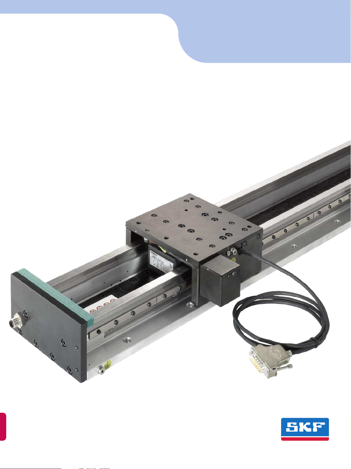
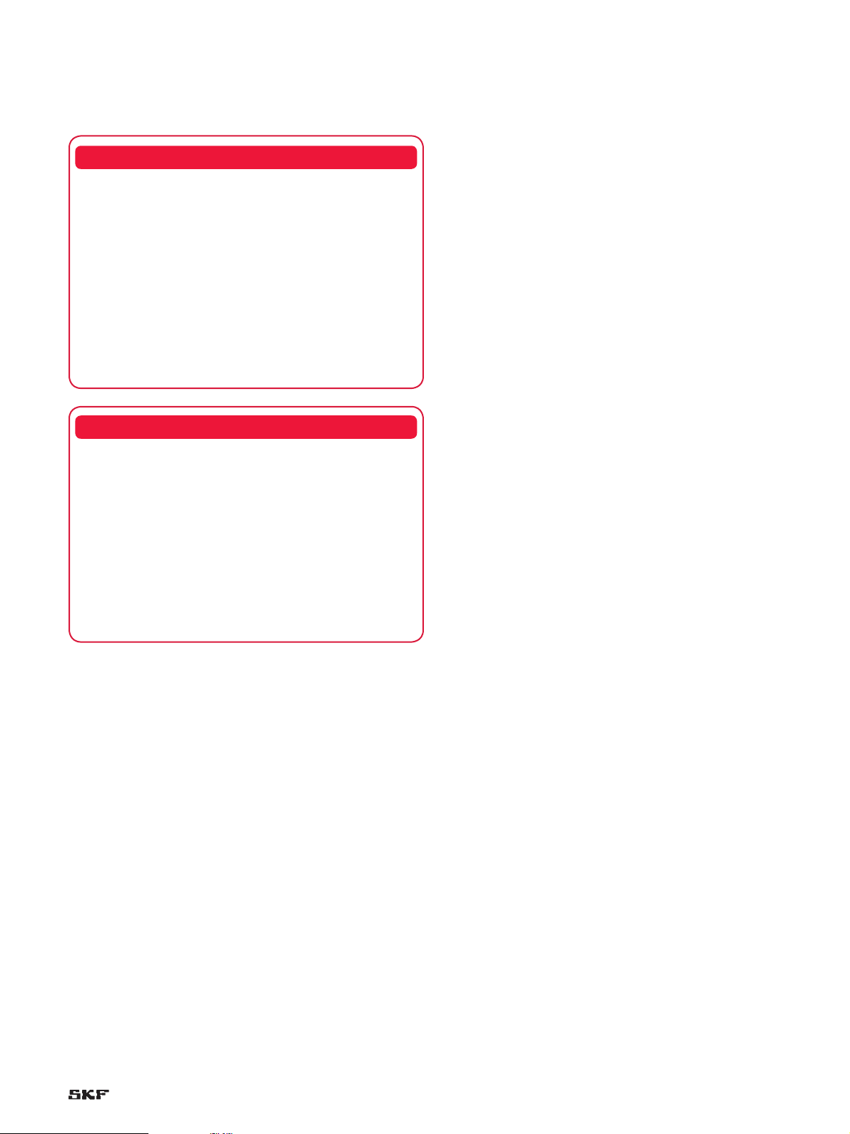
4Product description . . . . . . . . . . . . . . . . . . . . . . . . . . 11
4.1 Design (exploded drawing) ..................... 11
4.2 Dimension tables ............................ 12
4.3 Load carrying capacity of slide tops . . . . . . . . . . . . . . 15
5Technical data .............................. 16
5.1 Motor ..................................... 16
5.2 DC link voltage 515 V DC . . . . . . . . . . . . . . . . . . . . . . 18
5.3 DC link voltage 600 V DC . . . . . . . . . . . . . . . . . . . . . . 21
5.4 Motor temperature sensor ..................... 24
5.5 Linear encoder .............................. 25
5.6 Limitswitches .............................. 26
6Accessories ................................ 27
6.1 Bellows ................................... 27
6.2 Energy chain with mounting bracket . . . . . . . . . . . . . 27
6.3 Cables .................................... 29
7Mounting instructions according to
directive 2006/42/EC, appendix VI ................ 30
7.1 Mechanical interfaces ......................... 30
7.2 Electrical interfaces . . . . . . . . . . . . . . . . . . . . . . . . . . 33
7.2.1 Pin configuration . . . . . . . . . . . . . . . . . . . . . . . . 33
7.2.2 Connection of protective conductors.......... 34
7.3 Start up ................................... 35
7.3.1 Preconditions ........................... 35
7.3.2 Commissioning with a servo amplifier . . . . . . . . 35
8Maintenance and repairs . . . . . . . . . . . . . . . . . . . . . . 36
8.1 Preventive maintenance ....................... 36
8.2 Lubrication ................................. 36
8.3 Relubrication................................ 37
8.4 Cleaning the measuring scale ................... 37
8.5 Repairs .................................... 37
9Ordercode ................................ 38
10 Declaration of incorporation .................... 39
The SKF brand now stands for more
than ever before, and means more
to you as a valued customer.
While SKF maintains its leadership as a
high-quality bearing manufacturer
throughout the world, new dimensions
in technical advances, product support
and services have evolved SKF into a
truly solutions-oriented supplier,
creating greater value for customers.
These solutions enable customers to
improve productivity, not only with
breakthrough application-specific prod-
ucts, but also through leading-edge
design simulation tools and consultancy
services, plant asset efficiency mainte-
nance programmes, and the industry’s
most advanced supply management
techniques.
The SKF brand still stands for the very
best in rolling bearings, but it now
stands for much more.
SKF – the knowledge engineering
company
2

Due to the high and steadily increasing requirements on linear axes,
the conventional drive systems like spindle, gear rack and toothed
belt are quickly meeting their limitations.
In particular the demand for high speeds, accelerations and
accuracies, combined with a simultaneous increase in availability,
can only be met with linear direct drive technology.
Direct drive systems in combination with high-resolution linear
encoders offer considerably higher rigidity due to the elimination
of mechanical drive and coupling elements. This can be seen in
the higher mechanical natural frequency and has positive effects
on the achievable control quality and dynamics.
The new SKF profile rail slides of series LTS offer all these advan-
tages. The LTS axes are driven by newly developed, air-cooled
Siemens linear motors.
Advantages of the LTS series:
Direct power transmission without mechanical coupling elements•
High speeds•
High accelerations•
High positioning accuracy•
Short settling times•
Nearly maintenance free•
Clearance-free drive•
High static and dynamic load rigidity•
High control quality•
High availability•
Due to the features listed above, LTS profile rail slides can be used in
nearly all industrial sectors. The main fields of application include:
Productronics (equipping and inspecting of PCBs, bonding, …)•
Laser industry (laser cutting, rapid prototyping, measuring, …)•
Automation technology (pick & place, …)•
Optics (measuring and grinding of lenses, …)•
General1
3

These operating instructions contain basic guidelines that have to be
observed during mounting, operation and maintenance of the pro-
file rail slide LTS. It is imperative that these instructions, particularly
the “Safety” section, be thoroughly studied and understood by the
fitter and any skilled workers or operators prior to mounting and
start-up.
If there is any uncertainty or doubt, please contact SKF for support.
These operating instructions or the manual for the overall system,
which contains the most important elements of these operating
instructions, must always be available at the place of operation of
the slides or the system.
It is not only the general safety advice listed here under “Safety”
which must be observed. Pay also attention to the additional safety
advice in the other chapters of this manual and to existing national
accident prevention regulations.
Used symbols2.1
Danger
Signalize a dangerous situation, which can lead to death or severe
personal injury, if the precautionary measures are ignored.
Warning
Signalize
a dangerous situation, which can lead to severe or light
personal injury, if the precautionary measures are ignored.
Caution
Signalize a dangerous situation, which can lead to light personal injury
or property damage, if the precautionary measures are ignored.
Safety2
Warning text
tT!DANGER
Warning text
tT!WARNING
Warning text
tT!CAUTION
4

Hazard potential of profile rail2.2
slides
These dangers must be prevented through suitable protective
devices at the final machine. There are warning labels
on both end
plates if the profile rail slide has bellows and on two outer magnets
if there are no bellows. It is forbidden
to remove or damage these
labels. If you need new warning labels, please contact SKF.
Designated use2.3
LTS profile rail slides must only be used for positioning loads that•
do not give off emissions which could pose a danger to the axis
and that do not overload the axis. The transport of people and
animals is forbidden.
LTS profile rail slides have been designed for horizontal installa-•
tion as a single axis or as a combination of axes such as cross
tables or gantries. Where vertical installation is planned, please
contact SKF.
LTS profile rail slides must not be used in outdoor, wet or explo-•
sive areas.
LTS profile rail slides have to be used within the temperature•
range of 0 to 55 °C.
LTS profile rail slides have been designed and constructed in
compliance with state-of-the-art technology. They are safe to
use under the conditions tested by us. Nevertheless, they can
pose potential hazard to the life and health of the operators as
well as to the machine and other asset values and to efficient
machine operation if:
they are not mounted or operated by trained or at least•
instructed personnel.
they are used incorrectly or for a purpose other than intended.•
the safety advice in the system manual is not observed.•tT!DANGER
These in particular are the risks:
There is a risk of trapping, slicing or cutting fingers or the•
hand between the slide top and the end plates. During con-
tinuous operation, the motor and thus the slide top can heat
up strongly, which holds the danger of burning when touching
the parts.
Further sources of danger are the strong attractive forces of•
the permanent magnets fitted in the secondary part, the
resulting magnetic field and the risk of electric shocks when
touching the motor contacts.
tT!DANGER
5

Authorized personnel2.4
LTS profile rail slides must only be installed, started up, operated
and maintained by qualified personnel.
The operator of LTS profile rail slides must ensure that these
operating instructions are available to the workers in
charge of
installation, start-up, operation and maintenance of the slides, and
make sure that the manual is thoroughly
studied and understood.
Only then may the machine be put into operation.
General safety advice2.5
It is imperative that the following notices are observed during
installation, start-up, maintenance, operation and repair!
Any installation and repair work to LTS profile rail slides should•
only ever be carried out when the machine is at a standstill
and de-energized. Prior to begin of the work it must be ensured
that the intermediate circuit of the power output module is
completely discharged and that unauthorized or unintended
switching on of supply voltage by third party is not possible.
According to 2006/42/EC machine directive of 17 May 2006,•
an LTS profile rail slide is a partly completed machine. Opera-
tion of the axis is only permissible with suitable mechanical
and electrical protective devices. These must comply with the
laws and regulations of the respective country in which the
profile rail slide is operated.
LTS profile rail slides are fitted with strong permanent mag-•
nets. People with cardiac pacemakers or other implants that
must not be exposed to strong magnetic fields, must keep a
safety distance of at least 1,5 m. This distance must be kept
irrespective of the installation and operational condition of the
axis as well as during transport and storage. Corresponding
warning stickers are fitted directly to the axis and must also
be applied to the final machine clearly visibly by the operator
when the axis has been installed.
Magnetizable data storage media may be destroyed or dam-•
aged by the strong magnetic fields. For such data carriers
keep a minimum distance of 200 mm.
Due to the high magnetic forces of attraction, be especially•
careful during installation of the axis into the final machine as
well as during work near the axis when using iron-containing
objects (e.g. tools).
tT!DANGER
6

The standard-type motor of an LTS profile rail slide is com-•
mutated via an incremental encoder system. Depending on
the type of amplifier used, there can be a short movement
of the slide when switching on the axis. The operator must
ensure that this potential commutation movement will not
damage the machine or endanger people.
The standard version LTS profile rail slide is not fitted with a•
separate brake. In the event of voltage breakdown or failure
of the measurement system, the slide may move into its end
position uncontrolled. LTS profile rail slides are equipped with
end position dampers. If these cannot be reached because
the
application dictates limited travel, the operator must
ensure that other end position dampers are fitted to the
final machine that can take over this function in the event
of failure.
For vertical applications of the axis, please contact SKF.•
When an LTS profile rail slide without bellows is used, the•
operator is obliged to protect the magnetic rail against con-
tamination, in particular against iron-containing foreign
particles. These can destroy the motor due to the small air
gap between the primary and secondary part.
tT!DANGER
7

Transport and interim storage2.6
Avoid shocks during transport.•
Transport of the LTS profile rail slide only with original packaging.•
Always ensure that the transportation safety device is mounted•
(† fig. 1).
Storage only in dry, well-tempered areas.•
Remove packaging just before mounting the LTS and dispose it•
correctly.
The profile rail slide LTS must only be lifted at the bottom part.•
Caution! When lifting a lprofile rail guide slide always support the•
whole bottom part of it. Otherwise a deflection can occur due to
it’s own weight resulting in reduced accuracy.
Longer LTS profile rail slides (•† table 1) are delivered with four
M8 threads in the bottom part to screw in four eyebolts for lifting
it († fig. 2). In case a bellow is mounted the bellow has to be
removed before making use of the eyebolts.
Only use lifters and gadgets with sufficient•load carrying capacity.
It’s only allowed to remove the transportation safety device of the•
LTS after inserting the axis into the final machine and tightening
of at least 50% of the attachment screws of the bottom part.
LTS with transportation safety device mounted
LTS with eyebolts mounted
Fig. 1
Fig. 2
Table 1
Designation Eyebolt threads available from length, mm
LTS 154… 1 000
LTS 182… 1 000
LTS 212… 760
8

Electrical safety2.7
Exclusion of liability2.8
When the safety advice is not observed this can endanger persons,
the environment and machinery. Failure to observe the safety advice
can also lead to a loss of any compensation claim.
The manufacturer assumes no liability for unauthorized modifica-
tions to the LTS, nor for improper installation, start-up, maintenance
and repairs as well as unauthorized use or improper operation of
LTS profile rail slides.
Only original replacement and expandable parts from SKF Linear
Motion and SIEMENS are approved and should be used without
exception. The use of other parts may cancel the manufacturer’s
liability for any consequences.
The LTS profile rail slide is manufactured according to protection
class 1 and protection type IP40. Both, the bottom and the top
part, are fitted with a connection for a protective earth conductor
with 2.5 mm2, see chapter 7.2.2. For proper grounding, the
protective conductor must be connected with the PE rail in the
control cabinet or
another central grounding point under low impedance. The
correct protective conductor connection must be checked ac-
cording to DIN EN 60204-1.
The plug and socket connections of motor and encoder must
never be separated or connected under voltage! Disconnecting
the motor plug is permissible only after switching off the power
output module of the servo amplifier and discharging of the in-
termediate circuit down to below 40 V. The time for discharging
of the intermediate circuit depends
on the servo amplifier used
and the connected load and can be gathered from the relevant
documentation. As a rule, a discharging period of 5 minutes can
be considered sufficient.
tT!DANGER
9

Accuracies3
The overall precision with which an object can be positioned in space
depends on different factors. Looking at a profile
rile slide these
characteristics are:
Straightness of the slide movement, vertically and horizontally•
Rotation of the slide movement through pitch and yaw angle•
Positioning accuracy of the individual axes with following•
parameters:
Resolution and accuracy class of encoder–
Repeatability–
Perpendicularity of the individual axes relative to each other•
Temperature difference•
The straightness, rotation and perpendicularity of a slide are greatly
influenced by the mechanical stability and stiffness of the guides and
the slide components. In combination with stable, high-precision
slide parts and preloaded profile rail guides these values of the pro-
file rail slide LTS are extremely precise.
The positioning accuracy of a slide is positively influenced by the
use of high-precision linear encoders on one hand and high-quality
servodrives on the other.
In a multi-axis unit consisting of profile rail slides, the accuracies
of the individual slides add up either positively or negatively. Addi-
tionally there can be elastic deformations of partly supported axes.
Diagram 1
P5
150
100
50
0
100 300 500 700 900 1 100 1 300 1 500 1 700 1 900 2 100 2 300 2 500
P2
Straightness (µm)
Stroke (mm)
Information on the probable accuracies of a particular multi-axis
unit, including under load, can be obtained on request.
All accuracy data in this manual apply to an unloaded, individual
slide of standard quality P5, which is fastened with
all of its attach-
ment screws to a absolutely flat surface (flatness 3 µm/300 mm),
measured at room temperature. The values for straightness and
rotation are measured similar to VDI2617, sheet 3.
10

Design4.1
LTS profile rail slides with linear motor consist of the following com-
ponents, schematically illustrated in the drawing below:
Product description4
Bellows
Mounting bracket for energy chain
Bellow fixation
Slide top
Rear side panel
Transportation safety device
Limit switch cam
Motor primary part
Magnets secondary part
Limit switch strip
Limit switch
Limit switch
connector
Buffer
End plate
Bottom part
Retaining strip
Profile rail guide
Measuring scale
Measuring head
Measuring head support
Carriage
Connector angle plate
Connector hood
Front side panel
End plate
11

Dimension tables4.2
Table 1
LTS 154.L1.1FN3-050-xK: Slides with linear motor drive, with or without bellows
LTS154.L1.1FN3-050-1K LTS154.L1.1FN3-050-2K
Stroke1) Stroke1)
L1 n GU2) L2 L5 L6 S1 S2 GO3) L2 L5 S1 S2 GO3)
mm – kg mm mm kg mm kg
280 1 4,5 142 118 22,5 77 98 2,7 247 127 – – 4,6
400 2 6,2 142 118 22,5 166 218 2,7 247 127 86 113 4,6
520 3 7,9 142 118 22,5 256 338 2,7 247 127 175 233 4,6
640 4 9,5 142 118 22,5 345 458 2,7 247 127 264 353 4,6
760 5 11,2 142 118 22,5 434 578 2,7 247 127 354 473 4,6
880 6 12,8 142 118 22,5 524 698 2,7 247 127 443 593 4,6
1 000 7 14,5 142 118 22,5 613 818 2,7 247 127 533 713 4,6
1 120 8 16,1 142 118 22,5 703 938 2,7 247 127 622 833 4,6
1 240 9 17,8 142 118 22,5 792 1 058 2,7 247 127 711 935 4,6
1 360 10 19,4 142 118 22,5 881 1 178 2,7 247 127 801 1 073 4,6
1 480 11 21,0 142 118 22,5 971 1 298 2,7 247 127 890 1 193 4,6
1 600 12 22,6 142 118 22,5 1 060 1 418 2,7 247 127 980 1 313 4,6
1 720 13 24,3 142 118 22,5 1 150 1 538 2,7 247 127 1 075 1 433 4,6
1 840 14 25,9 142 118 22,5 1 239 1 658 2,7 247 127 1 165 1 553 4,6
1 960 15 27,5 142 118 22,5 1 328 1 778 2,7 247 127 1 254 1 673 4,6
Ø6,6/ Ø11x6,8
ca. 100
80
n x 120
80
10L1
L614
L5
6060
81
15444
28
L2
M6x10
(6x)
3
Fahrtrichtung
10
127
120
1) Operating stroke – S1 with bellows, S2 without bellows
2) GU = Stationary mass of slide bottom
3) GO = Linear moving mass of slide top
The operating stroke is defined as the maximum stroke between the limit switches
Distance limit switch – end plate: 20 mm (LTS without bellows)
Distance limit switch – end buffer: 7,5 mm (LTS without bellows)
Distance limit switch – block length bellows: 10 mm (LTS with bellows)
12

Table 2
LTS182.L1.1FN3-100-xK: Slides with linear motor drive, with or without bellows
LTS182.L1.1FN3-100-1K LTS182.L1.1FN3-100-2K LTS182.L1.1FN3-100-3K
Stroke1) Stroke1) Stroke1)
L1 n GU2) L2 L5 L6 S1 S2 GO3) L2 L5 L7 S1 S2 GO3) L2 L5 L7 S1 S2
GO
3)
mm – kg mm mm kg mm mm kg mm mm kg
280 1 5,5 142 118 22,5 77 98 3,7 247 127 155 – – 6,1 352 127 155 – – 8,5
400 2 7,6 142 118 22,5 166 218 3,7 247 127 155 86 113 6,1 352 127 155 – – 8,5
520 3 9,7 142 118 22,5 256 338 3,7 247 127 155 175 233 6,1 352 127 155 101 128 8,5
640 4 11,8 142 118 22,5 345 458 3,7 247 127 155 264 353 6,1 352 127 155 190 248 8,5
760 5 13,8 142 118 22,5 434 578 3,7 247 127 155 354 473 6,1 352 127 155 279 368 8,5
880 6 15,9 142 118 22,5 524 698 3,7 247 127 155 443 593 6,1 352 127 155 369 488 8,5
1 000 7 17,9 142 118 22,5 613 818 3,7 247 127 155 533 713 6,1 352 127 155 458 608 8,5
1 120 8 20,0 142 118 22,5 703 938 3,7 247 127 155 622 833 6,1 352 127 155 548 728 8,5
1 240 9 22,0 142 118 22,5 792 1 058 3,7 247 127 155 711 935 6,1 352 127 155 637 848 8,5
1 360 10 24,1 142 118 22,5 881 1 178 3,7 247 127 155 801 1 073 6,1 352 127 155 726 968 8,5
1 480 11 26,1 142 118 22,5 971 1 298 3,7 247 127 155 890 1 193 6,1 352 127 155 816 1 088 8,5
1 600 12 28,2 142 118 22,5 1 060 1 418 3,7 247 127 155 980 1 313 6,1 352 127 155 905 1 208 8,5
1 720 13 30,2 142 118 22,5 1 150 1 538 3,7 247 127 155 1 075 1 433 6,1 352 127 155 995 1 328 8,5
1 840 14 32,2 142 118 22,5 1 239 1 658 3,7 247 127 155 1 165 1 553 6,1 352 127 155 1 084 1 448 8,5
1 960 15 34,3 142 118 22,5 1 328 1 778 3,7 247 127 155 1 254 1 673 6,1 352 127 155 1 173 1 568 8,5
1) Operating stroke – S1 with bellows, S2 without bellows
2) GU = Stationary mass of slide bottom
3) GO = Linear moving mass of slide top
The operating stroke is defined as the maximum stroke between the limit switches
Distance limit switch – end plate: 20 mm (LTS without bellows)
Distance limit switch – end buffer: 7,5 mm (LTS without bellows)
Distance limit switch – block length bellows: 10 mm (LTS with bellows)
L5
L7
6060
ca. 100
80
n x 120
80
10 L1 10
L2
L614
18244 3
81
28
Ø6,6/ Ø11x6,8
M6x10
(6x) M6x10
(6x)
Fahrtrichtung
120
155
13

1) Operating stroke – S1 with bellows, S2 without bellows
2) GU = Stationary mass of slide bottom
3) GO = Linear moving mass of slide top
The operating stroke is defined as the maximum stroke between the limit switches
Distance limit switch – end plate: 20 mm (LTS without bellows)
Distance limit switch – end buffer: 7,5 mm (LTS without bellows)
Distance limit switch – block length bellows: 10 mm (LTS with bellows)
Table 3
LTS212.L1.1FN3-150-xK: Slides with linear motor drive, with or without bellows
LTS212.L1.1FN3-150-1K LTS212.L1.1FN3-150-2K LTS212.L1.1FN3-150-3K
Stroke1) Stroke1) Stroke1)
L1 n GU2) L2 L5 L6 S1 S2 GO3) L2 L5 L7 S1 S2 GO3) L2 L5 L7 S1 S2 GO3)
mm – kg mm mm kg mm mm kg mm mm kg
280 1 7,2 142 118 22,5 77 98 4,6 247 155 185 – – 8,2 352 155 185 – – 11,9
400 2 10,1 142 118 22,5 166 218 4,6 247 155 185 86 113 8,2 352 155 185 – – 11,9
520 3 12,9 142 118 22,5 256 338 4,6 247 155 185 175 233 8,2 352 155 185 101 128 11,9
640 4 15,7 142 118 22,5 345 458 4,6 247 155 185 264 353 8,2 352 155 185 190 248 11,9
760 5 18,5 142 118 22,5 434 578 4,6 247 155 185 354 473 8,2 352 155 185 279 368 11,9
880 6 21,3 142 118 22,5 524 698 4,6 247 155 185 443 593 8,2 352 155 185 369 488 11,9
1 000 7 24,1 142 118 22,5 613 818 4,6 247 155 185 533 713 8,2 352 155 185 458 608 11,9
1 120 8 26,9 142 118 22,5 703 938 4,6 247 155 185 622 833 8,2 352 155 185 548 728 11,9
1 240 9 29,7 142 118 22,5 792 1 058 4,6 247 155 185 711 935 8,2 352 155 185 637 848 11,9
1 360 10 32,5 142 118 22,5 881 1 178 4,6 247 155 185 801 1 073 8,2 352 155 185 726 968 11,9
1 480 11 35,2 142 118 22,5 971 1 298 4,6 247 155 185 890 1 193 8,2 352 155 185 816 1 088 11,9
1 600 12 38,0 142 118 22,5 1 060 1 418 4,6 247 155 185 980 1 313 8,2 352 155 185 905 1 208 11,9
1 720 13 40,8 142 118 22,5 1 150 1 538 4,6 247 155 185 1 075 1 433 8,2 352 155 185 995 1 328 11,9
1 840 14 43,6 142 118 22,5 1 239 1 658 4,6 247 155 185 1 165 1 553 8,2 352 155 185 1 084 1 448 11,9
1 960 15 46,3 142 118 22,5 1 328 1 778 4,6 247 155 185 1 254 1 673 8,2 352 155 185 1 173 1 568 11,9
6060
L5
L7
ca. 100
80
n x 120
80
86
3
21244
30
L2
10 L1 10
L614
Ø6,6/ Ø11x6,8
M6x12
(6x) M6x12
(6x)
Fahrtrichtung
120
185
14

Load carrying capacity of slide tops4.3
Table 4
Type Precision
class
Load ratings
per carriage
Number of
carriages
Distances Maximum static load per slide1)
Cdyn Coz C D h2) Foz Foy Mox Moy Moz
– – N – mm N Nm
LTS 154.L1.1FN3-050-1K P5 5 400 8 100 4 72 96 53 31 670 16 200 1 520 1 140 1 140
LTS 154.L1.1FN3-050-2K P5 7 800 13 500 4 125 96 53 52 540 27 000 2 522 3 284 3 284
LTS 182.L1.1FN3-100-1K P5 5 400 8 100 4 72 124 53 30 940 16 200 1 918 1 114 1 114
LTS 182.L1.1FN3-100-2K P5 7 800 13 500 4 125 124 53 51 090 27 000 3 168 3 193 3 193
LTS 182.L1.1FN3-100-3K P5 10 000 20 200 4 185 124 53 76 430 40 400 4 739 7 070 7 070
LTS 212.L1.1FN3-150-1K P5 5 400 8 100 4 72 154 56,5 30 220 16 200 2 327 1 088 1 088
LTS 212.L1.1FN3-150-2K P5 10 000 20 200 4 125 154 56,5 76 430 40 400 5 885 4 777 4 777
LTS 212.L1.1FN3-150-3K P5 10 000 20 200 6 225 154 56,5 114 650 60 600 8 828 8 599 8 599
1) Loads Foz and Foy apply under central load. Moments Mox and Moz apply under pure moment load (without force). The static safety S0= Foz/Foor Foy/Fyor Mox/Mxor Moy/Myor Moz/Mzshould always be >2!
2) Distance up to the middle of the rail
C
D
h
Moy
Foz
Mox
Foy
Moz
15

Motor5.1
LTS profile rail slides are driven by iron-core, 3-phase, air cooled,
synchronous linear motor. The motor installed in a given LTS can be
seen from type designation (see chapter “Order code”). The motors
in table 1 are used.
Technical data5
Technical data
Rail slide LTS154
Motor type 1FN3-050-1K 1FN3-050-2K
Specification Symbol Unit
Boundary conditions:
DC link voltage UZK V 515 600 515 600
Maximum winding temperature TP, MAX °C 120 120 120 120
Nominal ratings
Rated force FNN 135 135 265 265
Rated current INA 2,1 2,1 3,4 3,4
Maximum velocity at rated force vMAX, FNm/s 7,0 8,2 5,5 6,5
Rated power loss PV, N W 80 80 160 160
Maximum ratings:
Maximum force FMAX N 320 320 640 640
Maximum current IMAX A 7,7 7,7 12,6 12,6
Maximum velocity at maximum force vMAX,FMAX m/s 2,6 3,1 2,0 2,4
Maximum electric power consumption PEL, MAX W 1 930 2 080 3 500 3 750
Stall force F0* N 94 94 188 188
Stall current I0* A 1,5 1,5 2,4 2,4
Physical constants:
Force constant at 20 °C kF, 20 – 65 65 80 80
Voltage constant at 20° kEVs/m 30,4 32,4 46,1 46,1
Motor constant at 20 °C kM, 20 N/√W 17,9 17,9 25,1 25,1
Terminal resistance at 20 °C RKl, 20 Ohm 8,7 8,7 6,7 6,7
Terminal inductance LKl mH 92,6 92,6 72,9 72,9
Attractive force FAN 730 730 1 460 1 460
Pole width stMmm 15 15 15 15
Latch force FCOG N 6 6 10 10
Mass of primary part mPkg 1,3 1,3 2,3 2,3
Mass of secondary part mSkg 0,4 0,4 0,4 0,4
16

Table 1
LTS182 LTS212
1FN3-100-1K 1FN3-100-2K 1FN3-100-3K 1FN3-150-1K 1FN3-150-2K 1FN3-150-3K
515 600 515 600 515 600 515 600 515 600 515 600
120 120 120 120 120 120 120 120 120 120 120 120
240 240 485 485 725 725 330 330 665 665 995 995
2,9 2,9 5,9 5,9 8,8 8,8 4,3 4,3 8,5 8,5 12,8 12,8
5,9 6,9 5,9 6,9 5,9 6,9 6,5 7,6 6,5 7,6 6,5 7,6
100 100 190 190 290 290 110 110 210 210 320 320
680 680 1 350 1 350 2 030 2 030 1 030 1 030 2 060 2 060 3 100 3 100
12,5 12,5 25,1 25,1 37,6 37,6 20,2 20,2 40,4 40,4 60,6 60,6
2,1 2,5 2,1 2,5 2,1 2,5 2,3 2,7 2,3 2,7 2,3 2,7
3 200 3 470 6 360 6 890 9 520 10 320 4 840 5 270 9 600 10 460 14 360 15 640
171 171 342 342 359 359 234 234 469 469 703 703
2,1 2,1 4,1 4,1 4,3 4,3 3,0 3,0 6,0 6,0 8,9 8,9
83 83 83 83 83 83 79 79 79 79 79 79
48,2 48,2 48,2 48,2 48,2 48,2 45,6 45,6 45,6 45,6 45,6 45,6
29,6 29,6 41,8 41,8 51,2 51,2 38,3 38,3 54,2 54,2 66,4 66,4
5,3 5,3 2,7 2,7 1,8 1,8 2,8 2,8 1,4 1,4 0,9 0,9
68,4 68,4 35,4 35,4 23,9 23,9 39,8 39,8 20,6 20,6 13,9 13,9
1 460 1 460 2 910 2 910 4 370 470 2 180 2 180 4 370 4 370 6 550 6 550
15 15 15 15 15 15 15 15 15 15 15 15
14 14 20 20 30 30 21 21 31 31 46 46
2,1 2,1 3,6 3,6 5,1 5,1 2,8 2,8 5 5 7,4 7,4
0,7 0,7 0,7 0,7 0,7 0,7 1,2 1,2 1,2 1,2 1,2 1,2
17

v [m/s]
350
300
250
200
150
100
50
0
0 2 4 6 8 10 12
700
600
500
400
300
200
100
0
0 2 3 5 7 8 9
1 4 6
350
300
250
200
150
100
50
0
0 1 2 3 4 5 9
6 7 8
700
600
500
400
300
200
100
0
0 2 4 6 8 14
10 12
Diagram 1
DC link voltage 515 V DC
1FN3-050-1K
Diagram 3
DC link voltage 515 V DC
1FN3-050-2K
Diagram 2
DC link voltage 515 V DC
1FN3-050-1K
Diagram 4
DC link voltage 515 V DC
1FN3-050-2K
Force – velocity curve [N]
Force – current curve [N]
v [m/s]
v [m/s]
I [Aeff]
I [Aeff]
DC link voltage 515 V DC5.2
18

800
600
500
400
300
200
100
0
0 2 3 5 7 8 9
700
1 4 6
800
700
500
400
300
200
100
0
0 2 4 6 8 14
600
10 12
Diagram 5
DC link voltage 515 V DC
1FN3-100-1K
Diagram 6
DC link voltage 515 V DC
1FN3-100-1K
v [m/s] I [Aeff]
1 600
1 200
1 000
800
600
400
200
0
0 2 3 5 7 9
1 400
1 4 6 8
2 500
1 500
1 000
500
0
0 2 3 5 7 9
2 000
1 4 6 8
1 600
1 400
1 000
800
600
400
200
0
0 5 10 15 20 30
1 200
25
2 500
1 500
1 000
500
0
0 5 10 15 20 40
2 000
25 30 35
Diagram 7
DC link voltage 515 V DC
1FN3-100-2K
Diagram 9
DC link voltage 515 V DC
1FN3-100-3K
Diagram 8
DC link voltage 515 V DC
1FN3-100-2K
Diagram 10
DC link voltage 515 V DC
1FN3-100-3K
v [m/s]
v [m/s]
I [Aeff]
I [Aeff]
Force – velocity curve [N]
Force – current curve [N]
19

3 500
2 000
500
0
0 2 3 5 7 9
3 000
2 500
1 500
1 000
1 4 6 8
2 500
1 500
1 000
500
0
0 5 10 15 20 45
2 000
25 30 35 40
3 500
2 500
1 500
500
0
0 10 20 30 70
3 000
2 000
1 000
40 50 60
Diagram 15
DC link voltage 515 V DC
1FN3-150-3K
Diagram 14
DC link voltage 515 V DC
1FN3-150-2K
Diagram 16
DC link voltage 515 V DC
1FN3-150-3K
2 500
1 000
500
0
0 2 3 5 7 9
2 000
1 500
1 4 6 8
Diagram 13
DC link voltage 515 V DC
1FN3-150-2K
v [m/s]
v [m/s]
I [Aeff]
I [Aeff]
1 200
600
400
200
0
0 2 3 5 7 9
1 000
800
1 4 6 8
1 200
600
400
200
0
0 5 10 15 20 25
1 000
800
Diagram 11
DC link voltage 515 V DC
1FN3-150-1K
Diagram 12
DC link voltage 515 V DC
1FN3-150-1K
v [m/s] I [Aeff]
Force – velocity curve [N]
Force – current curve [N]
20
Table of contents
Popular Valve Positioner manuals by other brands

Econ
Econ 3300 Series Installation and operating manual

Samson
Samson 4763 Mounting and operating instructions

Samson
Samson TROVIS 3730-3 Mounting and operating instructions

iXBlue
iXBlue GAPS maintenance

Samson
Samson 3780 series Mounting and operating instructions

Ros
Ros P20 AC Operation and maintenance manual

ABB
ABB PositionMaster EDP300 Operating instruction

Genebre
Genebre 5952 00 Installation, operation and maintenance manual

Alfalaval
Alfalaval 8692 quick start

PI
PI P--763 Series user manual

SMC Networks
SMC Networks IP8100-0 1 X83 Series Operation manual

Samson
Samson 3731-5 Mounting and operating instructions