Battenfeld UNIROB R10S User manual

User´s Manual
UNIROB R10S - UNILOG B4
Version: R104GBV00 04/04
Read this manual before using the control system
and keep it in a place near the control system

Battenfeld GmbH
Scherl 10 • D-58527 Meinerzhagen
Tel. ++49 2354/72-0 • Fax ++49 2354/72-234
Battenfeld Kunststoffmaschinen Ges.m.b.H.
Wr.Neustädter Straße 81 • A - 2542 Kottingbrunn
Tel. ++43 2252/404-0 • Fax ++43 2252/404-261
www.battenfeld.com
DIN EN ISO 9001
Spritzgießtechnik
R104GBD2B.PMD

Contents
A: R104GBI3C.PMD
B: R104DEI3C.PMD
E: 140404 / TCS
G: 150404 / T. Wenger
Section - I
Page 1
0 Forward
UNILOG B4 control system
Operation and Control System
Screen functions
Menus
Screen functions
1 Menu pages - General
General menu pages - General
Language / Date and Time
Job data
Print
Data Manager
2 Status pages
Robot status
Position variable status page
User Variable Status page
Pneumatic axes status
Gripper status
IMM status
Periphery status
PAL status
3 Program editor
Program editor
4 Inserting a token command
(Axis command)
Inserting a
token command
Robot (ROB) token
commands
3D commands
Selecting axis movements with
position variables
Position variable selection list
Using position variables
Commands for pneumatic axis
movements
5 Gripper and IMM commands
Gripper (GRP) token
commands
Activate gripper function
Monitoring
IMM interface token commands
Signals from the IMM to the
robot system
6 PCS - Commands
Description of SPS commands
Creating a User variable

A: R104GBI3C.PMD
B: R104DEI3C.PMD
E: 140404 / TCS
G: 150404 / T. Wenger
Section - I
Page 2
Contents
7 Periphery
Description of peripheral
commands
Peripheral commands
Conveyor commands
8 Palletising program
Palletising program
Palletising program
commands
Entering palletising program
data
9 Programs
Programs
Subprogram selection
Parprogram selection
CNC selection
10 Examples of programs
Examples of programs
11 Service pages
Lock areas
Entering a lock area
Protection AREA
Auxiliary axis configuration
(pneumatic axes)
Gripper configuration
Peripheral interface
configuration
12 Troubleshooting
Alarm list
Logbook
Alarm protocol
Controller error
Peripheral commands

Operation and Control System
A: R104GB00A.PMD
B: R104DE00A.PMD
E: 290304 / TCS
G: 290304 / TCS
Section 0
Page 1
Forward
Who is this manual for?
This manual is intended for all persons involved
in the operation and monitoring of the robot
system.
They are responsible for ensuring that the robot
system runs smoothly. If a fault occurs they
should be able to search for signs of the cause
of the fault and call up key program sequences.
In order to do this it is necessary to be learn how
to use the control system. This manual explains
how to operate the control system safely.
What does the manual consist of?
In order to keep the manual as short and as
clear as possible it only deals with those
activities which you are able to do and are
authorised to carry out. Functions and
information relating to start-up procedures and
specific service activities can be found in a
separate service manual. The service manual is
only available to Battenfeld employees who are
trained for this work.
We start by looking at the various operating
features of the control system. The typical
operating sequence is presented using an
example. This is followed by a description of
each of the display menus.
As a rule the description always follows the
same pattern: After a brief introduction you are
given further explanations of the individual
parameters.
Intended use
The UNILOG B4 control system is designed for
operating and controlling robot systems. The
control system may only be operated by trained
specialists (e.g. set-up persons, service
technicians). The control system may not be
used for any other purpose.
Safety measures
This manual is a part of the technical
documentation relating to the robot system.
Before operating the control system you should
familiarise yourself with all the required safety
measures which are relevant to the operation of
the robot system.

A: R104GB00A.PMD
B:R104DE00A.PMD
E: 290304 / TCS
G: 130404 / T. Wenger
Section 0
Page 2
Operation and Control System
UNILOG B4 control system
Functions
The UNILOG B4 digital control system is a
newly developed UNILOG 9000. All the robot
system functions can be controlled using the
display menus, touch screen and keyboard. The
functions are divided into modules and activities.
Each menu can be directly selected by simply
pressing a key. The symbols provide quick
access the desired functions.
In Manual mode the control system uses
specific keys to activate the machine’s main
functions (drive and operating mode). Other key
and touch functions have other uses depending
upon the machine.
The control system is equipped with a
dustproof, easy-to-clean membrane keyboard.
The operator senses a special pressure point
each time a key is pressed.

Operation and Control System
A: R104GB00A.PMD
B: R104DE00A.PMD
E: 290304 / TCS
G: 290304 / TCS
Section 0
Page 3
Operating features
Manual Control Device (MCD) – Key
functions
1 – ON/OFF and START/STOP buttons
Press one of the two buttons to start/stop
the Automatic program. The START
button is also used to move the servo
axes in Manual mode after entering a
numerical value. Press STOP to interrupt
the movement. The red LED in the
STOP button lights up when the power is
deactivated or when the robot has been stopped
in Automatic mode.
2 - INIT button
Press the INIT button to switch to the
Start-up display. The orange LED
indicates that the Start-up display is
activated.
7
6
5
4
3
2
1
89
14
13
12
1110
R10B4_010.BMP

A: R104GB00A.PMD
B:R104DE00A.PMD
E: 290304 / TCS
G: 130404 / T. Wenger
Section 0
Page 4
Operation and Control System
3 - PROG button
Press the PROG button to switch to the
Program editor (from User level ”30”).
The orange LED indicates that the
Program editor is activated.
4 - ROB button
Press the ROB button to switch to the
Axis status page showing the status of
the main and auxiliary axes.
The orange LED belonging to this button lights
up when these pages are selected.
5 - SERVICE button
Press the SERVICE button to switch to
the corresponding Service page
depending upon which page has been
selected. (refer to ”Menus” in the handbook)
User level 30
6 - PERIPHERY button
Press the PERIPHERY button to switch
to the Periphery interface status page. It
displays all the input and output statuses
of this interface.
The orange LED belonging to this button lights
up when these pages are selected.
7 - Move buttons
These four buttons are
used for moving the
servo and auxiliary
axes. The two outer buttons (snail, hare) adjust
the servo axis overrides. The orange snail LED
lights up at 5% override and the orange hare
LED at 100%.
The arrow keys are only used for moving the
main and auxiliary axes. These buttons have
different functions on some of the other pages.
The LEDs light up wherever the arrow buttons
are in use.
8 - PAL button
Press the PAL button to switch to the
Palletising programs status page. The
orange LED for this button lights up when
the page is selected.

Operation and Control System
A: R104GB00A.PMD
B: R104DE00A.PMD
E: 290304 / TCS
G: 290304 / TCS
Section 0
Page 5
9 - Previous menus button
Press this button to scroll through the last
10 menus in reverse order.
10 - ERROR button
Press this button to switch to the Error
list. The red LED belonging to this button
lights up when an error occurs.
11 - Gripper button
Press this button to switch to the Gripper
status page. The orange LED for this
button lights up when the page is
selected.
12 - IMM button
Press the IMM button to display the IMM
interface status page in Manual mode.
The orange LED for this button lights up
when the page is selected.
13 - BLOCK/MAN button
Press this button to switch back and
forth between Manual mode (MAN) and
Blocks (BLOCK). It automatically
switches to MAN mode when the system is
switched ON/OFF. The right orange LED lights
up in MAN mode and the left orange LED in
BLOCK mode.
14 - AUTO/SINGLE
Press this button to switch from Manual
(MAN) to Automatic (AUTO) or Single
(SINGLE) mode. The left orange LED
indicates Single mode and the right LED
indicates Fully Automatic mode.

A: R104GB00A.PMD
B:R104DE00A.PMD
E: 290304 / TCS
G: 130404 / T. Wenger
Section 0
Page 6
Operation and Control System
Green START BUTTON on MCD
Press the START BUTTON to
activate the power supply (main
contactor).
EMERGENCY STOP BUTTON on MCD
The red Emergency Stop button is
intended to protect both the
machine and the machine
operators.
DEADMAN’S BUTTON
The DEADMAN’S button
must be pressed for every
movement.
Slam button
If it is pressed too hard the current movement is
stopped.
Use the arrow buttons to move
the selected axes.

Operation and Control System
A: R104GB00A.PMD
B: R104DE00A.PMD
E: 290304 / TCS
G: 290304 / TCS
Section 0
Page 7
Screen functions
1 User level
The current User level is displayed. The
key symbol changes to yellow when a
user is logged on.
2 Page number
Enter the desired page number to switch
to another display.
3 Page indicator
123 4 567 8 9
R10B4_017.BMP
The individual functions of the UNILOG B4
control system are activated with the aid of the
touch screen and the buttons on the manual
control device.
Screen display

A: R104GB00A.PMD
B:R104DE00A.PMD
E: 290304 / TCS
G: 130404 / T. Wenger
Section 0
Page 8
Operation and Control System
4 Status bar
The status according to the selected
page is displayed here. This bar is used
differently on each page.
5 PIC to DISK
Touch this symbol to create a *.bmp file
from the current page and store it on a
data carrier in the control system. (refer
to Section 5 Assembly and Operation)
6 ERROR symbol
This symbol flashes if an error has been
detected. Select this symbol to cancel all
current errors. (refer to Alarms)
7 Date and Time display
8 Operating mode
The robot system’s current operating
mode (AUTO, SINGLE, MAN, REF,
BLOCK) is displayed here. This section
of the screen is also used to indicate
whether or not the deadman’s button
has been pressed. A green background
indicates that the deadman’s button has
been activated.
9 Function keys
These six softkeys are used differently
on each page. They can be used to
switch between screens or for other
functions such as Delete, Load or Add.
The screen elements described in 1 – 10
(headings and function keys) are displayed in
the same way on all UNILOG B4 menu pages.

Operation and Control System
A: R104GB00A.PMD
B: R104DE00A.PMD
E: 290304 / TCS
G: 290304 / TCS
Section 0
Page 9
Password system (start-up display)
Menus
The manual control device has 10 screen
change buttons. Each of these buttons is
assigned to a fixed function / screen change.
FUNCTION: Save data
FUNCTION: Load data
FUNCTION: Save data to disk
FUNCTION: Delete
FUNCTION: Enter
FUNCTION: Cancel
List of users
Language / Date / Time
Notepad
Job data
Print
Data sets
Password system
Language / Date / Time
Notepad
Job data
Print
Data sets
List of users
Password system
Notepad
Job data
Print
Data sets
List of users
Language / Date / Time
Notepad
Password system
Print
Data sets
List of users
Language / Date / Time
Notepad
Job data
Password system
Data sets

A: R104GB00A.PMD
B:R104DE00A.PMD
E: 290304 / TCS
G: 130404 / T. Wenger
Section 0
Page 10
Operation and Control System
Sequential programming
Robot status
Auxiliary axes
Axis group 1
Axis group 2 (optional)
Axis group 3 (optional)
Axis group 4 (optional)
..
ROB status
Axis group 1
Axis group 2 (optional)
Axis group 3 (optional)
Axis group 4 (optional)
Axis group 5 (optional)
FUNCTION: Save data
FUNCTION: Load data
FUNCTION: Save data to disk
FUNCTION: Delete
FUNCTION: Enter
FUNCTION: Cancel
FUNCTION: Delete
..
..
FUNCTION: Insert
FUNCTION: Teach/Edit
Data sets

Operation and Control System
A: R104GB00A.PMD
B: R104DE00A.PMD
E: 290304 / TCS
G: 290304 / TCS
Section 0
Page 11
PalProg 1
PalProg 2
PalProg 3
PalProg 4
PalProg 5
PalProg . . .
Palletis. statistics (PalProg 1)
Gripper group 1
Gripper group 2 (optional)
Gripper group 3 (optional)
Gripper group 4 (optional)
Gripper group 5 (optional)
Gripper group 6 (optional)
Gripper status
FUNCTION: Quit
FUNCTION: Scroll +
FUNCTION: Scroll -
Logbook
Alarm protocol
Controller error
Alarm list
FUNCTION: Scroll +
FUNCTION: Scroll -
..
..
Alarm list
..
FUNCTION: Quit
..
..
..
..
Next NC-axis

A: R104GB00A.PMD
B:R104DE00A.PMD
E: 290304 / TCS
G: 130404 / T. Wenger
Section 0
Page 12
Operation and Control System
1
2
3
R10B4_019.BMP
Description of
screen elements
Touch screen operation provides various screen
elements which make it easier to enter data and
settings.
Entering values
A numeric keypad appears whenever a
numerical value is entered.
1 Cancel
Inputted value is cancelled and the
current value remains unchanged.
2 Delete
Press this key to delete a character.
3 Enter key
Press the Enter button to confirm the
alphanumeric entry.
Values can be entered wherever a blue/white
input box is displayed provided it is
not linked to a specific User level or Operating
mode. This applies to both numeric and
alphanumeric entries.
Desired values are shown in blue/white.
Actual values are shown in grey/green.
These values cannot be changed.

Operation and Control System
A: R104GB00A.PMD
B: R104DE00A.PMD
E: 290304 / TCS
G: 290304 / TCS
Section 0
Page 13
Entering alphanumeric data
An alphanumeric keypad appears whenever
alphanumeric data is entered.
1 TAB key
2 CAPS LOCK key
This key is used to enter only upper/
lower case characters (first or second
row).
3 Shift key
This key is used to switch to upper/lower
case (first or second row) for the next
character.
4 TAB key
This key is used to enter a space.
5 Enter key
Press to confirm entry.
6 Cursor - Left
7 Cursor - Right
The two cursor keys are used to move
the cursor to the left and right inside the
data input box.
8 Cancel
Inputted value is cancelled and the
current value remains unchanged
9 Delete
Press this button to delete a character.
12345
6 7 8 9
R10B4_022.BMP

A: R104GB00A.PMD
B:R104DE00A.PMD
E: 290304 / TCS
G: 130404 / T. Wenger
Section 0
Page 14
Operation and Control System
Alphanumeric entries for various editors
(e.g. CNC editor)
This keypad appears when several lines of data
can be entered such as in the CNC editor or
notepad.
This keypad has basically the same functions
as the previously described alphanumeric
keypad.
1
R10B4_024.BMP
It has an additional navigation pad on the right
(1) which is used to position the Editor cursor as
required. (left, right, up, down, start, end)
Select DEL to delete the entry.
Select INS to select either ”Insert” or
”Overwrite”.

Operation and Control System
A: R104GB00A.PMD
B: R104DE00A.PMD
E: 290304 / TCS
G: 290304 / TCS
Section 0
Page 15
Other operating features
In addition to entering numeric and
alphanumeric data it is possible to change
values/objects using the following symbols.
Object deactivated
Object activated
Object selected and deactivated
Object selected and activated
The value can be changed depending upon the
menu item.
The current status of each object is highlighted
in green/grey.
Object deactivated
Object activated
These symbols are used especially where there
are only two statuses.
(ON/OFF, SET/RESET etc.)
Touch keys
Each page of the UNILOG B4 control system
contains various touch keys. Each of these keys
activates different functions depending upon the
label and how it is displayed.
Examples include:
Confirm key
Log in
Selected axis

A: R104GB00A.PMD
B:R104DE00A.PMD
E: 290304 / TCS
G: 130404 / T. Wenger
Section 0
Page 16
Operation and Control System
This manual suits for next models
2
Table of contents
Popular Controllers manuals by other brands
Allen-Bradley
Allen-Bradley 2080-LC20-20QBB user manual

Niles
Niles MVC100 installation guide
usi
usi SmartStep Quick start guide and user manual

Mitsubishi Electric
Mitsubishi Electric MELSEC FX3U-485ADP-MB Hardware manual
Zamel
Zamel GRM-10 Manual instruction
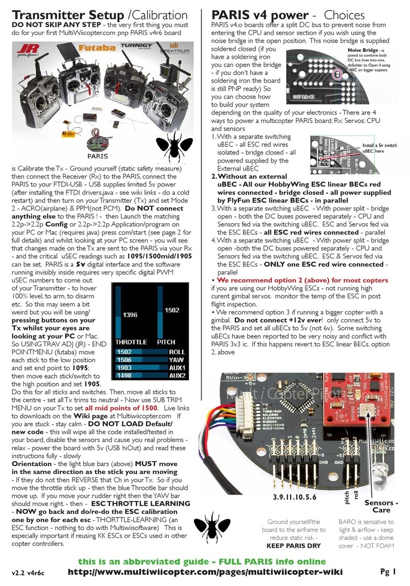
MultiWii
MultiWii PARIS Setup and Calibration Instructions
Calian
Calian SatService sat-nms ACU-19V user manual
Omron
Omron E5ARER user manual
HGLRC
HGLRC Zeus F722 manual
Emerson
Emerson TESCOM 04 Series Safety, Installation, Operations & Service
Comar Condensatori
Comar Condensatori QSR4 user manual
Mitsubishi Electric
Mitsubishi Electric MELSERVO MR-JET-G-N1 user manual
