1 FUNCTIONS AND CONFIGURATION
1.1 Outline 7
1
Control mode
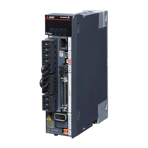
The servo amplifier supports the following control modes.
Compliance with standards
The servo amplifiers comply with the standards shown below. For the descriptions which are not in this manual, refer to the
following standards.
*1 It complies with the items in CDP (CommonDeviceProfile) in the standards for servo amplifiers with firmware version D4 or later.
Control mode Symbol Description
Cyclic synchronous position mode csp This is a control mode to drive servo motors by receiving a position command cyclically via either
synchronous or asynchronous communication with a controller.
Use an absolute position address for the command.
Cyclic synchronous velocity mode csv This is a control mode to drive servo motors by receiving a speed command cyclically via either
synchronous or asynchronous communication with a controller.
Cyclic synchronous torque mode cst This is a control mode to drive servo motors by receiving a torque command cyclically via either
synchronous or asynchronous communication with a controller.
Profile position mode pp This is a position control mode where an end position command is received to drive the servo motor in
either the synchronous or asynchronous communication with a controller. Use an absolute position
address or a relative position address for the command.
Profile velocity mode pv This is a control mode to drive servo motors by receiving a target speed command via either
synchronous or asynchronous communication with a controller.
Profile torque mode tq This is a control mode to drive servo motors by receiving a target torque command via either
synchronous or asynchronous communication with a controller.
Point table mode pt This is a control mode to drive servo motors according to commands such as travel distance and speed
which are stored in the point table number specified via either synchronous or asynchronous
communication with a controller. This control mode is not in CiA 402 standard (Mitsubishi Electric
original).
Available on servo amplifiers with firmware version B8 or later.
JOG operation mode jg This is a control mode where the servo motor speed is set to drive the servo motor manually via either
synchronous or asynchronous communication with a controller. This control mode is not in CiA 402
standard (Mitsubishi Electric original).
Available on servo amplifiers with firmware version B8 or later.
Homing mode hm This is a control mode to perform homing with the method specified by the controller.
Standards Version
ETG.1000.2 EtherCAT Specification - Part2
Physical Layer service definition and protocol specification
V1.0.4
ETG.1000.3 EtherCAT Specification - Part3
Data Link Layer service definition
V1.0.4
ETG.1000.4 EtherCAT Specification - Part4
Data Link Layer protocol specification
V1.0.4
ETG.1000.5 EtherCAT Specification - Part5
Application Layer service definition
V1.0.4
ETG.1000.6 EtherCAT Specification - Part6
Application Layer protocol specification
V1.0.4
ETG.1020 EtherCAT Protocol Enhancements V1.2.0
ETG.1300 EtherCAT Indicator and Labeling Specification V1.1.1
ETG.2000 EtherCAT Slave Information (ESI) Specification V1.0.10
ETG.6010 Implementation Directive for CiA 402 Drive Profile V1.1.0
ETG.5003.1 Semiconductor Device Profile - part1 CommonDeviceProfile*1 V1.1.0
ETG.5003.2 Semiconductor Device Profile - part2 Firmware Update V1.0.1
IEC 61800-7-201 Adjustable speed electrical power drive systems –
Part 7-201: Generic interface and use of profiles for power drive systems –
Profile type 1 specification
Edition 2.0
Adjustable speed electrical power drive systems –
Part 7-301: Generic interface and use of profiles for power drive systems –
Mapping of profile type 1 to network technologies
Edition 2.0


