BATTERYBOX SmartAim Supreme Series User manual

version: EN001/2019
SUPREME
PRODUCT RANGE
FIRE SAFETY - Do not place the device near flammable materials such as fabric, paper, straw
or plastic film. Flammable materials should be placed at a minimum distance of 500mm from
the top.
Do not place any electronic equipment sensitive to radio frequency and electromagnetic
interference near the device.
Wiring preparation:
All electrical connections must be in accordance with local and national standards and
regulations. The cable compartment is at the back of the device, including cable entries to
facilitate the installation of wires / cables.
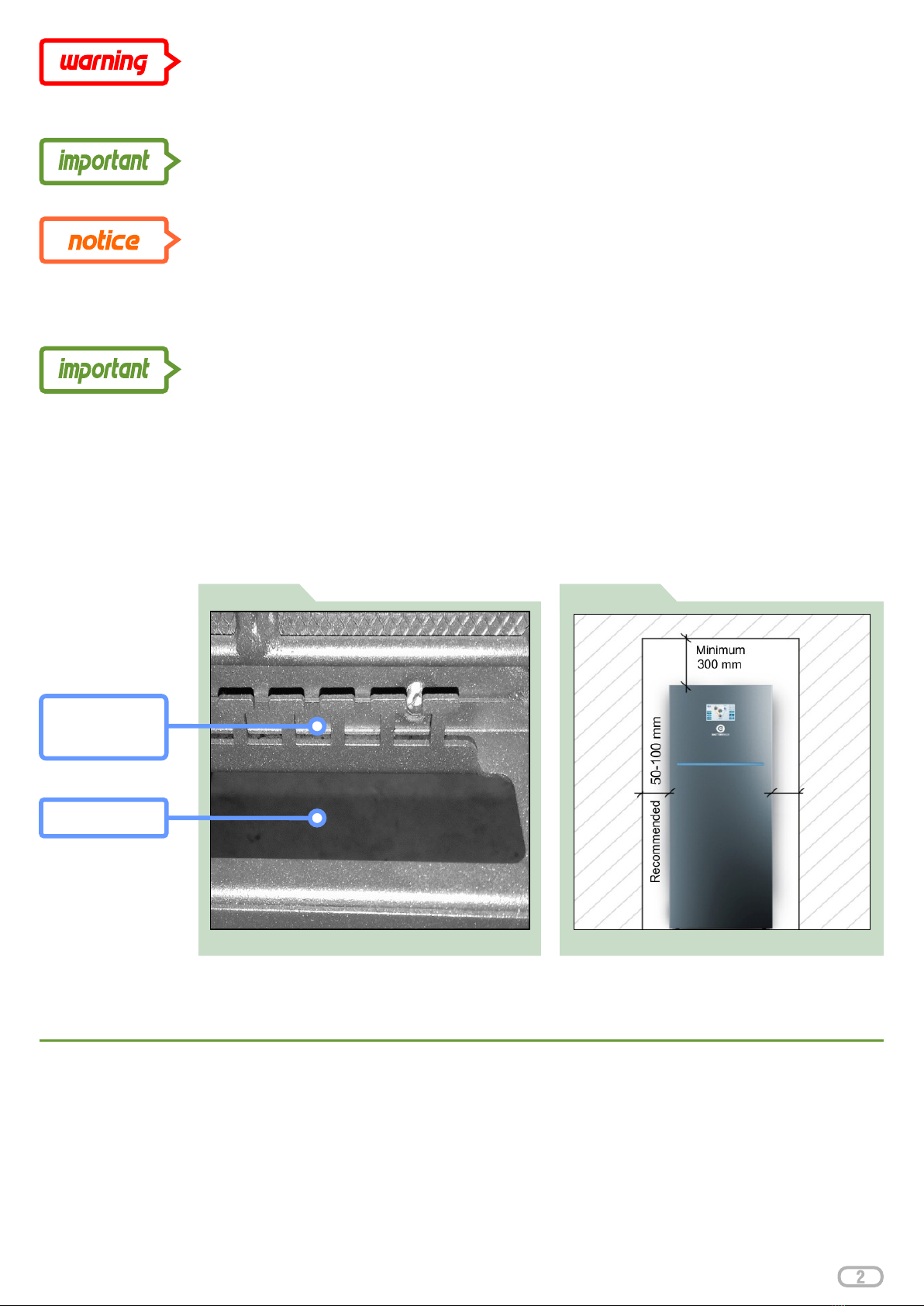
Do not drill, cut openings into the device. Use only the cable entries provided for the wiring and
cables. (Figure: 1)
Photo of SmartAim cable compartment Minimum space requirements for iinstallation.
FIGURE 2
Minimum space requirements
Recommended minimum clearance on each side is 100mm. Provide a minimum clearance of
300 mm around the top to provide adequate ventilation. Ventilation openings must not be
covered by foreign objects. The premises in which the device is located must have adequate
ventilation. (Figure: 2)
Installation of SmartAim
The device is designed for vertical mounting. The surface must be strong enough to carry the
weight of the device.
Recommended configuration of PV panels:
SmartAim is designed to use polycrystalline or monocrystalline panels. Poles of the PV panels
must NOT be grounded and leakage currents must NOT leak from the panels into earthed
structures. The OIGP configuration program is used to design the number of panels per MPPT
controller.
FIGURE 1
Cable ridge for
fastening cables
with cable ties
Cable opening
Please consider the environment before printing this document

Detail of DC photovoltaic panel connection to
FIGURE 3
device – DC terminal block.
String1:
XMPP: + / -
String 2:
XMPP: + / -
DC Connection
This section describes how to connect DC
photovoltaic panels to the device. DC
cables must be installed by a qualified
installer. (Figure: 3)
DC terminal block includes 4 terminals:
String 1: XMPP1: + / -
system voltage 350V - 800V
String 2: XMPP2: + / -
system voltage 350V - 800V
Recommended cable type:
solar conductor with PU insulation 2.5- 6
mm. The device has string 1&2 DC current
protection (see device datasheet),
including auxiliary contact and category II
surge protection, including auxiliary
contact.
For safe and efficient operation, it is very important to use suitably rated conductors to connect
photovoltaic panels. Risk of electric shock: Make sure that all DC circuit breakers are in the
OFF position. Never touch the terminals of the device. This will cause a fatal electric shock. To
avoid electric shock, do not touch the device when the photovoltaic panels are exposed to
sunlight.
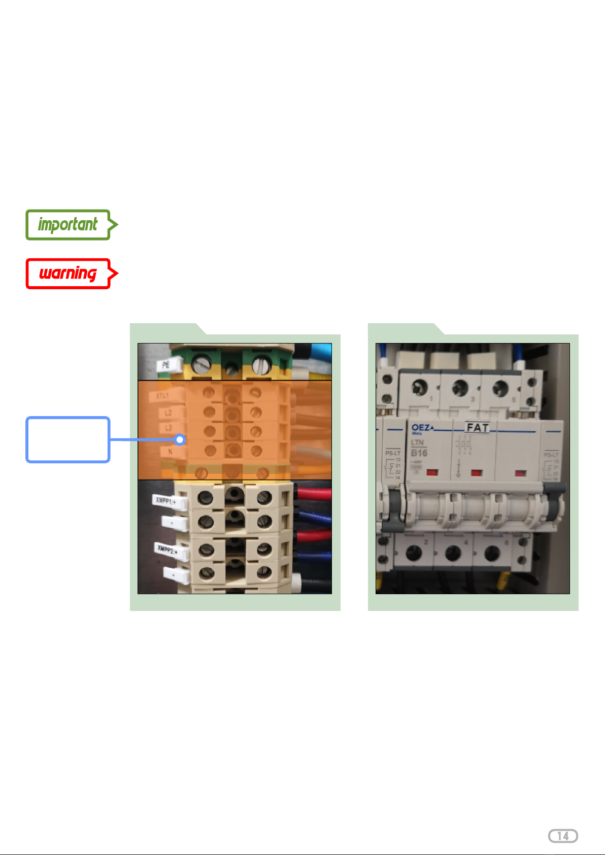
FIGURE 4
Detail of DC Photovoltaic Panel Connection to device — DC String protection.
String 2 protection
String 1 protection
Please consider the environment before printing this document

Before continuing, check that the cables are in the correct polarity: the positive
cable on the device is connected to the positive terminal and the negative cable is
connected to the negative terminal. (Figure: 5)
Device is not isolated, only the following types of photovoltaic panels (hereafter "PV
modules") can be used - monocrystalline and polycrystalline class A only. To prevent
malfunctions, it is necessary that PV panels with the option of leakage current to the inverter,
are not connected. For example, grounded PV panels cause leakage current to transmit to the
device. Maximum open field voltage: 900 V (900 V is the absolute maximum at low
temperatures, we recommend a maximum of 800 V during normal operation).
Follow the steps below to connect the PV panels:
1
2
5
6
7
8
3
4
Input Voltage / Polarity check Removing of cable insulation
FIGURE 6
FIGURE 5
CHECK BEFORE CONNECTING
SmartAim system !!!
Exceeding the maximum input voltage
may cause damage to the device.
Remove 8mm of the
insulation from the end of
the solar conductor.
Lead the DC wires to XMPP1 and XMPP2 strings.
Remove 8mm of the insulation from the end of the solar conductor. (Figure: 6)
Insert the end of the solar conductor into the end sleeve and fit it with crimping pliers.
Check the photovoltaic input voltage. Acceptable voltage at low temperatures: in normal
operation we recommend a voltage range of 350-800V and maximum current flowing to
the input terminals is 18.6 A
Turn off the FADC1 and FADC2 DC circuit breakers.
Connect one end of the photovoltaic panel cable to the positive (+) terminal XMPP1: +,
XMPP2: +. Observe correct voltage polarity.
Connect one end of the photovoltaic panel cable to the negative (-) terminal XMPP1: -,
XMPP2: -. Observe correct voltage polarity.
Please consider the environment before printing this document
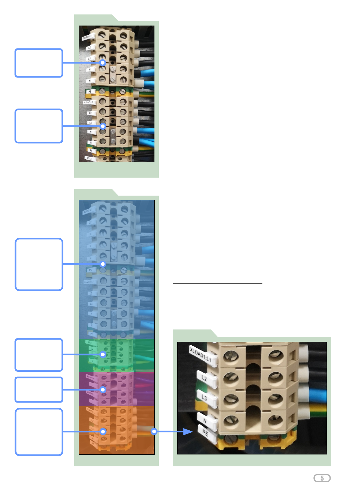
FIGURE 8
FIGURE 7
OUTPUT:
L1, L2, L3, N, PE
AC EPS/BACKUP connection
to device – AC terminal block
XLOAD:
AC GRID INPUT:
L1, L2, L3, N, PE
XGRID:
Overview of AC connection to device
AC INPUT /
up to 15 kW, with
EPS / BACKUP
OUTPUT
LOAD
input circuit
breaker up to 50A
breaker up to 50A
Detail of AC connection of NON-CRITICAL LOAD to device
FIGURE 9
AC Connection
This section describes how to connect the AC part to the
device. AC wires / cables must be fitted by a qualified
installer.
AC terminal block - contains 6 terminals: AC input (from
utility grid): XGRID: L1, L2, L3 N, PE
AC Terminal block EPS/BACKUP LOAD - contains 6
terminals: AC output to load (Load - max. 15kW with
available utility grid): XLOAD: L1, L2, L3, N, PE
(Figure: 9)
The AC terminal block NON-CRITICAL LOAD:
contains 5 terminals: AC output to load (Load – above
15kW, max. 50A supply): XLOAD1: L1, L2, L3, N, PE up to
10 kW in OFF GRID). (Figure: 7)
The EPS/BACKUP LOAD is connected to a load of up to
15 kW, including supply from the utility grid (up to 10 kW in
OFF GRID).
A measurable load above 15 kW can be connected to
the NON-CRITICAL LOAD. AC connection with
maximum input circuit breaker up to 50A.
The NON-CRITICAL LOAD is fed from PV production in
case of PV energy production surplus. (Figure: 9)
Recommended Cable Type:
Flexible 5x10mm CMSM Cable, minimum requirement
5x10mm Fixed Cable. The device has AC side
protection, including auxiliary contacts.
AC OUTPUT
over 15 kW, with
NON-CRITICAL
input circuit
LOAD
AC OUTPUT:
L1, L2, L3
XT:
DC Connection
String 2
String 1 &
(See page 14)
AC EPS/BACKUP
Please consider the environment before printing this document
Risk of electric shock: Make sure that all AC breakers are in the OFF position. For safe and
efficient operation, it is very important to use suitably rated cables for utility grid and load
connections. Use the double-insulated cables recommended above to reduce the risk of
injury . (See page 3)
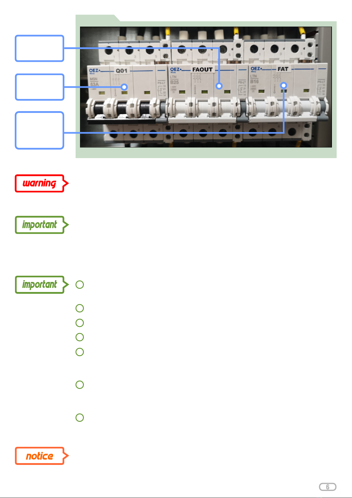
FIGURE 10
Detail of AC connection to device - AC protection
To reduce the risk of electric shock, ensure that the earth wire is properly grounded before the
device is operated on. This safety precaution should be followed, regardless of whether the
device is connected to the utility grid.
Q01:
main switch from
the utility grid
FAOUT:
load input
protection
FAT:
load input
protection - hot
water / auxiliary
output
Follow the steps below to connect the AC connection:
Check the mains voltage and frequency with a test meter. The data must match the
voltage on the label of the device.
Connect the AC power cables to XGRIG, XLOAD, XLOAD1.
Remove 10mm of the insulation from the end of the AC cable.
Switch off the AC circuit breakers Q01, FAOUT and FAT. (Figure: 10)
Connect the input power cable from the utility grid to the XGRID terminal block: L1, L2, L3 -
phase terminals – brown(L1), black(L2), grey(L3), N (neutral terminal - blue), PE terminal
(green and yellow). Observe correct polarity.
Connect the output power cable to the load / load unit XLOAD, XLOAD1: L (phase
terminals - brown(L1), black(L2), grey(L3), N (neutral terminal- blue), PE (terminal –
green and yellow). Observe correct polarity.
Before continuing, check that the cables have the correct polarity.
1
2
5
6
7
3
4
If the phase sequence and the clockwise field on the input of the device is not
adhered to, all loads will be covered by the device and the utility grid will be
unavailable.
Please consider the environment before printing this document
Control cables connection
This section describes how to connect a portion of the control part to
the device. Control cables must be installed by a qualified installer.
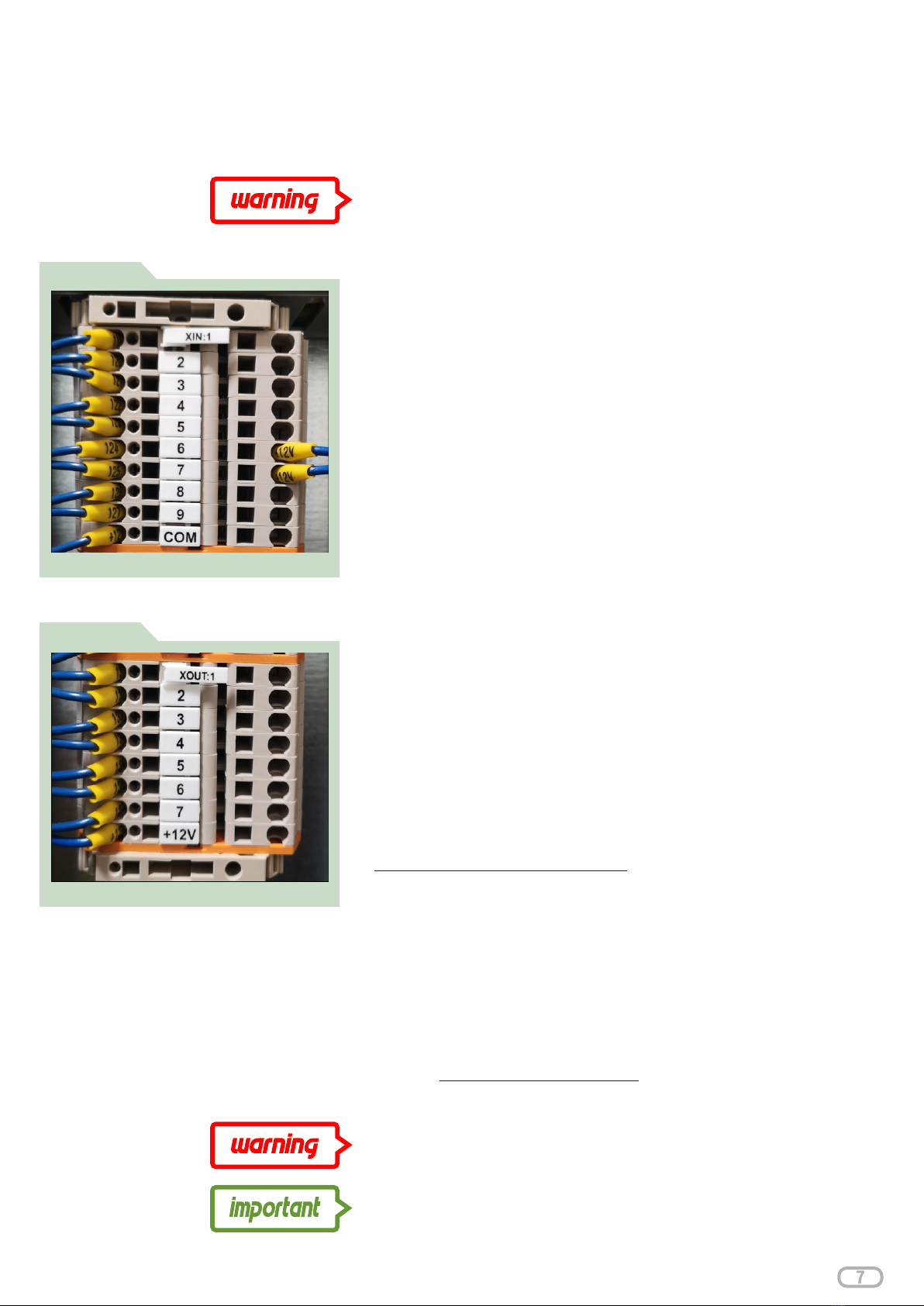
Overview of control input terminals
FIGURE 11
Overview of control output terminals
FIGURE 12
Control input terminals: XIN: 1, 2, 3, 4, 5, 6, 7, 8, 9 (Figure: 11)
XIN: COM - common terminal
XIN: 1 - signal (heat up water from grid - smart electricity tariff)
XIN: 2 - signal (charge the device from the grid – smart electricity
tariff)
XIN: 3 - safety stop. Device Safety Shutdown - After activating the
safety stop, the device switches the load off, utility grid and
photovoltaic panels. Under safe voltage remains: LCD, battery
bank and monitoring. After deactivating the safety stop, the device
will restart operation within 2 to 5 minutes.
XIN: 4 - power export control to utility grid in the range 0 - 100%
XIN: 5 - water heater - thermostat control
XIN: 6 - Manual unit bypass switch
XIN: 7 - Automatic unit bypass switch
XIN: 8 - spare 1
Control output terminals: XOUT: GND, 1, 2, 3, 4, 5, 6, 7 (Figure: 12)
XOUT: + 12V
XOUT: 1 - AUX 1 (programmable contactor)
XOUT: 2 - AUX 2 (programmable contactor)
XOUT: 3 - AUX 3 (programmable contactor)
XOUT: 4 - spare 1
XOUT: 5 - spare 2
XOUT: 6 - spare 3
XOUT: 7 - spare 4
Recommended control cable type: JYTY- ..x1
Risk of electric shock: Make sure all DC, AC circuit breakers and
fuse switch disconnectors are in the OFF position.
Connecting the batteries
This section describes how to connect a battery bank to the device.
DC cables and communication cables must be fitted by a qualified
installer. Recommended cable type: included
Risk of electric shock: Make sure all DC, AC circuit breakers and
fuse switch disconnectors are in the OFF position.
Incorrect DC and communication cable connections may
damage the unit.
Please consider the environment before printing this document

Battery Bank Wiring Example - Point 4-5
FIGURE 14
When connecting the battery bank, follow these steps:
Place the individual battery modules in the designated slots
in the device. (Figure: 13)
Install the battery modules with the supplied screws.
(Figure: 13)
Connect the individual battery modules with supplied CYA 6
green/yellow cables. (Figure: 13)
Connect the red wire to the positive terminal (+) and the
black wire to the negative terminal (-). (Figure: 14)
1
2
3
4
Connect the Link PORT 1 (first battery) communication
cable to Link PORT 0 (second battery). Then connect Link
PORT 1 (second battery) to Link PORT 0 (third battery), etc.
(Figure: 14)
5
Connect the CAN cable to the CAN PORT connector of the
top battery.
6
Make sure the wires are firmly connected. (Figure: 15)
7
6
Turn the power switch of each battery module to position 1
(ON position). (Figure: 16)
8
Battery Bank Wiring - Point 6-7
FIGURE 15
Press the SW button (on the top battery only) (Figure: 17)
9
Check the battery voltage at the DC fuse switch-
disconnector. The rated voltage is 48 V DC. (Figure: 17)
10
Battery Bank Wiring Example - Point 1-3
FIGURE 13
Battery Bank Wiring - Point 8
FIGURE 16
Battery Bank Wiring - Point 9-10
FIGURE 17
Risk of electric shock: Make sure all DC,
AC circuit breakers and fuse switch
disconnectors are in the OFF position.
CAN
Communication
Please consider the environment before printing this document

Detail of grounding terminals
FIGURE 19
Overview of connection of communication
FIGURE 18
cable to device
Connection of communication cables
For cable communication between the device and a third party, it
is recommended to use a Cat 5e shielded communication cable.
It is because of the higher risk of interference, overlapping, etc.
The shielded communication cable is to be connected only on
one side of the connection for protective earthing.
It is not permitted to place communication cables near power
lines. If unable to keep the minimum distance of 0.15m, for
example use additional shielding in plastic channels.
These channels must have good conductivity throughout the
distribution and connected to the earth cable of the power lines.
Communication cables must be within 50mm of any part of the
low voltage circuit (230V AC).
When installing cables, avoid sharp bends, never break the
cable (e.g. in corners). For each cable type, the manufacturer
specifies the minimum bending radius - typically bending radius
min. 6 x cable diameter, do not bend the cable more than 90 °.
The cables must not be subjected to mechanical pressure. Do
not exceed the permissible tensile limit when handling the
cables (through holes, channels). Stretching the cable with a
force greater than about 10 kg will cause damage by means of
pulling or twisting.
Cables should be laid so that they are mechanically protected.
Do not stretch the cables but rather leave them loose. Also,
frequent movements damage the cables.
Failure to observe the cable laying rules may result in slow data
transmission and interruption of the cable route. Due to the high
frequencies, a mere change in the geometrical arrangement of
the veins in the cable may cause obstruction of data
transmission. This can be the case despite the cable looking
operational to look at. Particularly sensitive to mechanical
damage are the points of the cable leading up to the connector.
In these places it is necessary to protect the cable from both
bending and axial pulling.
Device grounding/earthing
CY (CYA) 16 green / yellow cable must be connected from the
main PE earthing/grounding point, and it needs to be connected
to the main PE bus in the device. (Figure: 19)
All metal frames of the entire PV solar plant must be
interconnected, using CYA 10 green / yellow cables. In addition,
all Class I electrical equipment that is connected with the main
PE grounding point must be interconnected.
Please consider the environment before printing this document

Device wiring before the first parallel connection
1.1 Battery bank connection, power section (+/-), CAN communication (grey
communication cable from the device to the first battery and black communication
cables Link Port 1 to 0) (Figure: 20)
1.2 Grounding / Earthing after connection check (Figure: 20)
2.1 Turn power switches on the batteries to position 1 (ON position) (Figure: 20)
2.2 Press SW button to activate the batteries (always the top battery where the CAN
communication cable is connected). (Figure: 20)
A total overview of battery bank wiring according to initial commissioning
FIGURE 20
1.1
2.2
1.1
2.1
connection check
1.2
leave these CAN
ground / earthing
communication
ports empty
Please consider the environment before printing this document
Battery bank wiring

SmartAim unit connection, LAN cable connection (switch or router)
Measure voltage on XMPP1 terminals
Measure voltage on XMPP2 terminals
Switch on the 1FADC circuit breaker
Switch on the 2FADC circuit breaker (keep the circuit breaker switched on if
string ll not connected: otherwise it signals alarm and indicates a fault in the
Service Portal
Measure voltage per phase 1 to 3 on terminals XGRID
Switch on the main switch
Check the right connections using the Bypass function
Turn on the main output circuit breaker FAOUT
Measure voltage on terminals XLOAD
Overview of cabinet wiring
08
05
04
09
07
06
10
03
02
01
01
02
03
04
05
06
07
08
09
10
Overview of cabinet wiring - Wiring Diagram
Please consider the environment before printing this document
Wiring Diagram
FIGURE 21
DIAGRAM
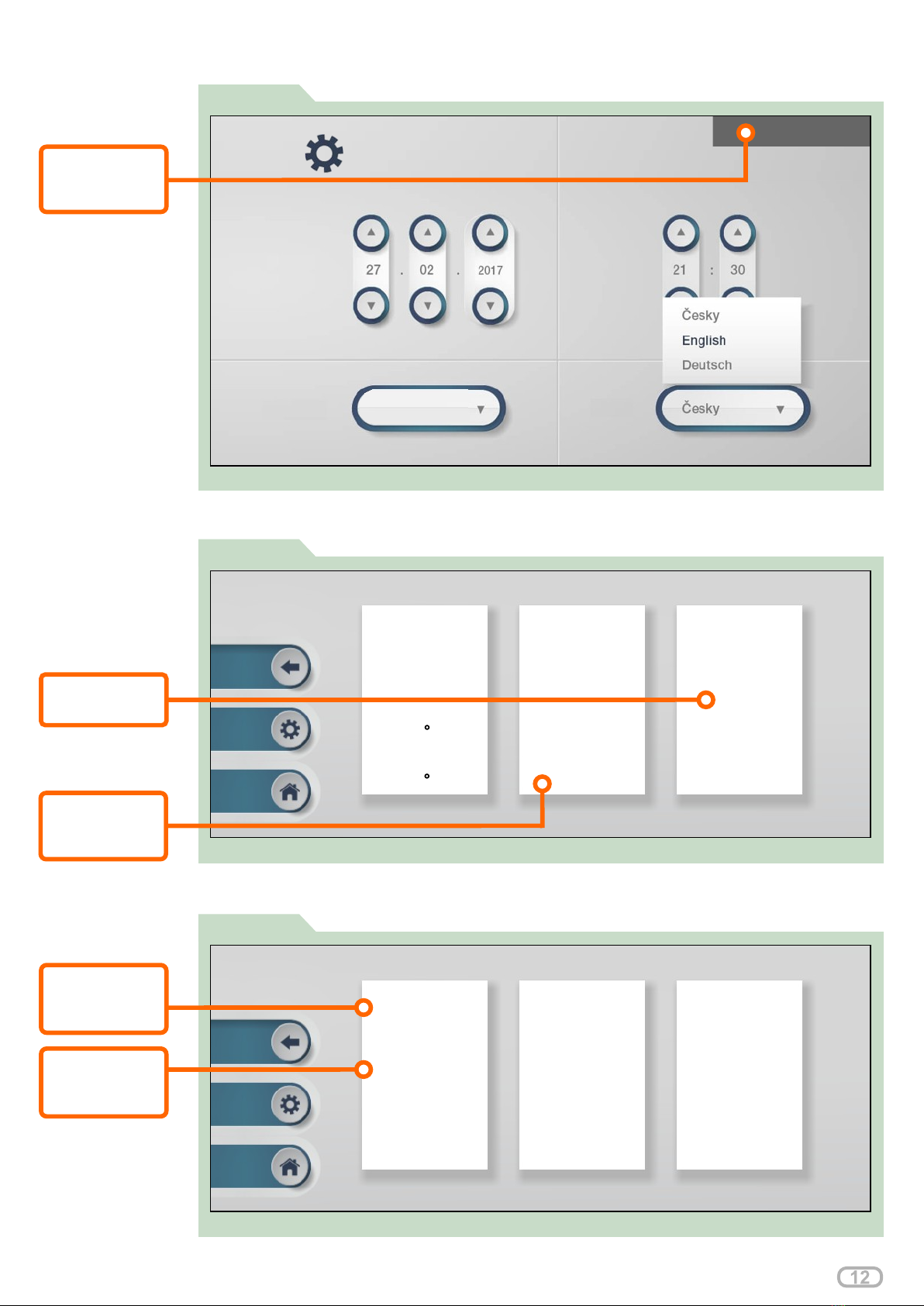
FIGURE 22
FIGURE 23
FIGURE 24
CONTROL PANEL SETUP
Firmware version check
IP address / batteries state of charge check
PV Power and Battery Power adjustment
Please consider the environment before printing this document
IP ADDRESS
check
AC CHARGE
THRESHOLD
check
SOLAR PV
ajustment
CAPACITY
ajustment
STORAGE
FIRMWARE
check
VERSION
User interface: Firmware version check
SETTINGS
Date Time
Ethernet Language
v.3.0.41
SIZE
User Interface: PV Power and Battery Power adjustment
Inverter ON/OFF
Active
Password
0
LCD Reset
Inactive
Solar PV size
9800W
Grid Capacity
10000W
Charge Capacity
10000W
Storage Capacity
7200Wh
Battery Shutdown
20%
Grid > Battery
15%
Generator > Battery
AC Charge
Unit ID
717013002
Port
5710
Domain
0
IP Address
90.183.11.205
LED Brightness
20%
LCD Brightness
80%
Ventilator 1
Ventilator 2
40 C
37 C
charge threshold
safe threshold
15%
start threshold
60%
threshold
User Interface: IP address check
Formating of the batteries
Pressing the "Formatting" button will start formatting. The initial screen will (Figure: 25)
take up to 2 minutes to take effect. An animation in the form of arrows (from grid to
batteries) shows up, meaning the batteries are being charged from the utility grid
(Figure: 26). The number of Watts (below the battery icon) start to increase and the total
storage capacity value changes.
Check the charge status of the batteries vs. "AC Charge threshold". To start (Figure: 25)
formatting, the charge status of the batteries must be less than the "AC Charge
threshold" value. The charge status of the batteries is displayed on the right-hand side
of the screen.
FIGURE 25 Formating of the batteries
89%
78 %
contribution
67 %
Solar PV
Statistics
Weather
Settings
Mode
Alerts
Self-Sufficiency
Power Grid
Solar PV
1468 W 0 W
Battery Storage
15063 W
FIGURE 26
ARROW
arrow animation
from grid to battery
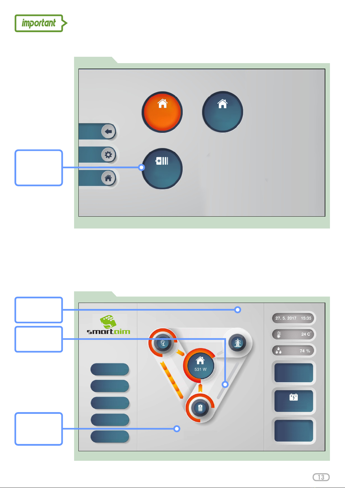
User interface - Home screen: Battery formatting
STORAGE
Watts increase
to battery
POWER GRID
Watts increase
from utility grid
Please consider the environment before printing this document
FORMATING
press the button
to initiate
formating of the
batteries
User Interface: Battery formating
Home Grid
Formating
1
Home Grid
2
BATTERY
Connection on XT power terminals
FIGURE 27
FAT circuit breaker set to one position
FIGURE 28
AC OUTPUT:
L1, L2, L3
XT:
Load selection, wiring and hot water settings
PV solar power primarily covers the load and recharges the batteries. In case of electricity
surplus to the utility grid, the auxiliary devices will activate according to your selected priority
settings.
It is possible to connect a single-phase or three-phase immersion heater. However, the
maximum power per phase is 2 kW. If a single-phase heater is used, 6kW value must be
entered in the Power Output settings. The system always divides into thirds. In case a 2kW
value is entered, then the maximum output per phase is 666W.
If a three-phase electrical immersion heater is connected, it must be star-wired, i.e. 3x230V
(not in a triangle at 400V).
If no immersion heater is not connected, leave the FAT circuit breaker switched on. (Figure: 28)
(otherwise it indicates a fault in the ).Service Portal
From the Home Screen select SETTINGS . Select the immersion heater (Figure: 26)
icon and another screen will be displayed. Immersion heater (Figure: 29) (Figure: 30)
activation is performed by touching the On / Off icon . The immersion (See Table 1)
heater icon turns when switched on. orange (Figure: 30)
Refer to for the function of each button. Priority 0 is the factory default Table 1
setting (0 = first priority). In order for the immersion heater function to operate, it
is necessary to have a power set and the On/Off icon on . If you want to use orange
a smart electricity tariff to heat your water, this can also be performed from the
screen. Once your smart periods have been selected, the system will become
active.
Please consider the environment before printing this document
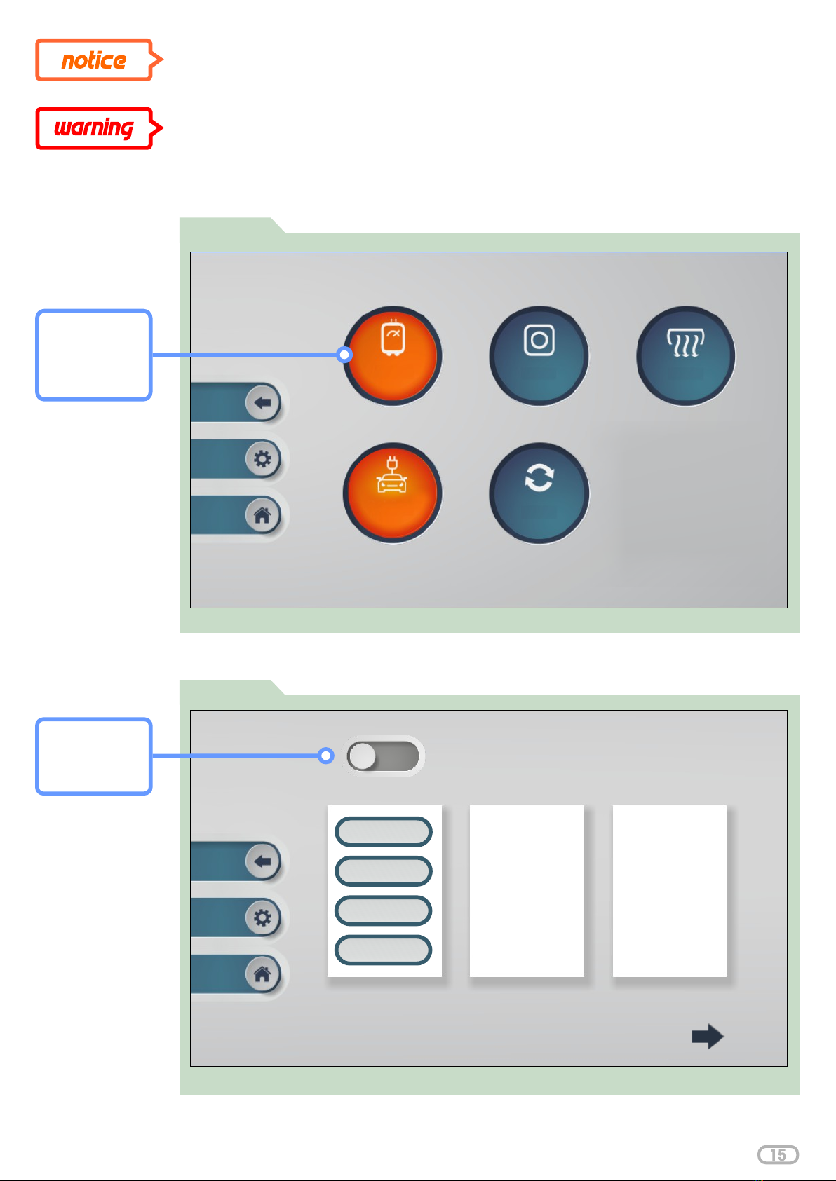
Immersion heater load settings
Immersion heater settings and status
DO NOT FORGET TO TURN OFF MANUAL MODE, OTHERWISE SMART
ELECTRICITY TARIFF SETTINGS WILL NOT WORK
Immersion heater can be switched manually to test its functionality. (Figure: 29, 31)
Please consider the environment before printing this document
HEATER
select Immersion
heater button to
access settings
FIGURE 30
SETTINGS:
ON / OFF
activation of
immersion heater
Priority
IMMERSION HEATER
Power Output
Time Band 1
Time Band 2
Power Output
8W
Priority
0
Time Band 1
01:00 - 08:00
Time Band 2
18:30 - 23:30
Required Power
100 W
Smart Tariff
Active
Thermostat
ON
Consumption
0 Wh
Individual functions for immersion heater settings
Immersion
Heater
Heat Pump
Air Con
EV charger
MHRV
Ventilation
Overview of individual functions in the load settings
IMMERSION
FIGURE 29

Immersion heater settings and status
TABLE: 1: IMMERSION HEATER SETTINGS
Please consider the environment before printing this document
TABLE 1
Priority
Power output
Time Band 1
Time Band 2
Required Power
Consumption
Thermostat
Manual Mode
Priority management settings. A lesser priority (eg: 1) will be regulated when an
energy surplus is detected in the utility grid and the immersion heater control is
activated. Upon termination of priority 1 and other overflows to the grid, priority 2 will
be regulated.
Power output setup of the immersion heater. Max. 3x2kW / 3x230V in three-phase
and 6kW in single-phase.
Select a specific time to heat water. This is particularly useful in combination with
smart electricity tariffs. When a time period is set, water is heated regardless of PV
solar production. To activate this function, it is necessary to enable XIN 1 on the
control input terminals.
Amount of energy (kW) the user wishes to send to the immersion heater (6kW
max.)
Amount of daily energy (kW) being provided.
Water temperature. Enable XIN 5 on the control input terminals to activate.
Manual ON/OFF control: when selected manually, it activates the immersion
heater.
Set your surplus energy threshold for the immersion heater to activate.
ON/OFF button for the immersion heater
Select another specific time to heat water. This is particularly useful in combination
with smart electricity tariffs. When a time period is set, water is heated regardless of
PV solar production. To activate this function, it is necessary to enable XIN 1 on the
control input terminals.
Start energy
Settings and status display for immersion heater
Manual Mode
IMMERSION HEATER
Start Energy
Manual Mode
Active
Start Energy
200 W
FIGURE 31
SETTINGS:
ON / OFF
activation of
immersion heater

In order to be able to manage SmartAim via the APP, you need to establish
connection with your internet network.
SmartAim allows dynamic and static IP address allocation.
Connection
The network cable from your local network is connected to a pre-
configured Ethernet switch or RJ connector in the router. After (Figure: 32)
connecting the network cable, the device automatically actives.
Internet connection
When the access point is activated, it will be automatically paired with the
data box. All device data including remote control data will be sent to the
data box. The data box setup is part of the factory settings.
IP address of the data box: Port: 90.183.11.205 5710
SmartAim - AVAILABLE WITH ACCESS POINT MIKROTIK
The Internet connects directly to the power cube to a free LAN connector.
(Figure: 32)
Please consider the environment before printing this document
FIGURE 32 Internet connection
Photo of internet connection
CONNECTOR:
use the free LAN
connector
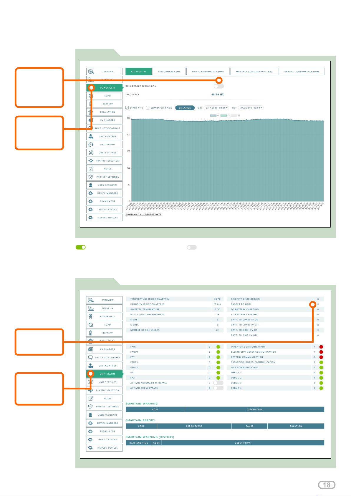
Export limitation
FIGURE 34
Allowing surplus energy to grid Preventing energy surplus to the grid
Surplus to grid is displayed on the "STATUS" tab on
Please consider the environment before printing this document
Adjust your settings on the Service Portal in section
Displaying status of surplus energy to grid using the service portal
VALUE:
value: 0 = OFF
value: 1 = ON
MENU:
“UNIT STATUS”
tab
select
FIGURE 33
Settings for surplus energy to grid using the service portal
BUTTON:
turn ON / OFF
to Allow / Prevent
MENU:
“POWER GRID”
tab
select
export electricity
to utility grid
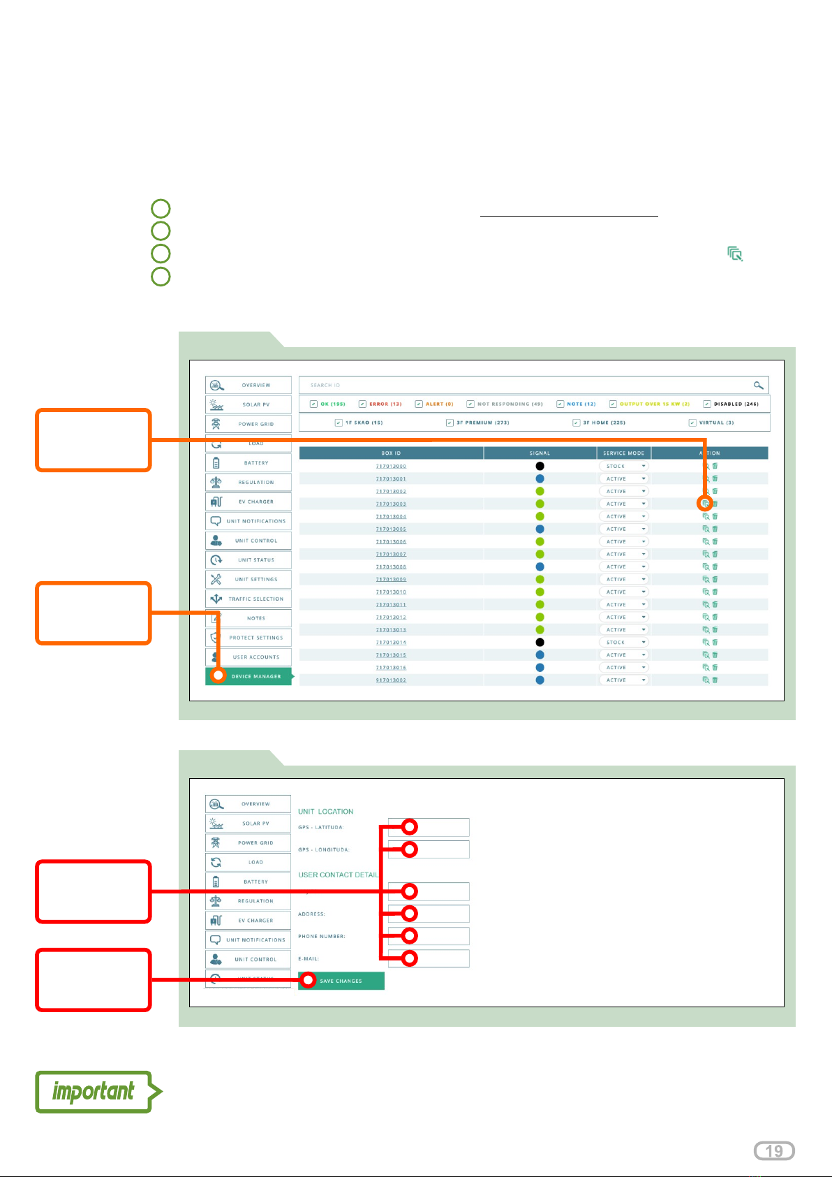
FIGURE 35
Device Manager tab
Register the device following the steps: (Figure: 35, 36)
Log in to your Service Portal account on servis.oigpower.cz/en/
1
2
3
4
Select DEVICE MANAGER tab from the main menu
Click the line tab or action icon on device you wish to register (Figure: 35)
Fill the registration form and click SAVE CHANGES button to apply changes
(Figure: 36)
SMARTAIM UNIT REGISTRATION
If the user does not want to use the application on a mobile device (does not register as a
user), the installer can perform the registration in the service portal. This step identifies the
device and does not prevent a future user registration.
Register SmartAim if the user refuses to register to assure free 24/7 unit monitoring,
maintenance and repair via manufacturers CMO (Central Monitoring Office) .
Please consider the environment before printing this document
BUTTON:
turn ON / OFF
to Allow / Prevent
MENU:
select “DEVICE
MANAGER” tab
FIGURE 36
Screenshot of device registration form
FIELDS:
fill in the blank
fields
BUTTON:
Save to apply
changes
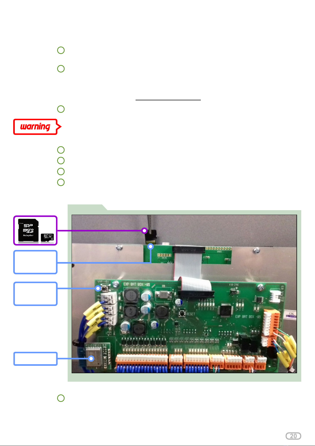
FIGURE 37 Demonstration of insertion of microSD card
Demonstration of insertion of microSD card
1
2
3
4
Ensuring the availability of the OIGpower or OIGpower Wi-Fi network. The name
of the internal Wi-Fi network in the device can be found using a smartphone or
personal PC. The name of the OIG power or OIGpower network is given by the
type of the router inside the device. The access point name must be found to enter
the SSID in the system. Password for access: . 10401947
Upload a file to the micro SD card that is designed for your device type.
ATTENTION! YOUR INTERNET CONNECTION MAY BE LOST AFTER THE
UPDATE IF THE ACCESS POINT NAME IS INCORRECT.
Open the door and remove the cover (unscrew 8 nuts)
SOFTWARE UPDATE
If the installer is updating the device, it is necessary to follow the steps below.
Component needed for updating - Micro SD card (recommended capacity up to
4GB, type – transcend)
Wi-Fi module
LCD SLOT
for micro SD
card
5Remove the Wi-Fi module from the expansion board slot (Figure: 37)
6Insert the micro SD card into the LCD slot (Figure: 37)
7Insert the Micro SD card in the LCD slot and press the reset button (Figure: 37)
8After the reset, the update package will be updated. The LCD must display an
update - "PPF Processing". If PPF-Processing is not displayed, the problem is in
the micro SDcard.
RESET
press the reset
button
Please consider the environment before printing this document
Table of contents


