Battle-axe ZF-35-D User manual

October, 2016

Operation Manual
2
2
Contents
1、Applications and Features3
1.1 Applications:............................................................................................................................... 3
1.2 Structure Features:..................................................................................................................3
2、Main Specifications................................................................................................................................. 4
2.1 Dimension:.................................................................................................................................. 4
2.2 Specification Chart:..................................................................................................................4
3、Installation and Test...............................................................................................................................5
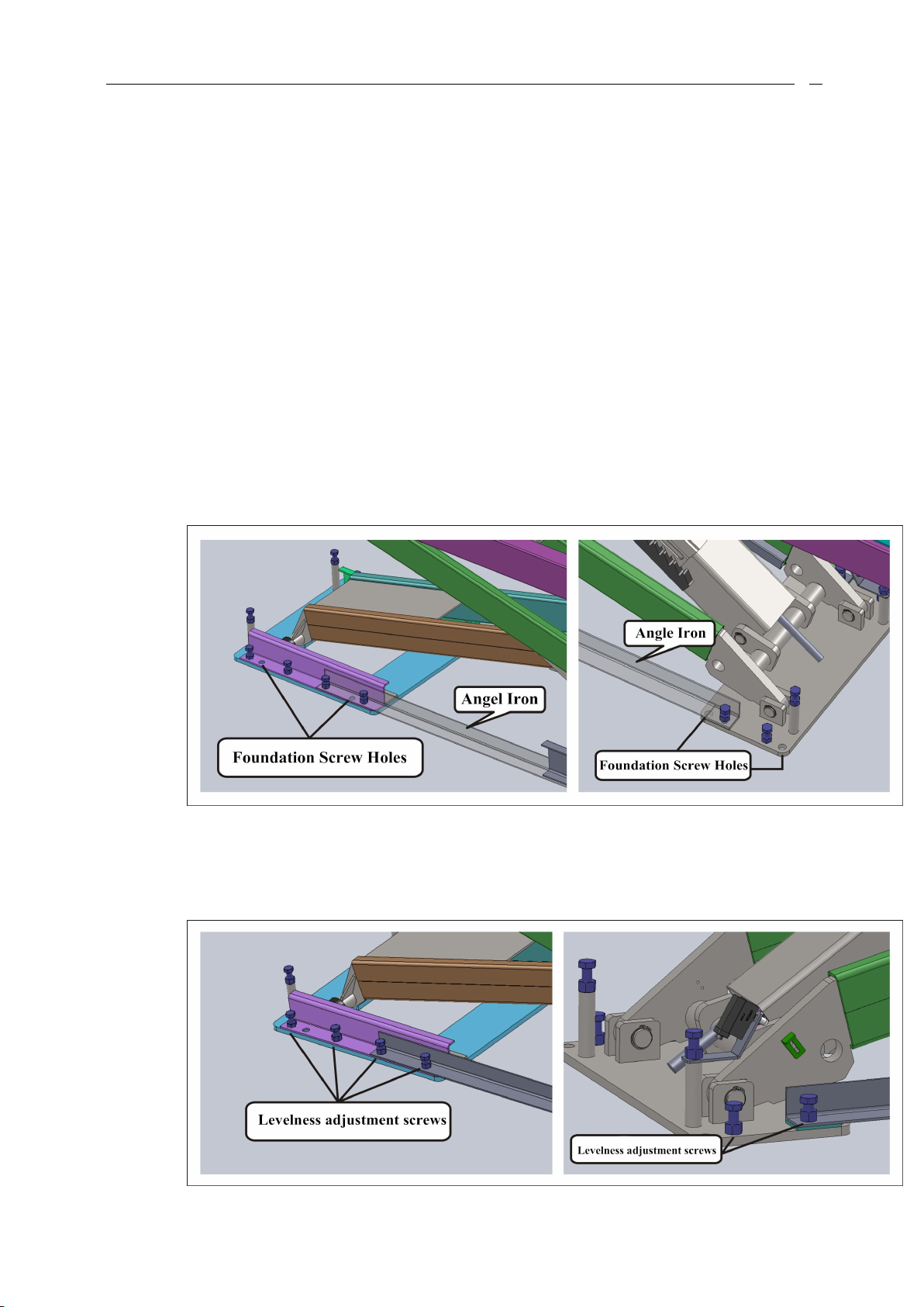
3.1 Foundation Preparation:.........................................................................................................5
3.2 Hydraulic Oil Filling:.................................................................................................................7
3.3 Connection of Power Supply and Air Supply:................................................................7
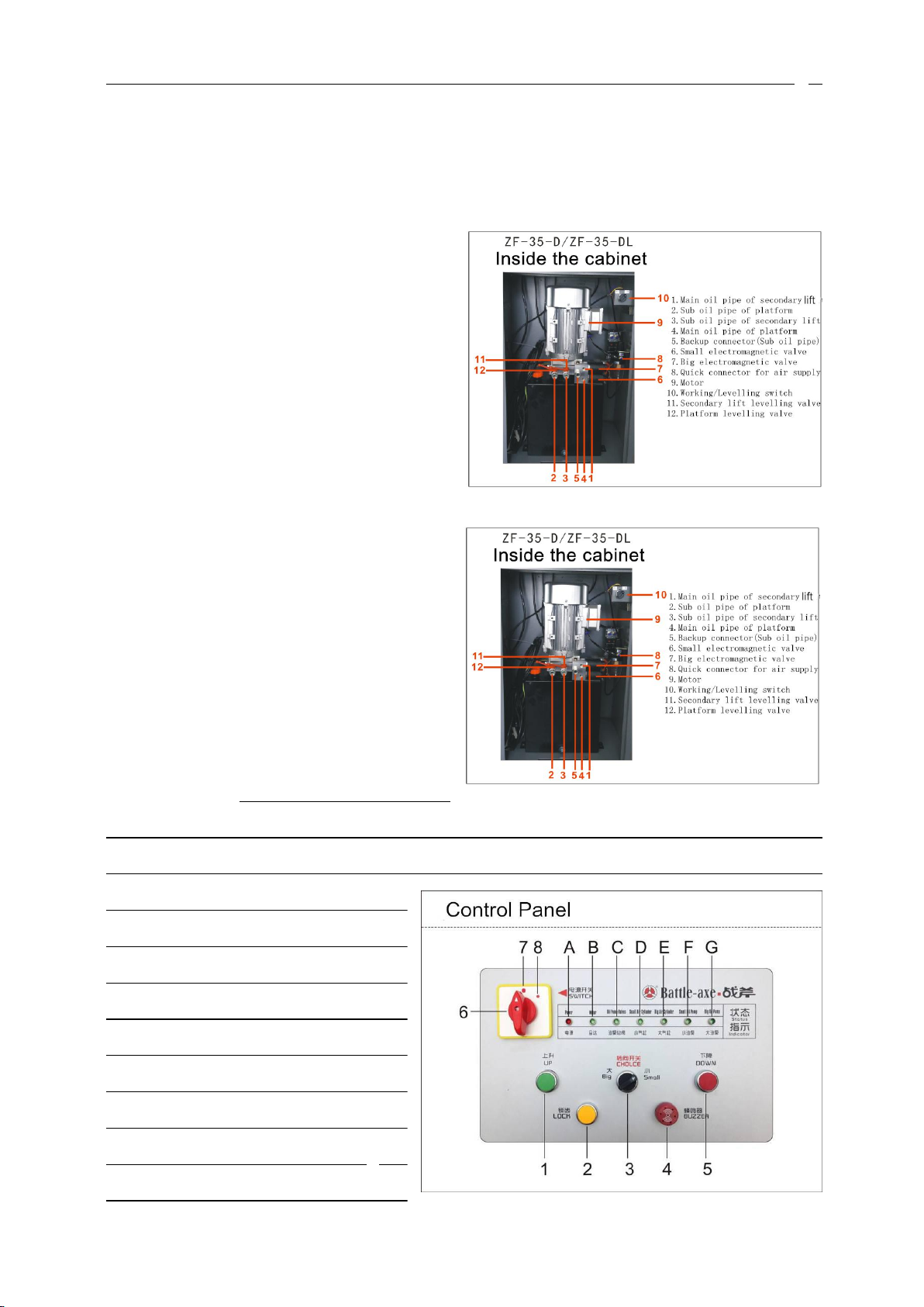
3.4 Installation Procedures of the Oli Pipe between Lift and Control Cabinet:.......8
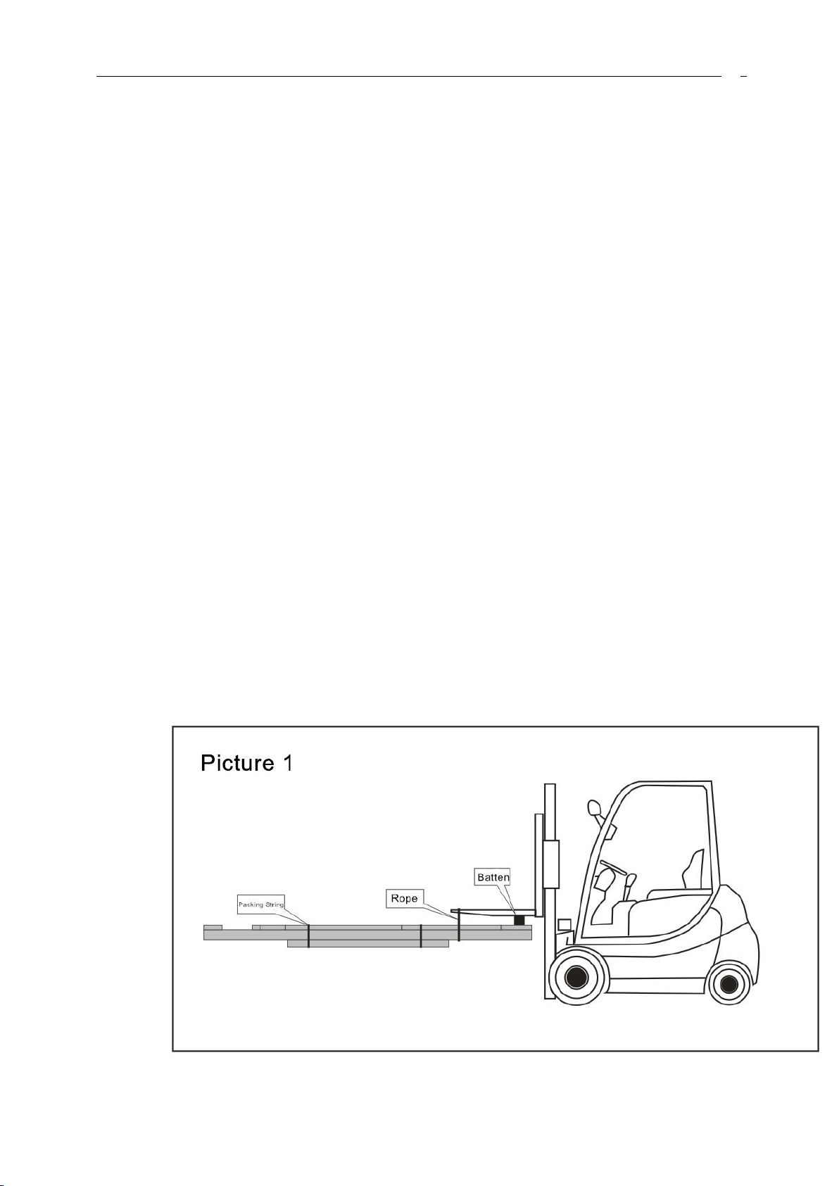
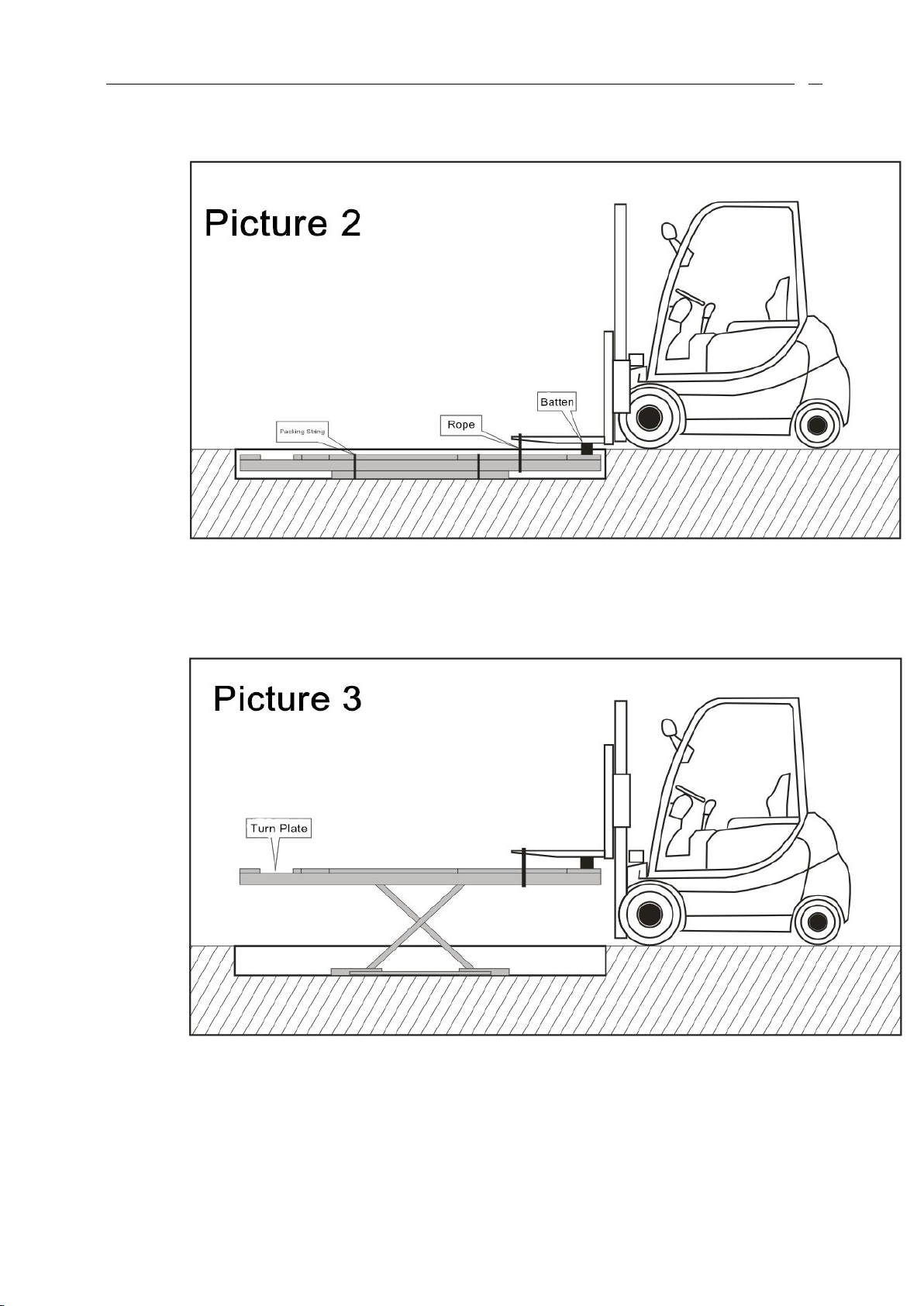
3.5 Placing the Lift in the Pit:...................................................................................................... 9
3.6 Oil filling, Exhaust and Levelling of the Platfrom:.................................................... 12
3.7 Oil filling, Exhaust and Levelling of the Secondary Lift............................................ 15
3.8 Installation and Adjustment of Limit Switch:............................................................. 15
3.9 Loading Test:......................................................................................................................... 156
4、Care and Maintence............................................................................................................................. 16
5、Matters need attention during operation.................................................................................... 16
6、Operation Instruction..........................................................................................................................17
1、UP:....................................................................................................................................................18
2、LOCK:.............................................................................................................................................. 18
3、CHOICE............................................................................................................................................. 18
4、BUZZER.............................................................................................................................................19
5、DOWN................................................................................................................................................19
6、SWTCH.............................................................................................................................................. 19
7、INDICATORS A-G.......................................................................................................................... 19
7、Oil Refilling:.......................................................................................................................................... 19
8、Manual descend in case of power failure:................................................................................20
9、Failure Recovery Operation:...........................................................................................................21
10、Foundation drawing:.......................................................................................................................23
11、Oil pipe conneciton drawing:.......................................................................................................25
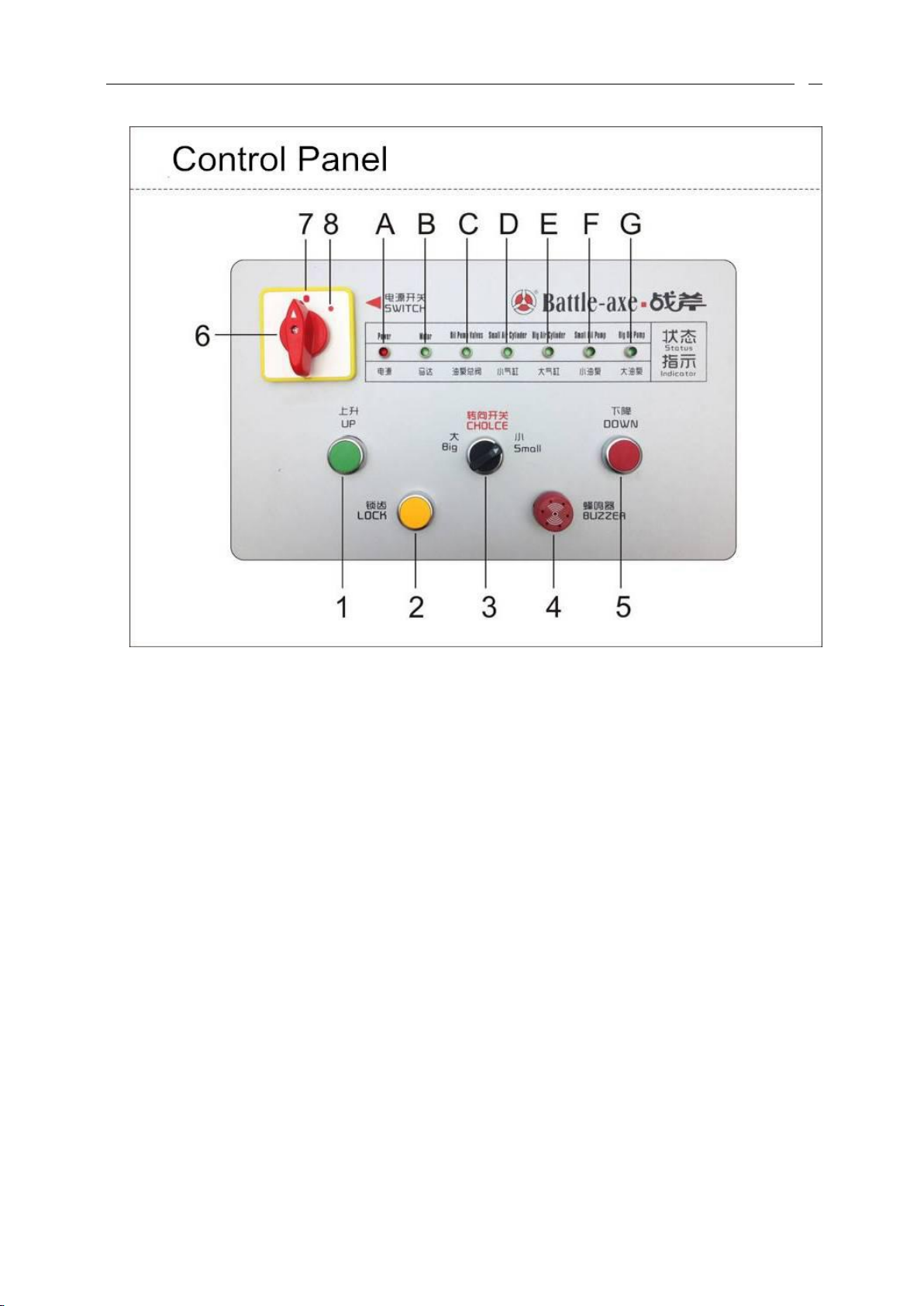
12、Control Panel:....................................................................................................................................26
All right reserved

Operation Manual
3
3
1、Applications and Features
1.1 Applications:
ZF-35-D/DL hydraulic scissor car lifts are applied for lifting all types
of light vehicles that weight not over 3500kg. They are suitable for four
wheel alignment, inspection, maintenance and caring of all levels of
vehicles, in vehicle maintenance shops and tire shops。
1.2 Features:
Hidden scissor structure. Space saving.
Same capacity in main and sub Cylinders. Making two platform working
steady and synchronously.
Double Safety Device: Hydraulic lock and double teeth gripper. Locking
guarantee whenever the descending stops.
Safety valve in case of Hydraulic failure and overload.
Safety device in case of pipe explosion. Making the lift descend slowly
instead of falling fast in case of the oil pipe explosion.
Slide blocks are made from super wear-resistant material, 。
Most of electronic and Hydraulic parts are imported from Italy,
Germany and Japan.
Outstanding Levelness adjustment ability. Level degree Accuracy can
be adjusted. So it is very suitable for wheel alignment.
Manual descending device in case of power failure.

Operation Manual
4
4
2、Main Technical Parameters
2.1 Dimensions:
2.2 Specification Chart:

Operation Manual
5
5
3、Installation and Test
3.1 Foundation Preparation:
Model
ZF-35-D / ZF-35-DL
Driving method
Electricity and Hydraulic pressure
Platform Rated Lifting Capacity
3500kg
Secondary Lift Rated Lifting Capacity
3500kg
Platform Lifting Height
1850mm
Secondary Lift Lifting Height
500mm
Platform Min Height
330mm
Platform Length
4200mm / 4500mm
Secondary Lift Length
1500mm
Single Platform Width
600mm
Single Secondary Lift Width
600mm
Platform Ascending Time
≤50s
Platform Descending Time
≤60s
Secondary Lift Ascending Time
≤30s
Secondary Lift Descending Time
≤20s
Overall width
2070mm
Overall Length
4200 mm / 4500mm
Net Weight
2000kg / 2100kg
Power Supply
AC 380V±10% 7A or 220V±10% 11A 50/60Hz
Motor Power
2.2kw
Hydraulic Oil
46#wear-resistance Hydraulic Oil (not included with
shipment)
Air supply pressure
6-8kg/cm2
Working temperature
5-40℃
Working Humidity
30-95%
Working Noise
< 50db
Installation Altitude
≤1000M
Storage temperature
-25℃~55℃

Operation Manual
6
6
The thickness and levelness of concrete foundation is crucial.
The levelness adjustment ability of the equipment is limited.

Operation Manual
7
7
3.2 Hydraulic Oil Filling:
Fill the hydraulic oil into the oil tank. (The oil is not included in the shipment)。
3.3 Connection of the air supply and electricity:
3.3.1 380V Power supply connection:Connect the power line to“负载端”on the
earth leakage circuit breaker.
Attention:Power line specification:≧2.5mm².
3.3.2 220V Power supply connection:Connect the power line with “N” and any
one of three phase conductor in the “负载端”on the earth leakage circuit
breaker。Attention:Power line specification:≧4mm².
3.3.2 Air supply connection :Connect the air pipe with quick coupling in the

Operation Manual
8
8
control cabinet.
3.3.3 Air Pressure:4~6kg/cm²
3.4 Installation Procedures of the Oil Pipe between Lift and Control Cabinet:
Attention:Connector protection is the most crucial during oil poling. DO NOT
let any dirt or sundries get in to the hydraulic system, blocking the oil pipe.
3.4.1 Firstly turn the switch of “Level/Working”to“Working”condition。Turn
the“CHOICE”switch to “BIG”. Connect a bottle with the connector“④” of the
pump station,and then push “UP” on the control panel. If the hydraulic oil burst
from “④”connector in 5 seconds,Then it proves that the motor is rotating in right
turn. If there is no oil, or no sign of pressure when the oil comes out, then it proves
that the motor is rotating in the wrong turn. To solve this problem, please exchange
the position of the any 2 of 3 power lines in Red, Green and Blue in the Distribution
Box.
3.4.2 Firstly connect the oil pipe No.1 with the connector “ ④” of the pump
station 。And then push “UP” on the control panel, lift the platform to a
appropriate height at which the other pipes can be connected conveniently.
(Attention :Make sure the “Working/Level” is at “Working” position

Operation Manual
9
9
before you push “UP”)
3.4.3 Pull out the No.8 oil pipe from the control cabinet, connect the No.2 and
No.3 oil pipe under the equipment to the 3-way connector of the No.8 oil
pipe.
3.4.4 Connect the No.4 oil pipe under the machine with connector“①” of the
pump station.
3.4.5 Pull out the oil pipe No.7 from the control cabinet, connect the No.5 and
No.6 oil pipe under the equipment to the 3-way-connector of the No.7 oil
pipe.
3.5 Placing the lift in the pit:
3.5.1 The main lift must be placed in the pit closer to the control cabinet. There
are 4 oil pipes under the main lift, 2 oil pipes under the sub lift. The end with
turn plate groove should be opposite to the side on which the vehicle drives.
The side with logo and mark should be facing outwards. After confirmation
on installation position, tie the main lift to the forklift, as the picture1
shows(Do not unfold the packing string):
3.5.2 Place it in the pit and confirm its horizontal position. Cut off the packing

Operation Manual
10
10
strings like it shows in Picture2.
3.5.3 Lift the equipment at an appropriate height and confirm if the safety teeth are
locked, untie the rope and drive away the forklift referring to picture 3.
3.5.4 Connect the air pipe according to the instruction 3.4
3.5.5 Descend the lift to a height a little higher than the pit, pry and move the lift in
the pit to make sure the position of main and sub lift are suitable for

Operation Manual
11
11
installation.
3.5.6 Reconfirm that:if the lift is in the central position of the pit, if the main lift
and sub lift is parallel, if the front side and back side is aligned, if the length
of the diagonal lines are equal and so on. After above confirmation, the main
lift and the sub lift should be locked at the forth Safety tooth. And then drill a
hole at the depth of 120mm with a electric impact drill(Ф16 drill bit)
and install foundation bolt(16 pcs) Attention: DO NOT install expansion
screw firstly. The holes’ position of the foundation screws are shown in
below pictures. Some of the holes are covered by angle iron which is used
only as packaging protection. So the angle iron can be dissembled before
screws installation.
3.5.7 As it shows in below picture,place a steel plate beneath each horizontal
adjustment screw, making sure them have no directly contact with the
ground.

Operation Manual
12
12
How to place steel panel beneath the levelness adjustment screws:Lift up the
platform to an appropriate height. Support the platform with a wooden pillar as the
below picture shows. Then push “DOWN”. At this moment, the platform on the
supporting pillar will go up a little bit. Keep pushing “DOWN” little by little, until
the steel panel can be insert beneath the levelness adjustment screws. And then insert
it. With the same methods, insert steel plates beneath all the levelness adjustment
screws.
3.5.8 Levelness Adjustment :By observing the spirit levels or transparent
levelness pipelines and adjust the levelness adjustment screws at the two side
of the base panel at the same time, the position of two drawer boards and the
level degree at the front side can be adjusted. Confirm that the tolerance of
height difference between two platforms ≤3mm; The levelness lengths
difference, of the two runways at minimum height with the ones at maximum
height ≤10mm. And then install the central expansion screw to tighten the
foundation screws. The space between the ground and the base must be fully
stuffed with iron discs or cement mortar after the adjustment.
3.6 Oil filling, exhaustion and leveling of the platform:
Step 1:Turn the “Working/Leveling” switch to “Working”. The switch is the item No.10 in the
below picture.

Operation Manual
13
13
Step 2:Then Turn the “CHOICE” to “Big”. The switch is the item No.3 in below picture.
Step 3:And then push “UP” on the control panel, make the platform ascend to the maximum
height.

Operation Manual
14
14
Step 4:Turn the “Working/Leveling” switch to “Leveling”. The switch is the item No.10 in the
right picture.
Step 5:Turn anticlockwise and loose the No.12 Platform leveling valve.
Step 6:Then push “UP” on the control panel.
At this moment only the sub platform ascends.
Lift it up the 3rd locking tooth. After that push
“DOWN”, making the sub platform descend
to the minimum height. Repeat above
procedure for 3~4 times, in order to exhaust
the air in the main cylinder upper part and sub
cylinder. Then lift the sub platform to the
maximum height, and turn clockwise to
tighten the “Platform leveling valve” to finish
the exhaustion.
Step 7:At this moment the main/sub lift are
almost level. The leveling adjustment finish
after the “Working/Leveling” Switch is turned
to “Working”. [If the equipment is still no
level, push “DOWN” when the “Working/Leveling” points to “Working”. Making the platform
at the height of 1 meter. Then turn the “Working/Leveling” to Leveling, and turn anticlockwise
to loosen the “Platform Leveling valve”
After that, push “UP” on the control
panel. Remark: Normally, the sub
platform can be lifted a little higher than
main platform, and then push “LOCK”
to make the sub platform descend a
little. By this method, the equipment
can be level in high accuracy. The
operator can judge if the two runways

Operation Manual
15
15
are level by observing the “locking teeth” position. After the two runways are in ideal levelness
condition. Turn clockwise the “Platform leveling valve” to loosen it. And turn the
“Working/Leveling” switch to “Working” in the control cabinet. ]After above operation and
confirmation,the oil filling, exhaustion and levelness adjustment finish
3.7 Oil filling, exhaustion and leveling of the secondary lift
The procedures of the oil filling, exhaustion and leveling of the secondary lift are almost the
same with the ones for Platform. The only differences are: In step 2, turn the CHOICE to
“small” instead of “Big”; In step 5, Turn anticlockwise to loosen the “Secondary lift leveling
valve” instead of “Platform leveling valve”; In step 6, Turn clock wise to tighten the
“Secondary lift leveling valve” instead of “Platform leveling valve”.
3.8 Installation and Adjustment of the limit switch:
Pull out the limit
switch from the control
cabinet. Place it on the
front base through
reserved pipe channel.
Finish installation as it
shows in the right picture.
Adjust the retainer after
rising the lift to 2100mm. Make it contact with the angular point of the “limit switch”.
And then push the “UP” button on the control panel. Now if the lifts do not rise up, it
means that the retainer is in proper position. Attention: The contact of the retainer and the
limit switch cannot be too tight. The contact should be as tight as to just let the limit
switch works.
3.9 Loading Test:
Loading test can be proceeded after above issues are confirmed OK. Check if there is any
leakage on the oil pipe and air pipe. If the loading test is OK, the machine is qualified for

Operation Manual
16
16
normal working.
4、Care and Maintenance
1、There cannot be any sundries at the place for higher and lower slider moving. Keep
it clean. Add lubricating grease from time to time.
2、Add machine oil to all connection shaft every week.。
3、Add lubricating grease to Safety teeth every month.
4、Dissemble side slipping boards every year and adding lubricating grease to them.
5、Exchange hydraulic oil every year. The oil tank should be cleaned before oil
exchange. The oil tank should be almost full.
6、The compressed air in the pneumatic Safety device should be filtered by oil /water
separator. (The separator is not included in the shipment), to make sure the opening
cylinder of the Safety gripper and the electromagnetic gas valve stay in good
performance in long term.
7、The reliability and performance of the Safety gripper lifting valve and limit switch
should be checked every shift.
5、Matters need attention during operation.
1、Remove all the obstruction around the equipment before working.
2、During lifting and descending, humans and pets are forbidden to stay beside, under
and on the platform.
3、Overloading is prohibited.
4、During lifting, the hand brake should be pulled up. The brake scotch should be in
place.
5、Be aware of the synchronization of the rising and the descending. If abnormal
condition appears, the machine should be shut down in time, and checked for failures
elimination.
6、When the main lift is locked, the two platforms should be at the same levelness
height.
7、Push the “DOWN” button if the lift needs to be descended. And then the lift will rise

Operation Manual
17
17
for 1~2 seconds (in order to separate Safety gripper and tooth completely), after that
the lift start to descend. The complete separation of the Safety gripper from Safety
tooth should the confirmed, otherwise shop descending.
8、When the lift rise to the height to turn the limit switch on. The lift will stay still
for 1~2 seconds and start to descend, instead of rising firstly and then descend,
after the “DOWN” button is pushed.
9、During the maintenance and wheel alignment, the lift should be locked at Safety teeth
at the same levelness height. (Remark: The levelness of the platform is very
crucial at this moment)
10 、If the equipment is going to stop working for more than 1 night. It should be
descended to the minimum height. The vehicles should be driven away from the
platform. And the power should be shut down.
6、Operation Instruction

Operation Manual
18
18
1、UP:
Push this button, the platform or secondary lift ascends up immediately, depending
on where the “CHOICE” points at. Release “UP”, the platform or secondary lifts stops
ascending immediately.
2、LOCK:
When the lift is raised to the height of one Safety teeth, if this button is pushed, the
lift will descend if the Safety gripper is not lifted up. And then this will result the pushing
of the Safety gripper against the inner part of the Safety teeth, working as a teeth locking
Safety. Only after above operation, the maintenance, alignment or the repair work can be
preceded.
3、CHOICE
This switch determines whether to operate the platform or secondary lifts. When the
switch points at “BIG”, all the operation is to control platform. When the switch points at
“SMALL”, all the operation is to control secondary lifts.

Operation Manual
19
19
4、BUZZER
The buzzer will buzz when the lift is rising or descending, to warn the people around
be aware of their safety.
5、DOWN
When this button is pushed, the platform or secondary will ascend for 1~2 seconds to
make sure the safety teeth are bounced up and unlocked by air locks. And then
they start to descend. Whether to make platform or secondary lifts descend, it
depends on where the “CHOICE” switch points at. Release “DOWN”, the
platform or secondary lift stop descending immediately.
6、SWTCH
This button is a switch for selection. The cabinet’s power is off when the switch
points to the smaller red spot. The cabinet’s power is on when the switch points to the
bigger red spot.
7、INDICATORS A-G
The indicators shows real-time working conditions of: power, motor, Main valve of
the oil pump, small cylinder, big cylinder, small oil pump and big oil pump. When the
lights are on, it means the corresponding device is working. When the lights are out,
it means the corresponding device stops working. The indicators help the operator
know the working condition and failure cause.
7、Oil Refilling and Leveling:
During normal working of the equipment after it is well installed and adjusted. There
may be natural consuming and leakage of hydraulic oil, causing the right platform be
lower than the left platform. (They are watched from the headlight side) Under this
situation, the operator can adjust the levelness by applying the methods introduced
previously in “3.6 Oil filling, exhaustion and levelness adjustment of the platform”
and “3.7 Oil filling, exhaustion and levelness adjustment of the secondary lifts”

Operation Manual
20
20
8、Manual descending in
case of power failure
Turn off the “power switch”(shut
down the power supply in case of sudden
power recovery). Open the cabinet front
door and find the “little cylinder
emergency buttons” showed in the
right-side-picture8.1-1.and 8.1-2.Push
platform cylinder emergency button or
secondary lifts emergency button with a
flathead screw driver and turn it
clockwise by 90 degree. In order to make
the locking teeth on the platform cylinder
or the secondary lifts cylinder be
bounced up and unlocked. If the locking
teeth are too tight that the cylinder
cannot bounce up, the lift should be
raised a little by tools like jacks. Then the
locking teeth can bounced up well. Referring to picture 8.1-3, after the locking teeth
bounced up, the electromagnetic valve blocks of the platform and secondary lift should
be dissembled. (For the sake of convenient operation.) After that, push the red main
electromagnetic valve core (For part of machines the valve core is a knob in yellow color,
please turn it loose). At the same time push the electromagnetic valve core with a hex
wrench using the right hand, to descend the platform. And then push the main
electromagnetic valve core and secondary lifts’ electromagnetic valve core at the same
time to make the secondary lift descend. After descending, set every part in its original
status to avoid unnecessary problem.
This manual suits for next models
1
Table of contents
Popular Lifting System manuals by other brands

Aqua Creek Products
Aqua Creek Products Ambassador F-PPXRD-R-04 manual

probst
probst SH-1000-MINI operating instructions

The Handy
The Handy 10740 Operating instructions & parts list

morse
morse 400A-72-120 Operator's manual

Bishamon
Bishamon BSC3200 Series Operation and service manual

Vestil
Vestil S-FORK-4/6-RL owner's manual