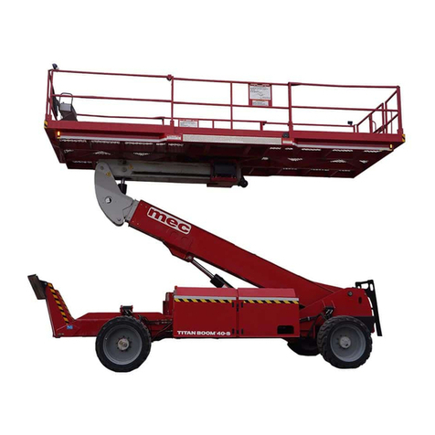
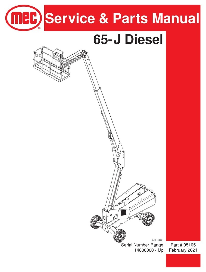
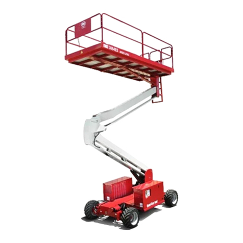
Mec TITAN Boom 40-S Building instructions

SERVICE AND PARTS MANUAL
Titan Boom 40-S
August 2012
ART_3393
Serial Number Range
12400001 - Up Part # 92242

1401 S. Madera Avenue • Kerman, CA 93630 USA
Ph: 1-800-387-4575 • E-mail: info@mecAWP.com
Web: www.mecAWP.com
Aerial Platform Sales Corp.
Revision History
Original Release Date: March 2011
Date Reason for Update
06/2011 New Release
08/2011 1st Revision

“Titan Boom 40-S” Service and Parts Manual August 2012
Page i
Service Table of Contents
Introduction I Page
Machine Specifications - Titan Boom 40-S . . . . . . . . . . . . . . . . . . . . . . . . . . . . . . . . . . . . . . .II
MEC Operator Policy . . . . . . . . . . . . . . . . . . . . . . . . . . . . . . . . . . . . . . . . . . . . . . . . . . . . . . III
Safety Symbols . . . . . . . . . . . . . . . . . . . . . . . . . . . . . . . . . . . . . . . . . . . . . . . . . . . . . . . . . . . IV
General Safety Tips . . . . . . . . . . . . . . . . . . . . . . . . . . . . . . . . . . . . . . . . . . . . . . . . . . . . . . . V
Electrical System . . . . . . . . . . . . . . . . . . . . . . . . . . . . . . . . . . . . . . . . . . . . . . . . . . . . . . . . VII
Total System . . . . . . . . . . . . . . . . . . . . . . . . . . . . . . . . . . . . . . . . . . . . . . . . . . . . . . . . . . . . VII
Primary Machine Components . . . . . . . . . . . . . . . . . . . . . . . . . . . . . . . . . . . . . . . . . . . . . . VIII
Emergency Systems and Procedures . . . . . . . . . . . . . . . . . . . . . . . . . . . . . . . . . . . . . . . . . . X
Emergency Lowering . . . . . . . . . . . . . . . . . . . . . . . . . . . . . . . . . . . . . . . . . . . . . . . . . . . . . . XI
Free-wheel configuration for Winching or Towing . . . . . . . . . . . . . . . . . . . . . . . . . . . . . . . . XII
Lift and Support the Machine . . . . . . . . . . . . . . . . . . . . . . . . . . . . . . . . . . . . . . . . . . . . . . . XIII
Transporting the Machine . . . . . . . . . . . . . . . . . . . . . . . . . . . . . . . . . . . . . . . . . . . . . . . . . .XIV
Safety Information . . . . . . . . . . . . . . . . . . . . . . . . . . . . . . . . . . . . . . . . . . . . . . . . . . . . . . . .XIV
Section 1: Hydraulic System Page
Hydraulic System – General . . . . . . . . . . . . . . . . . . . . . . . . . . . . . . . . . . . . . . . . . . . . . . . . 1-4
Hydraulic Roadmap . . . . . . . . . . . . . . . . . . . . . . . . . . . . . . . . . . . . . . . . . . . . . . . . . . . . . . 1-5
Hydraulic Fluid . . . . . . . . . . . . . . . . . . . . . . . . . . . . . . . . . . . . . . . . . . . . . . . . . . . . . . . . . . 1-7
Handling Precautions . . . . . . . . . . . . . . . . . . . . . . . . . . . . . . . . . . . . . . . . . . . . . . . . . . . . . 1-7
Fluid Recommendations . . . . . . . . . . . . . . . . . . . . . . . . . . . . . . . . . . . . . . . . . . . . . . . . . . . 1-7
System Flushing Procedure . . . . . . . . . . . . . . . . . . . . . . . . . . . . . . . . . . . . . . . . . . . . . . . . 1-7
Hydraulic Fluid Reservoir . . . . . . . . . . . . . . . . . . . . . . . . . . . . . . . . . . . . . . . . . . . . . . . . . . 1-8
Hydraulic Filters . . . . . . . . . . . . . . . . . . . . . . . . . . . . . . . . . . . . . . . . . . . . . . . . . . . . . . . . . 1-8
Hydraulic Pumps . . . . . . . . . . . . . . . . . . . . . . . . . . . . . . . . . . . . . . . . . . . . . . . . . . . . . . . . .1-9
Drive Pump . . . . . . . . . . . . . . . . . . . . . . . . . . . . . . . . . . . . . . . . . . . . . . . . . . . . . . . . . . . . 1-10
Functions Pump . . . . . . . . . . . . . . . . . . . . . . . . . . . . . . . . . . . . . . . . . . . . . . . . . . . . . . . . 1-12
Hydraulic Manifolds . . . . . . . . . . . . . . . . . . . . . . . . . . . . . . . . . . . . . . . . . . . . . . . . . . . . . . 1-13
Hydraulic Pressure Adjustment . . . . . . . . . . . . . . . . . . . . . . . . . . . . . . . . . . . . . . . . . . . . . 1-20
Adjusting Relief Valves . . . . . . . . . . . . . . . . . . . . . . . . . . . . . . . . . . . . . . . . . . . . . . . . . . . 1-21
Adjustments . . . . . . . . . . . . . . . . . . . . . . . . . . . . . . . . . . . . . . . . . . . . . . . . . . . . . . . . . . . 1-22
Drive Pump . . . . . . . . . . . . . . . . . . . . . . . . . . . . . . . . . . . . . . . . . . . . . . . . . . . . . . . . . . . . 1-24
Drive Pump Adjustments . . . . . . . . . . . . . . . . . . . . . . . . . . . . . . . . . . . . . . . . . . . . . . . . . 1-24
Drive Pump/Drive Manifold Connections . . . . . . . . . . . . . . . . . . . . . . . . . . . . . . . . . . . . . 1-27
Suction & Case Drain Connections . . . . . . . . . . . . . . . . . . . . . . . . . . . . . . . . . . . . . . . . . . 1-28
Drive Pump/Function Manifold Connections . . . . . . . . . . . . . . . . . . . . . . . . . . . . . . . . . . . 1-29
Charge Filter Circuit . . . . . . . . . . . . . . . . . . . . . . . . . . . . . . . . . . . . . . . . . . . . . . . . . . . . .1-30
Functions Pump/Functions Manifold Connections . . . . . . . . . . . . . . . . . . . . . . . . . . . . . . 1-31
Hydraulic Functions . . . . . . . . . . . . . . . . . . . . . . . . . . . . . . . . . . . . . . . . . . . . . . . . . . . . . 1-32
Drive Function . . . . . . . . . . . . . . . . . . . . . . . . . . . . . . . . . . . . . . . . . . . . . . . . . . . . . . . . . . 1-32
Wheel Motor Startup Procedure . . . . . . . . . . . . . . . . . . . . . . . . . . . . . . . . . . . . . . . . . . . . 1-33
High Speed Function . . . . . . . . . . . . . . . . . . . . . . . . . . . . . . . . . . . . . . . . . . . . . . . . . . . . 1-35
Brake Release Function . . . . . . . . . . . . . . . . . . . . . . . . . . . . . . . . . . . . . . . . . . . . . . . . . . 1-36
Drive Case Drain Function . . . . . . . . . . . . . . . . . . . . . . . . . . . . . . . . . . . . . . . . . . . . . . . . 1-37
Axle Lock Function . . . . . . . . . . . . . . . . . . . . . . . . . . . . . . . . . . . . . . . . . . . . . . . . . . . . . . 1-38
Frame Level Function . . . . . . . . . . . . . . . . . . . . . . . . . . . . . . . . . . . . . . . . . . . . . . . . . . . . 1-39
Steering Function . . . . . . . . . . . . . . . . . . . . . . . . . . . . . . . . . . . . . . . . . . . . . . . . . . . . . . .1-40

“Titan Boom 40-S” Service and Parts ManualAugust 2012
Page ii
Service Table of Contents
Stabilizer System . . . . . . . . . . . . . . . . . . . . . . . . . . . . . . . . . . . . . . . . . . . . . . . . . . . . . . . 1-41
Boom Lift System . . . . . . . . . . . . . . . . . . . . . . . . . . . . . . . . . . . . . . . . . . . . . . . . . . . . . . . 1-42
Boom Extend System . . . . . . . . . . . . . . . . . . . . . . . . . . . . . . . . . . . . . . . . . . . . . . . . . . . . 1-43
Auxiliary Manifold Supply . . . . . . . . . . . . . . . . . . . . . . . . . . . . . . . . . . . . . . . . . . . . . . . . . 1-44
Platform Level Function . . . . . . . . . . . . . . . . . . . . . . . . . . . . . . . . . . . . . . . . . . . . . . . . . . 1-45
Platform Rotate Function . . . . . . . . . . . . . . . . . . . . . . . . . . . . . . . . . . . . . . . . . . . . . . . . . 1-46
Platform Slide Function . . . . . . . . . . . . . . . . . . . . . . . . . . . . . . . . . . . . . . . . . . . . . . . . . . 1-47
Emergency Power Function . . . . . . . . . . . . . . . . . . . . . . . . . . . . . . . . . . . . . . . . . . . . . . . 1-48
Generator Option . . . . . . . . . . . . . . . . . . . . . . . . . . . . . . . . . . . . . . . . . . . . . . . . . . . . . . . 1-49
General Cylinder Repair . . . . . . . . . . . . . . . . . . . . . . . . . . . . . . . . . . . . . . . . . . . . . . . . . . 1-50
Removal . . . . . . . . . . . . . . . . . . . . . . . . . . . . . . . . . . . . . . . . . . . . . . . . . . . . . . . . . . . . . . 1-50
Preparation . . . . . . . . . . . . . . . . . . . . . . . . . . . . . . . . . . . . . . . . . . . . . . . . . . . . . . . . . . . . 1-51
Cylinder Disassembly . . . . . . . . . . . . . . . . . . . . . . . . . . . . . . . . . . . . . . . . . . . . . . . . . . . . 1-51
Cylinder Assembly . . . . . . . . . . . . . . . . . . . . . . . . . . . . . . . . . . . . . . . . . . . . . . . . . . . . . . 1-52
Extend Cylinder Disassembly & Assembly . . . . . . . . . . . . . . . . . . . . . . . . . . . . . . . . . . . 1-53
Section 2: Electrical System Page
Electrical System – General . . . . . . . . . . . . . . . . . . . . . . . . . . . . . . . . . . . . . . . . . . . . . . . . 2-3
Batteries . . . . . . . . . . . . . . . . . . . . . . . . . . . . . . . . . . . . . . . . . . . . . . . . . . . . . . . . . . . . . . . 2-5
Battery Maintenance (in storage) . . . . . . . . . . . . . . . . . . . . . . . . . . . . . . . . . . . . . . . . . . . . 2-5
Battery Replacement . . . . . . . . . . . . . . . . . . . . . . . . . . . . . . . . . . . . . . . . . . . . . . . . . . . . . 2-7
Controls . . . . . . . . . . . . . . . . . . . . . . . . . . . . . . . . . . . . . . . . . . . . . . . . . . . . . . . . . . . . . . . 2-8
Lower Controls . . . . . . . . . . . . . . . . . . . . . . . . . . . . . . . . . . . . . . . . . . . . . . . . . . . . . . . . . . 2-8
Platform Controls . . . . . . . . . . . . . . . . . . . . . . . . . . . . . . . . . . . . . . . . . . . . . . . . . . . . . . . 2-10
Sensors, Relays & Alarms . . . . . . . . . . . . . . . . . . . . . . . . . . . . . . . . . . . . . . . . . . . . . . . . 2-12
Sensors . . . . . . . . . . . . . . . . . . . . . . . . . . . . . . . . . . . . . . . . . . . . . . . . . . . . . . . . . . . . . . 2-12
Relays . . . . . . . . . . . . . . . . . . . . . . . . . . . . . . . . . . . . . . . . . . . . . . . . . . . . . . . . . . . . . . . 2-16
Alarms . . . . . . . . . . . . . . . . . . . . . . . . . . . . . . . . . . . . . . . . . . . . . . . . . . . . . . . . . . . . . . . 2-17
Deutsch Connectors . . . . . . . . . . . . . . . . . . . . . . . . . . . . . . . . . . . . . . . . . . . . . . . . . . . . . 2-18
Continuity Checks . . . . . . . . . . . . . . . . . . . . . . . . . . . . . . . . . . . . . . . . . . . . . . . . . . . . . . 2-19
Control System . . . . . . . . . . . . . . . . . . . . . . . . . . . . . . . . . . . . . . . . . . . . . . . . . . . . . . . . . 2-22
Components & Locations . . . . . . . . . . . . . . . . . . . . . . . . . . . . . . . . . . . . . . . . . . . . . . . . . 2-22
GP400 Calibration . . . . . . . . . . . . . . . . . . . . . . . . . . . . . . . . . . . . . . . . . . . . . . . . . . . . . . 2-23
Calibration Problems . . . . . . . . . . . . . . . . . . . . . . . . . . . . . . . . . . . . . . . . . . . .2-28
Failure Messages . . . . . . . . . . . . . . . . . . . . . . . . . . . . . . . . . . . . . . . . . . . . . . . . . . . . . . . 2-28
Information Messages . . . . . . . . . . . . . . . . . . . . . . . . . . . . . . . . . . . . . . . . . . . . . . . . . . . 2-32
Section 3: Mechanical Components Page
Mechanical Components . . . . . . . . . . . . . . . . . . . . . . . . . . . . . . . . . . . . . . . . . . . . . . . . . . 3-3
Base . . . . . . . . . . . . . . . . . . . . . . . . . . . . . . . . . . . . . . . . . . . . . . . . . . . . . . . . . . . . . . . . . . 3-3
Tires & Wheels . . . . . . . . . . . . . . . . . . . . . . . . . . . . . . . . . . . . . . . . . . . . . . . . . . . . . . . . . . 3-3
Drive Motors & Gear Hubs . . . . . . . . . . . . . . . . . . . . . . . . . . . . . . . . . . . . . . . . . . . . . . . . . 3-4
Hoses & Cables . . . . . . . . . . . . . . . . . . . . . . . . . . . . . . . . . . . . . . . . . . . . . . . . . . . . . . . . . 3-9
Steer Cylinders . . . . . . . . . . . . . . . . . . . . . . . . . . . . . . . . . . . . . . . . . . . . . . . . . . . . . . . . . 3-10
Axle Cylinders . . . . . . . . . . . . . . . . . . . . . . . . . . . . . . . . . . . . . . . . . . . . . . . . . . . . . . . . . 3-11
Stabilizer Cylinders . . . . . . . . . . . . . . . . . . . . . . . . . . . . . . . . . . . . . . . . . . . . . . . . . . . . . 3-13

“Titan Boom 40-S” Service and Parts Manual August 2012
Page iii
Service Table of Contents
Platform Removal & Installation . . . . . . . . . . . . . . . . . . . . . . . . . . . . . . . . . . . . . . . . . . . . 3-15
Platform Rotate Drive Unit . . . . . . . . . . . . . . . . . . . . . . . . . . . . . . . . . . . . . . . . . . . . . . . . 3-17
Platform Carriage . . . . . . . . . . . . . . . . . . . . . . . . . . . . . . . . . . . . . . . . . . . . . . . . . . . . . . .3-18
Platform Beam & Platform Level Cylinder . . . . . . . . . . . . . . . . . . . . . . . . . . . . . . . . . . . . . 3-22
Extend Cylinder . . . . . . . . . . . . . . . . . . . . . . . . . . . . . . . . . . . . . . . . . . . . . . . . . . . . . . . . .3-23
Boom . . . . . . . . . . . . . . . . . . . . . . . . . . . . . . . . . . . . . . . . . . . . . . . . . . . . . . . . . . . . . . . . . 3-27
Boom Lift Cylinder . . . . . . . . . . . . . . . . . . . . . . . . . . . . . . . . . . . . . . . . . . . . . . . . . . . . . . .3-32
Engine Maintenance . . . . . . . . . . . . . . . . . . . . . . . . . . . . . . . . . . . . . . . . . . . . . . . . . . . . . 3-37
Oil and Oil Filter . . . . . . . . . . . . . . . . . . . . . . . . . . . . . . . . . . . . . . . . . . . . . . . . . . . . . . . . 3-37
Air Filter Element . . . . . . . . . . . . . . . . . . . . . . . . . . . . . . . . . . . . . . . . . . . . . . . . . . . . . . .3-37
Fuel Filter . . . . . . . . . . . . . . . . . . . . . . . . . . . . . . . . . . . . . . . . . . . . . . . . . . . . . . . . . . . . . 3-38
Throttle Adjustment . . . . . . . . . . . . . . . . . . . . . . . . . . . . . . . . . . . . . . . . . . . . . . . . . . . . . . 3-39
Lubrication Points . . . . . . . . . . . . . . . . . . . . . . . . . . . . . . . . . . . . . . . . . . . . . . . . . . . . . . .3-39
Section 4: Troubleshooting Page
General Troubleshooting Tips . . . . . . . . . . . . . . . . . . . . . . . . . . . . . . . . . . . . . . . . . . . . . . . 4-3
Electrical System Troubleshooting . . . . . . . . . . . . . . . . . . . . . . . . . . . . . . . . . . . . . . . . . . . 4-4
GP400 Module . . . . . . . . . . . . . . . . . . . . . . . . . . . . . . . . . . . . . . . . . . . . . . . . . . . . . . . . . .4-5
GP440 Module . . . . . . . . . . . . . . . . . . . . . . . . . . . . . . . . . . . . . . . . . . . . . . . . . . . . . . . . . .4-7
Matrix Module . . . . . . . . . . . . . . . . . . . . . . . . . . . . . . . . . . . . . . . . . . . . . . . . . . . . . . . . . . . 4-8
Terminal Block Module (TBM) . . . . . . . . . . . . . . . . . . . . . . . . . . . . . . . . . . . . . . . . . . . . . . 4-8
EZ-Cal Scan Tools . . . . . . . . . . . . . . . . . . . . . . . . . . . . . . . . . . . . . . . . . . . . . . . . . . . . . . .4-9
Onboard EZ-Cal -- Lower Controls Box . . . . . . . . . . . . . . . . . . . . . . . . . . . . . . . . . . . . . . . 4-9
Handheld EZ-Cal -- Upper Controls Box . . . . . . . . . . . . . . . . . . . . . . . . . . . . . . . . . . . . . . 4-10
EZ-Cal Adjustment . . . . . . . . . . . . . . . . . . . . . . . . . . . . . . . . . . . . . . . . . . . . . . . . . . . . . . 4-16
EZ-Cal Setup . . . . . . . . . . . . . . . . . . . . . . . . . . . . . . . . . . . . . . . . . . . . . . . . . . . . . . . . . .4-19
EZ-Cal Diagnostics . . . . . . . . . . . . . . . . . . . . . . . . . . . . . . . . . . . . . . . . . . . . . . . . . . . . . . 4-20
EZ-Cal Messages . . . . . . . . . . . . . . . . . . . . . . . . . . . . . . . . . . . . . . . . . . . . . . . . . . . . . . . 4-24
Troubleshooting Chart . . . . . . . . . . . . . . . . . . . . . . . . . . . . . . . . . . . . . . . . . . . . . . . . . . . 4-29
Section 5: Schematics Page
Hydraulic Schematics . . . . . . . . . . . . . . . . . . . . . . . . . . . . . . . . . . . . . . . . . . . . . . . . . . . . . 5-3
Electrical Schematics - Standard Machine . . . . . . . . . . . . . . . . . . . . . . . . . . . . . . . . . . . . . 5-9
Electrical Schematics - Optional Overload Sensing System . . . . . . . . . . . . . . . . . . . . . . . 5-13

“Titan Boom 40-S” Service and Parts ManualAugust 2012
Page iv
Service Table of Contents

“Titan Boom 40-S” Service and Parts Manual June 2011
Page I
INTRODUCTION
This manual consists of Service and Illustrated Parts sections.
The Service Section of this manual is designed to provide you, the customer, with the instructions
needed to properly maintain the MEC self-propelled aerial work platform. When used in conjunc-
tion with the Illustrated Parts Section and the Operators Manual (provided separately), this manual
will assist you in making necessary adjustments and repairs, and identifying and ordering the
correct replacement parts.
All parts represented here are manufactured and supplied in accordance with MEC quality
standards.
We recommend that you use genuine MEC parts to ensure proper operation and reliable
performance.
To obtain maximum benefits from your MEC Aerial Work Platform, always follow the proper
operating and maintenance procedures. Only trained, authorized personnel should be allowed to
operate or service this machine. Service personnel should read and study the Operator’s, Service
and Parts Manuals in order to gain a thorough understanding of the unit prior to making any
repairs.
C
ONTENTS
P
AGE
Machine Specifications - Titan Boom 40-S . . . . . . . . . . . . . . . . . . . . . . . . . . . . . II
MEC Operator Policy . . . . . . . . . . . . . . . . . . . . . . . . . . . . . . . . . . . . . . . . . . . . . .III
Safety Symbols . . . . . . . . . . . . . . . . . . . . . . . . . . . . . . . . . . . . . . . . . . . . . . . . . IV
General Safety Tips . . . . . . . . . . . . . . . . . . . . . . . . . . . . . . . . . . . . . . . . . . . . . . . V
Electrical System . . . . . . . . . . . . . . . . . . . . . . . . . . . . . . . . . . . . . . . . . . . . . . . . VII
Total System . . . . . . . . . . . . . . . . . . . . . . . . . . . . . . . . . . . . . . . . . . . . . . . . . . . VII
Primary Machine Components . . . . . . . . . . . . . . . . . . . . . . . . . . . . . . . . . . . . . VIII
Emergency Systems and Procedures . . . . . . . . . . . . . . . . . . . . . . . . . . . . . . . . . X
Emergency Lowering . . . . . . . . . . . . . . . . . . . . . . . . . . . . . . . . . . . . . . . . . . . . . XI
Free-wheel configuration for Winching or Towing . . . . . . . . . . . . . . . . . . . . . . . XII
Lift and Support the Machine . . . . . . . . . . . . . . . . . . . . . . . . . . . . . . . . . . . . . . XIII
Transporting the Machine . . . . . . . . . . . . . . . . . . . . . . . . . . . . . . . . . . . . . . . . XIV
Safety Information . . . . . . . . . . . . . . . . . . . . . . . . . . . . . . . . . . . . . . . . . . . . . . XIV
F
IGURES
P
AGE
Maintenance Chick Stowage . . . . . . . . . . . . . . . . . . . . . . . . . . . . . . . . . . . . . . . VI
Maintenance Chock Installation . . . . . . . . . . . . . . . . . . . . . . . . . . . . . . . . . . . . . VI
Component Locations . . . . . . . . . . . . . . . . . . . . . . . . . . . . . . . . . . . . . . . . . . . VIII
Emergency Stop Switch . . . . . . . . . . . . . . . . . . . . . . . . . . . . . . . . . . . . . . . . . . . . X
Emergency Power Switch . . . . . . . . . . . . . . . . . . . . . . . . . . . . . . . . . . . . . . . . . XI
Brake Release . . . . . . . . . . . . . . . . . . . . . . . . . . . . . . . . . . . . . . . . . . . . . . . . . . XII
Loading the Machine . . . . . . . . . . . . . . . . . . . . . . . . . . . . . . . . . . . . . . . . . . . . XIV

“Titan Boom 40-S” Service and Parts ManualJune 2011
Page II
M
ACHINE
S
PECIFICATIONS
- T
ITAN
B
OOM
40-S
TITAN Boom™ 40-S
Working Height* 46 ft 14.2 m
Platform Height 40 ft 12.2 m
Maximum Drive Height 30 ft 9.1 m
Maximum Forward Reach w/ Stabilizers 26 ft 6 in 8 m
Machine Weight** (Unloaded) 24400 lb 11065 kg
Lift Capacity Total 4000 lb 1810 kg
Load Zone 3000 lb 1360 kg
Personnel & Tools Evenly Distributed 1000 lb 450 kg
Maximum Occupants 4
Stowed Height Rails Up 118 in 3 m
Rails Folded Down 84 in 2.13 m
Overall Length 22 ft 6 in 6.9 m
Overall Width 96 in 2.44 m
Wheel Base 152 in 3.85 m
Wheel Track 82 in 2.08 m
Platform Dimensions Length 22 ft 6.7 m
Platform Width 90 in 2.28 m
Loading Height 72 in 1.83 m
Turning Radius,
(4 Wheel Steer)
Inside 8 ft 2.4 m
Outside 19 ft 5.8 m
Ground Clearance 18 in 46 cm
Lift/Lower Speeds 50 sec/ 50 sec
Extend/Retract Speeds 30 sec/ 30 sec
Platform Translation Speed 15 sec
Drive Speed
(Proportional)
Stowed 0-4 mph 0-6.4 km/h
Raised or extended 0-.5 mph 0-.8 km/h
Gradeability Stowed, downhill 40%/22°
Stowed, uphill 40%/22°
Approach Angle 38%/21°
Breakover Angle 40%/22° Engine Kubota V2403-T
Platform Rotation 180° (+90°, -90°) Fuel Type Diesel
Frame Level 10° each side Fuel Capacity 32 gal 120 liter
Maximum Operating Wind Speed 28 mph 12.5 m/sec
(45 km/h)
Alternator 40 amp
Ground Pressure/Wheel (Maximum) 160 psi 11.2 kg/cm2Batteries Two 1000 CCA 12V
Group 31
Maximum Wheel Load 9600 lbs 4350 kg Noise Level 86 dB(A) @ work station
Tire Size 37 in. od .94 m od Control System 12V DC
Wheel Lug Nut Torque 150 ft/lb 203 Nm Brakes 4 wheel multi disc
Hydraulic Pressure Drive System 4350 psi 300 bar Maximum
Vibration
does not exceed
2.5 m/sec2at operator’s
position
Main System 3000 psi 207 bar
Hydraulic Fluid Capacity 40 gal 150 liter Ambient Operating
Range
-40° F (-40° C) minimum;
122° F (50° C) maximum
*Working Height adds 6 feet (2 m) to platform height.
**Weight may increase with certain options or country standards.

“Titan Boom 40-S” Service and Parts Manual June 2011
Page III
MEC O
PERATOR
P
OLICY
NOTE: The best method to protect yourself and others from injury or death is to use common sense. If you are unsure
of any operation, don’t start until you are satisfied that it is safe to proceed and have discussed the situation with
your supervisor.
Service personnel and machine operators must understand and comply with all warn-
ings and instructional decals on the body of the machine, at the ground controls, and
platform control console.
MODIFICATIONS OF THIS MACHINE FROM THE ORIGINAL DESIGN AND
SPECIFICATIONS WITHOUT WRITTEN PERMISSION FROM MEC ARE STRICTLY
FORBIDDEN. A MODIFICATION MAY COMPROMISE THE SAFETY OF THE
MACHINE, SUBJECTING OPERATOR(S) TO SERIOUS INJURY OR DEATH.
MEC’s policies and procedures demonstrate our commitment to Quality and our relent-
less ongoing efforts towards Continuous Improvement, due to which product specifica-
tions are subject to change without notice.
Any procedures not found within this manual must be evaluated by the individual to
assure oneself that they are “proper and safe.”
Your MEC Aerial Work Platform has been designed, built, and tested to provide many
years of safe, dependable service. Only trained, authorized personnel should be
allowed to operate or service the machine.
MEC, As Manufacturer, Has No Direct Control Over Machine Application And Opera-
tion. Proper Safety Practices Are The Responsibility Of The User And All Operating
Personnel.
If there is any question regarding application and/or operation contact:
MEC Aerial Work Platform
1401 S. Madera Avenue
Kerman, CA 93630 USA
Ph: 1-800-387-4575
www.mecAWP.com

“Titan Boom 40-S” Service and Parts ManualJune 2011
Page IV
S
AFETY
S
YMBOLS
To help you recognize important safety information, we have identified warnings and instructions
that directly impact on safety with the following signals:
“DANGER” INDICATES AN IMMINENTLY HAZARDOUS SITUATION WHICH, IF
NOT AVOIDED, WILL RESULT IN DEATH OR SERIOUS INJURY.
THIS SIGNAL WORD IS LIMITED TO THE MOST EXTREME SITUATIONS.
“WARNING” INDICATES A POTENTIALLY HAZARDOUS SITUATION WHICH, IF
NOT AVOIDED, COULD RESULT IN DEATH OR SERIOUS INJURY.
“CAUTION” indicates a potentially hazardous situation which, if not avoided, may
result in minor or moderate injury. It may also be used to alert against unsafe
practices.
“Caution” without alert symbol indicates a situation which, if not avoided, may
result in property damage.

“Titan Boom 40-S” Service and Parts Manual June 2011
Page V
G
ENERAL
S
AFETY
T
IPS
Regular inspection and conscientious maintenance is the key to efficient, economical
operation of your aerial work platform. It will help to assure that your equipment will per-
form satisfactorily with a minimum of service and repair.
The actual operating environment of the machine governs the inspection schedule. Cor-
rect lubrication is an essential part of the preventative maintenance to minimize wear on
working parts and ensure against premature failure. By maintaining correct lubrication, the
possibility of mechanical failure and resulting downtime is reduced to a minimum.
M
AINTENANCE
T
IPS
• Never leave hydraulic components or hoses open. They must be protected from contamina-
tion (including rain) at all times.
• Never open a hydraulic system when there are contaminants in the air.
• Always clean the surrounding area before opening hydraulic systems.
• Use only recommended lubricants. Improper lubricants or incompatible lubricants may be as
harmful as no lubrication.
• Watch for makeshift “fixes” which can jeopardize safety as well as lead to more costly repair.

“Titan Boom 40-S” Service and Parts ManualJune 2011
Page VI
S
ETTING
T
HE
M
AINTENANCE
C
HOCK
NEVER PERFORM WORK OR INSPECTION ON THE MACHINE WITH THE
PLATFORM ELEVATED WITHOUT FIRST BLOCKING THE BOOM ASSEMBLY
WITH THE MAINTENANCE CHOCK.
THE MAINTENANCE CHOCK IS HEAVY. HOLD IT SECURELY DURING THE
INSTALLATION AND REMOVAL PROCESS.
THE MAINTENANCE CHOCK MAY ROTATE AROUND THE CYLINDER ROD
DURING MACHINE MOVEMENT AND MAY FALL IF IT IS NOT HELD SECURELY
IN PLACE DURING INSTALLATION AND REMOVAL.
The Maintenance Chock fits over the lift cylinder rod, between the rod end and the end
of the cylinder barrel.
I
NSTALLATION
Figure 1-1: Maintenance Chock Stowage
• Remove the Maintenance Chock
from the tool storage compart-
ment of the Engine Module.
• Using the Boom Lift/Lower func-
tion, raise the platform to
approximately 13 feet (4 m).
• Place the Maintenance Chock
over the cylinder rod above the
cylinder barrel.
• Using the Boom Lift/Lower func-
tion, slowly lower the boom until
the Maintenance Chock is secure between the cylinder rod end and the cylinder barrel.
R
EMOVAL
• Using the Boom Lift/Lower function, raise the platform to approximately 13 feet
(4 m) until the Maintenance Chock moves freely.
• Remove the Maintenance Chock from the cylinder rod.
• Store the Maintenance Chock in the tool storage compartment of the Engine Module.
Figure 1-2: Maintenance Chock Installation
ART_3776
Maintenance
Chock stowed in
compartment
beside engine
ART_3475
Proper Placement
Of Maintenance
Choc
k
Maintenance
Chock
Cylinder
Rod

“Titan Boom 40-S” Service and Parts Manual June 2011
Page VII
H
YDRAULIC
S
YSTEM
HYDRAULIC FLUID UNDER PRESSURE CAN PENETRATE AND BURN SKIN,
DAMAGE EYES, AND MAY CAUSE SERIOUS INJURY, BLINDNESS, AND EVEN
DEATH.
CORRECT LEAKS IMMEDIATELY.
Hydraulic fluid leaks under pressure may not always be visible. Check for pin hole
leaks with a piece of cardboard, not your hand.
E
LECTRICAL
S
YSTEM
To prevent damage to battery and/or electrical system:
• Always disconnect the negative battery cable first.
• Always connect the positive battery cable first.
When the negative cable is installed, a spark will occur if contact is made between the
positive side of the battery and a metal surface on the machine. This can cause electrical
system damage, battery explosion, and personal injury.
T
OTAL
S
YSTEM
ENGINE COOLANT LEVEL MUST BE CHECKED ONLY AFTER ENGINE HAS
COOLED. IF RADIATOR CAP IS REMOVED WHILE THE COOLANT IS AT NORMAL
OPERATING TEMPERATURE, PRESSURE WITHIN THE COOLANT SYSTEM WILL
FORCE HOT LIQUID OUT THROUGH THE FILLER OPENING AND MAY CAUSE
SEVERE SCALDING.
Failure to perform preventive maintenance at recommended intervals may result
in the unit being operated with a defect that could result in injury or death of the
operator.
Immediately report to your supervisor any defect or malfunction. Any defect
shall be repaired prior to continued use of the aerial work platform.
Inspection and maintenance should be performed by qualified personnel
familiar with the equipment.

“Titan Boom 40-S” Service and Parts ManualJune 2011
Page VIII
P
RIMARY
M
ACHINE
C
OMPONENTS
Figure 1-3: Component Locations
ART_3389
ControlsModule
Platform
Controls
Platform
Boom Lift
Cylinder
Chassis
Battery
Disconnect
Switch
Stabilizer
Maintenance Chock
Storage Compartment
Function Enable
Foot Switch
Boom
Load Zone
Material
Loading
Gates*
Personnel
Entry Gate
Material Load
Securing D-Rings
Material Load
Securing D-Ring
Material Load
Securing D-Ring
Fuel
Tank
Hydraulic
Tank
Base
Controls
Hydraulic
Manifold
Entry Ladder
Engine Module
*For Material Loading Only.
Not For Personnel.

“Titan Boom 40-S” Service and Parts Manual June 2011
Page IX
T
ORQUE
S
PECIFICATIONS
F
ASTENERS
Use the following values to apply torque unless a specific torque value is called out for
the part being used.
H
YDRAULIC
C
OMPONENTS
T
ORQUE
T
ABLE
NOTE: Always lubricate threads with clean hydraulic fluid prior to installation.
Use the following values to torque hydraulic components when a specific value is not
available. Always check for torque values in the following places before relying on the
Hydraulic Components Torque Table:
• parts drawings and service instructions in this manual.
• packaging and instruction sheets provided with new parts.
• instruction manuals provided by the manufacturer of the component being serviced.
SAE GRADE
TORQUE
FT. LBS
MIN MAX
TORQUE
Nm
MIN MAX
FT. LBS
MIN MAX
Nm TORQUE
FT. LBS TORQUE
Nm FT. LBS Nm
MIN MAX MIN MAX MIN MAX MIN MAX MIN MAX
CAP SCREW
SIZE
- millimeters-
CAP SCREW
SIZE
- inches -
58
METRIC GRADE
8.8 10.9
8.8 10.9
1/4 - 20 6.25
8
14
17.5
26
31
41
51
65
76
95
111
126
152
238
274
350
407
537
670
7.25
9
15
19
28
34
45
55
72
84
105
123
139
168
262
302
386
448
592
740
8.5
11
19
23
35
42
55.5
69
88
103
129
150
171
206
322
371
474
551
728
908
10
12
20
26
38
46
61
74.5
97.5
114
142
167
188
228
255
409
523
607
802
1003
8.25
10.5
18.5
23
35
41
55
68
86
102
127
148
168
203
318
365
466
543
716
894
9.5
12
20
25
37
45
60
75
96
112
140
164
185
224
350
402
515
597
790
987
11
14
25
31
47.5
55.5
74.5
92
116
138
172
200
228
275
431
495
631
736
970
1211
13
16
27
34
50
61
81
102
130
152
190
222
251
304
474
544
698
809
1070
1137
M6 X 1.00
M8 X 1.25
M10 X 1.50
M12 X 1.75
M14 X 2.00
M16 X 2.50
M18 X 2.50
M20 X 2.50
M22 X 2.50
M24 X 3.00
M27 X 3.00
M3 X 3.00
6
16
29
52
85
130
172
247
332
423
637
872
8
20
35
62
103
158
210
301
404
517
779
1066
8
21.5
39
70
115
176
233
335
450
573
863
1181
11
27
47
84
139
214
284
408
547
700
1055
1444
9
23
42
75
120
176
240
343
472
599
898
1224
11
27
52
91
146
216
294
426
576
732
1098
1496
12
31
57
102
163
238
325
465
639
812
1217
1658
15
36.5
70
123
198
293
398
577
780
992
1488
2027
1/4 - 28
5/16 - 18
5/16 - 24
3/8 - 16
3/8 - 24
7/16 - 14
7/16 - 20
1/2 - 13
1/2 - 20
9/16 - 12
9/16 - 18
5/8 - 11
5/8 - 18
3/4 - 10
3/4 - 16
7/8 - 9
7/8 - 14
1 - 8
1 - 14
Torque valuesapply to fasteneersasreceived
from the supplier, dry or when lubricated with
normal engine oil.
If special graphite grease, molydisulphide
grease, or other extreme pressure lubricants
are used, these torque valuesdo not apply.
AMERICAN STANDARD CAP SCREWS METRIC CAP SCREWS
TYPE: SAE PORT SERIES CARTRIDGE POPPET FITTINGS HOSES
FT. LBS Nm
#4
#6
#8
#10
#12
#16
N/A
N/A
25 - 30
35 - 40
85 - 90
130 - 140
N/A
N/A
31 - 41
47 - 54
115 - 122
176 - 190
FT. LBS Nm
N/A
10 - 20
25 - 30
35 - 40
85 - 90
130 - 140
N/A
14 - 27
34 - 41
47 - 54
115 - 122
176 - 190
FT. LBS Nm
135 - 145
215 - 245
430 - 470
680 - 750
950 - 1050
1300 - 1368
15 - 16
24 - 28
49 - 53
77 - 85
107 - 119
147 - 155

“Titan Boom 40-S” Service and Parts ManualJune 2011
Page X
E
MERGENCY
S
YSTEMS
AND
P
ROCEDURES
IF THE CONTROL SYSTEM FAILS WHILE THE PLATFORM IS ELEVATED, HAVE
AN EXPERIENCED OPERATOR USE THE EMERGENCY LOWERING PROCEDURE
TO SAFELY LOWER THE PLATFORM.
DO NOT ATTEMPT TO CLIMB DOWN ELEVATING ASSEMBLY.
E
MERGENCY
S
TOP
Figure 1-4: Emergency Stop Switch
The machine is equipped with an EMERGENCY STOP switch
on both control panels.
• Press the EMERGENCY STOP switch at any time to stop all machine
functions.
• Turn switch clockwise to reset.
S
ELECTOR
S
WITCH
SET
TO
PLATFORM
• Either switch will stop all machine functions.
• Both switches must be reset or machine will not operate.
S
ELECTOR
S
WITCH
IS
SET
TO
BASE
• The upper controls are locked out.
• The lower controls switch must be reset or the machine will not operate.
• The machine will operate from the lower controls if the upper controls switch is tripped.
ART_3353

“Titan Boom 40-S” Service and Parts Manual June 2011
Page XI
E
MERGENCY
L
OWERING
IF THE CONTROL SYSTEM FAILS WHILE THE PLATFORM IS ELEVATED, USE
THE EMERGENCY LOWERING PROCEDURE TO SAFELY LOWER THE
PLATFORM.
DO NOT CLIMB DOWN THE BOOM ASSEMBLY OR EXIT THE PLATFORM.
The Emergency Lowering System is used to lower the platform in case of power failure.
To lower the platform, activate the Emergency Power Switch to run the Emergency
Down auxiliary hydraulic pump.
This function uses battery power from the auxiliary battery to lower the platform.
• Push and hold the Emergency Power Switch, then use the Boom Extend/Retract function to
retract the boom.
• Continue to hold the Emergency Power Switch, then use the Boom Lift/Lower function to
lower the boom.
NOTE: The Emergency Lowering System overrides the engine function. The engine will shut off when the Emergency
Power Switch is engaged.
The Emergency Power Switch serves as an enable switch. It is not necessary to use the primary function
enable switch.
Figure 1-5: Emergency Power Switch
ART_3525
Base Controls
Platform Controls
Emergency
Lowering Switch
Emergency
Power Switch
Emergency
Power Switch

“Titan Boom 40-S” Service and Parts ManualJune 2011
Page XII
F
REE
-
WHEEL
CONFIGURATION
FOR
W
INCHING
OR
T
OWING
The machine can be winched or moved short distances in case of power failure at
speeds not to exceed 5 MPH (8.05 km/h). Before towing or winching the machine, it is
necessary to release the brake. Reset the brakes after winching or towing.
RUNAWAY HAZARD!
AFTER RELEASING THE BRAKES THERE IS NOTHING TO STOP MACHINE
TRAVEL. MACHINE WILL ROLL FREELY ON SLOPES.
ALWAYS CHOCK THE WHEELS BEFORE MANUALLY RELEASING THE
BRAKES.
Figure 1-6: Brake Release
D
ISENGAGE
B
RAKES
B
EFORE
T
OWING
OR
W
INCHING
• Chock the wheels.
• Remove the Brake Engage Cap and reinstall with the bump
facing inward on all four (4) hubs.
E
NGAGE
B
RAKES
B
EFORE
D
RIVING
• Remove the Brake Engage Cap and reinstall with the bump
facing outward on all four (4) hubs.
DISENGAGED
ENGAGED
ART_2848

“Titan Boom 40-S” Service and Parts Manual June 2011
Page XIII
L
IFT
AND
S
UPPORT
THE
M
ACHINE
DEATH OR SERIOUS PERSONAL INJURY MAY RESULT FROM THE USE OF
SUBSTANDARD LIFTING DEVICES AND/OR JACK STANDS. ENSURE THAT ALL
LIFTING DEVICES AND JACK STANDS ARE OF ADEQUATE CAPACITY AND IN
GOOD WORKING CONDITION BEFORE USE.
The following are needed to safely lift and support the machine;
• a jack with a lifting capacity of seven (7) tons or more.
• jack stands with a rating of seven (7) tons or more.
T
O
RAISE
THE
MACHINE
1. Move machine to a firm level surface capable of supporting the weight of the
machine.
2. Chock the tires on the end of machine opposite the end to be raised.
3. If wheel is to be removed, break loose but do not remove lug nuts before raising the
machine.
4. Position a jack at the end of the machine to be lifted, under a solid lifting point in the
center of the frame.
5. Raise the machine and place two (2) suitable jack stands under solid support points
at the outer ends of the frame.
6. Lower the machine to rest on the jack stands and inspect for stability.
T
O
LOWER
THE
MACHINE
1. Tighten lug nuts to hold the wheel snug to the hub. Do not torque the lug nuts at this
time.
2. Raise machine slightly and remove jack stands.
3. Lower the machine and remove the jack.
4. Tighten lug nuts to proper torque (refer to machine specifications).
5. Remove chocks.

“Titan Boom 40-S” Service and Parts ManualJune 2011
Page XIV
T
RANSPORTING
THE
M
ACHINE
S
AFETY
I
NFORMATION
THIS INFORMATION IS PROVIDED FOR REFERENCE AND DOES NOT
SUPERSEDE ANY GOVERNMENT OR COMPANY POLICY REGARDING THE
LOADING, TRANSPORT OR LIFTING OF MEC MACHINERY.
DRIVERS ARE RESPONSIBLE FOR LOADING AND SECURING MACHINES,
AND SHOULD BE PROPERLY TRAINED AND AUTHORIZED TO OPERATE
MEC MACHINERY.
DRIVERS ARE ALSO RESPONSIBLE FOR SELECTING THE CORRECT AND
APPROPRIATE TRAILER ACCORDING TO GOVERNMENT REGULATIONS
AND COMPANY POLICY.
DRIVERS MUST ENSURE THAT THE VEHICLE AND CHAINS ARE STRONG
ENOUGH TO HOLD THE WEIGHT OF THE MACHINE (SEE THE SERIAL
NUMBER PLATE FOR MACHINE WEIGHT).
D
RIVING
OR
W
INCHING
ONTO
OR
OFF
OF
A
T
RANSPORT
V
EHICLE
MEC DOES NOT RECOMMEND UNASSISTED LOADING OR UNLOADING.
ALWAYS ATTACH THE MACHINE TO A WINCH WHEN LOADING OR UNLOADING
FROM A TRUCK OR TRAILER BY DRIVING.
Refer to the Operator’s Manual for loading, unloading, driving and operating instruc-
tions.
Figure 1-7: Loading the Machine
Winch
Stabilizer
not shown for clarity
of hook attachment holes.
ART_3386
Other manuals for TITAN Boom 40-S
2
Table of contents
Other Mec Lifting System manuals
Popular Lifting System manuals by other brands

rodac
rodac RQLTP650 Declaration of conformity

Dhollandia
Dhollandia DH100 Series User's Manual Maintenance And Repair

APlusLift
APlusLift HW-9KOH Installation manual & operation instructions

BHM Medical
BHM Medical OXFORD VOYAGER PORTABLE user manual

AMGO
AMGO 408-P Installation and service manual

Fenix
Fenix AT-06B instructions

ALFRA
ALFRA TML 500 Operation manual

Faraone
Faraone ELEVAH 40 MOVE PICKING Use and maintenance instructions

Audipack
Audipack ML-350 Series Mounting instructions

Ingersoll-Rand
Ingersoll-Rand BIDS-15 instructions

Ravaglioli
Ravaglioli RAV4300 Translation of the original instructions

COVER VALET
COVER VALET Cover Rx manual