Autoquip American Lifts P-25-005 Setup guide

1
INSTALLATION, OPERATION
AND SERVICE MANUAL
COMPACT LIFT
Item #830AMP Version 3.0

2
1. Introduction And Warranty................................................................................................................3
1.1Introduction.......................................................................................................................................3
1.1.1Identification ..............................................................................................................................3
1.1.2Inspection..................................................................................................................................3
1.1.3Planned Maintenance Program.................................................................................................3
1.2Responsibility Of Owners/Users.......................................................................................................3
1.2.1Deflection...................................................................................................................................3
1.2.2Inspection & Maintenance.........................................................................................................4
1.2.3Removal From Service..............................................................................................................4
1.2.4Repairs......................................................................................................................................4
1.2.5Operators...................................................................................................................................4
1.2.6Before Operation.......................................................................................................................4
1.2.7During Operation.......................................................................................................................4
1.2.8Modifications Or Alterations.......................................................................................................4
1.3Warranty...........................................................................................................................................5
2. Specifications.....................................................................................................................................6
2.1Models..............................................................................................................................................6
2.2Lift Specifications..............................................................................................................................6
2.3Load Capacity...................................................................................................................................6
2.4Unbalanced Loading.........................................................................................................................7
2.5Pump Pressure.................................................................................................................................7
2.6Lift Duty.............................................................................................................................................7
3. Safety...................................................................................................................................................8
3.1Safety Signal Words.........................................................................................................................8
3.2Installation.........................................................................................................................................8
3.3Operation..........................................................................................................................................9
3.4Hydraulics.........................................................................................................................................9
3.5Maintenance...................................................................................................................................10
3.6Modifications...................................................................................................................................11
3.7Labels.............................................................................................................................................11
4. Installation ........................................................................................................................................14
4.1Pit Installation .................................................................................................................................14
4.2Shimming And Anchoring Lift To Concrete.....................................................................................17
4.3Remote Power Unit Installation ......................................................................................................18
4.4Power Unit Wiring...........................................................................................................................18
4.4.1Contractor Remote Power Unit................................................................................................18
4.4.2Vertical Remote Power Unit ....................................................................................................18
5. Operation ..........................................................................................................................................19
5.1Raise And Lower Lift.......................................................................................................................19
6. Maintenance......................................................................................................................................20
6.1Maintenance Devices .....................................................................................................................20
6.2Routine Maintenance......................................................................................................................21
6.2.1Every Day Or 10 Hours Of Operation......................................................................................22
6.2.2Every Month Or 100 Hours Of Operation................................................................................22
6.2.3Every Year Or 1000 Hours Of Operation.................................................................................23
6.2.4Oil Requirements.....................................................................................................................23
6.2.5Oil Capacity.............................................................................................................................23
6.3General Maintenance .....................................................................................................................24
6.3.1Hydraulic Cylinder Repair........................................................................................................24
6.3.2Bleeding Air From System.......................................................................................................28
6.3.3Hydraulic Velocity Fuse (HVF) Replacement..........................................................................28
6.3.4Hose Orientation......................................................................................................................29
7. Troubleshooting...............................................................................................................................39
8. Parts Lists.........................................................................................................................................43

3
1. INTRODUCTION AND WARRANTY
1.1 Introduction
Please read and understand this manual prior to installation or operation of this lift. Failure to do so
could lead to property damage and/or serious personal injury. If you have any questions, call a local
dealer or Autoquip Corporation at 1-888-811-9876 or 405-282-5200.
Please record the following information and refer to it when calling your dealer or Autoquip.
Model Number:________________Serial Number: ___________________
Installation Date _____/_____/_____
1.1.1 Identification
When ordering parts or requesting information or service on this lift, PLEASE REFER TO THE MODEL
AND SERIAL NUMBER. This information is on a nameplate attached to the leg assembly.
Replacement parts are available from a local Autoquip distributor.
1.1.2 Inspection
Upon receipt of lift, perform a visual inspection to determine that lift has not been damaged in transit.
Any damage found must be noted on delivery receipt. In addition to this preliminary inspection,
carefully inspect lift for concealed damage. Any concealed damage found that was not noted on
delivery receipt must be reported in writing to the delivering carrier within 48 hours.
Use the following checklist for inspection of lift:
1. Examine entire unit for any signs of mishandling. Carefully check power unit and push buttons.
2. Thoroughly examine all connections, making sure they have not vibrated loose during transit, and
inspect wiring for any signs of damage.
3. After installation, raise lift and inspect base frame, platform, scissors assembly, and cylinder
plumbing connections.
1.1.3 Planned Maintenance Program
A local Autoquip representative provides a Planned Maintenance Program (PMP) for this equipment
using factory-trained personnel. Call a local representative or Autoquip Corporation at 1-888-811-9876
or 405-282-5200 for more information.
1.2 Responsibility Of Owners/Users
1.2.1 Deflection
It is the responsibility of user/purchaser to advise manufacturer where deflection may be critical to the
application.

4
1.2.2 Inspection & Maintenance
Lift must be inspected and maintained in accordance with Autoquip’s operating/maintenance (O&M)
manual and with other applicable safe operating practices.
1.2.3 Removal From Service
Any lift not in safe operating condition such as, but not limited to, excessive leakage, missing parts or
fasteners, any bent or cracked structural members, cut or frayed electric, hydraulic, or pneumatic lines,
damaged or malfunctioning controls or safety devices, etc. shall be removed from service until it is
repaired to the original manufacturer’s standards.
1.2.4 Repairs
All repairs must be made by a qualified technician in conformance with Autoquip’s instructions.
1.2.5 Operators
Only trained personnel and authorized personnel shall be permitted to operate lift.
1.2.6 Before Operation
Before using lift, operator must:
Read and/or had explained, and understood, manufacturer’s operating instructions and safety
rules.
Inspected lift for proper operation and condition. Any suspect item must be carefully examined
and a determination made by a qualified person as to whether it constitutes a hazard. All items
not in conformance with Autoquip’s specification must be corrected before operating lift.
1.2.7 During Operation
Use lift in accordance with Autoquip’s O&M manual.
Do not overload lift.
Verify all safety devices are operational and in place.
Autoquip warrants this lift for 60,000 cycles each warranty year. This number of cycles
represents normal, single shift duty. Exceeding this number of cycles shortens life of lift and
length of your warranty.
1.2.8 Modifications Or Alterations
Modifications or alterations to this equipment may be made only with written permission of Autoquip.
Unauthorized modification or alteration will void warranty.

1.3
Wa
The user is
guidelines
p
unable to
www.autoq
u
A
utoquip C
o
workmansh
mechanical
,
breakage
o
shipment.
W
claims mu
s
A
utoquip, u
n
This warra
n
broken in t
r
faulty instal
l
the manuf
a
repaired, al
t
have not b
e
A
utoquip C
equipment
w
codes shall
Corporatio
n
noncomplia
A
utoquip
C
defective c
o
owner. Thi
s
be warrant
e
liable for a
n
damage of
replace de
f
Warranty.
a
rranty
solely resp
o
p
rovided in
t
locate eith
e
u
ip.com for
r
o
rporation
e
ip under no
,
and hydra
u
o
r failure fo
r
W
hen maki
n
s
t be recei
v
n
der this Li
m
n
ty shall not
r
ansit/shippi
n
l
ation, fire,
f
a
cturer’s li
m
t
ered or mo
d
e
en expressl
y
orporation
m
w
ith state o
not be co
n
n
shall not
nce.
C
orporation’
s
o
mponents
a
s
is owner’s
e
d for a peri
o
n
y loss, inju
r
any kind, r
e
f
ective mat
e
o
nsible for u
s
t
he Owner’s
e
r the man
r
eplacemen
t
e
xpressly w
a
rmal, inten
d
u
lic compon
r
a period
o
n
g a claim,
i
v
ed by Aut
o
m
ited Warra
n
apply to a
n
n
g, or due
d
f
loods, acts
m
itations or
d
ified in an
y
y
authorize
d
m
akes no
w
r local safe
t
n
sidered a
d
be liable
s
obligation
a
t its factor
y
sole remed
y
o
d of ninety
r
y, or dama
g
e
sulting fro
m
e
rial must b
e
s
ing this eq
u
Manual an
d
ual or the
t
downloads
a
rrants that
d
ed use for
ents, parts
o
o
f Five (5)
i
mmediately
o
quip within
n
ty, is limite
d
n
y
A
utoquip
d
irectly or i
n
o
f
God, ac
c
recommen
d
y
manner o
u
d
by Autoqui
w
arranty or
t
y or produ
c
d
efect of m
a
for any di
r
under this
y
or another
y
. Replace
m
(90) days.
E
g
e to perso
m
failure or
d
e
genuine
A
A
P
T
F
w
5
u
ipment in
a
d
on the wa
r
warning l
a
or informati
this produ
c
a period of
o
r devices,
a
years. Th
e
send your
the warra
n
d
to the repl
a
lift or parts
n
directly to
c
idents, or t
h
d
ations as
u
tside of Aut
p.
representat
c
t standard
c
a
terial or w
o
r
ect or co
n
warranty i
s
location at
A
m
ent parts (
E
xcept as st
a
ns or prope
d
efective op
e
A
utoquip p
a
A
UTOQUIP
P
.O. Box 10
T
elephone:
(
F
ax: (405) 2
w
ww.autoq
u
a
safe mann
e
r
ning labels
a
bels, pleas
on.
c
t will be fr
e
Two (2) Y
e
a
nd warran
t
e
warranty
p
dealer or A
u
n
ty time pe
r
a
cement of
t
of
A
utoqui
p
misuse, ab
u
h
at have be
e
stated in t
h
oquip Corp’
s
ion with re
s
c
odes, and
o
rkmanship
n
sequential
s
limited t
o
A
utoquip C
o
with except
i
a
ted herein,
rty, nor for
d
e
ration of s
a
a
rts in orde
r
CORP
58, Guthrie,
(
888) 811-9
8
82-3302
u
ip.com
e
r and obse
provided w
i
e contact
A
e
e from def
e
e
ars for La
b
t
s the struct
u
p
eriod begi
n
u
toquip noti
c
r
iod. The
m
t
he equipm
e
p
lift that ha
v
u
se, vehicle
e
n used in
a
h
e manual,
s
manufact
u
s
pect to th
e
any failure
under this
damages
r
o
the repla
c
o
rp’s discre
t
i
on of electr
i
Autoquip C
o
d
irect, indir
e
a
id equipme
r
to be cov
e
OK 73044
-
8
76 · (405)
2
rving all of t
h
i
th the lift. I
f
A
utoquip o
r
e
cts in mat
e
b
or and all
e
u
re of the li
f
n
s from th
e
c
e of your
c
m
aximum li
e
nt.
v
e been da
m
impact, ne
g
a
manner c
o
or that h
a
u
ring facility
e
complianc
to comply
w
warranty.
A
r
esulting fr
o
c
ement or
t
ion at no c
o
i
cal compon
o
rporation
w
e
ct, or cons
e
nt.
A
ll part
s
e
red by thi
s
-
1058
2
82-5200
h
e safety
f
you are
r
access
e
rial and
e
lectrical,
f
t against
e
date of
c
laim. All
ability of
m
aged or
g
ligence,
o
ntrary to
a
ve been
or which
e of any
w
ith such
A
utoquip
o
m such
repair of
o
st to the
ents) will
w
ill not be
e
quential
s
used to
s
Limited

6
2. SPECIFICATIONS
2.1 Models
2.2 Lift Specifications
Only standard models are shown in the specification table, there are many custom designs whose
specifications may vary from these. Please consult the specific General Arrangement (GA) Drawing to
obtain the specifications for application-specific designs.
2.3 Load Capacity
Load capacity rating is stamped on a metal plate attached to lift. This figure is a net capacity rating for
a lift furnished with a standard platform. If optional items are installed on lift after leaving manufacturer,
deduct weight of these from load rating to obtain net capacity.
Do not exceed rated capacity of lift. Loading lift beyond its rated capacity is unsafe, will shorten
operational life of lift, and will void warranty.
Model Cap.
(Lbs.) Travel
(In.) Lowered
Height
(In.)
Raised
Height
(In.)
Max
End
Load
(Lbs.)
Max
Side
Load
(Lbs.)
Std Min.
Platform
(In.)
Raise
Time
(sec)
No
of
Cyl
Ship
Wt.
(Lbs.)
P-25-005 500 25 5 30 250 125 12 x 25 14 1 220
P-30-010 1000 30 6.25 36.25 500 250 16 x 34 18 1 290
P-36-020 2000 36 6 42 1000 500 18 x 42 35 1 390
P-36-040N 4000 36 7 43 2000 1000 19 x 48 30 1 700
P-36-040 2000 36 7 43 2000 1000 24 x 48 30 1 825
P-36-060 6000 36 8 44 3000 1500 24 x 48 40 1 965
P-36-120 12000 36 10 46 6000 2500 36 x 56 80 2 2445
P-48-015 1500 48 6 54 750 375 24 x 52 35 1 425
P-48-030 3000 48 7 55 1500 750 24 X 60 30 1 870
P-48-040 4000 48 8 56 2000 1000 24 x 60 40 1 1025
P-48-120 4000 48 12 60 6000 2500 36 x 60 72 2 2520
P-60-020 2000 60 7 67 1000 500 24 x 72 30 1 980
P-60-030 3000 60 8 68 1500 750 24 X 72 40 1 1200
P-60-060 6000 60 10 70 3000 1500 32 X 72 80 2 2020
P-72-020 2000 72 10 82 1000 500 24 X 78 40 1 1700
P-72-040 4000 72 10 82 2000 1000 32 X 84 80 2 2600
P-84-020 2000 84 10 94 1000 500 32 x 86 50 1 2475
P-84-040 4000 84 10 94 2000 1000 32 x 86 80 2 2745

7
2.4 Unbalanced Loading
The stabilization provided is basically for balanced loads. If special attachments extend beyond the
length and/or width dimensions of platform, end and/or side load capacity is reduced 2% for each one-
inch extension from center. If load is rolling onto platform (in any but fully-lowered position) end and/or
side load capacity is reduced by a 50% impact factor (i.e., divide rated end/side load by 1.50 to
establish an available “axle” load).
2.5 Pump Pressure
This lift incorporates a unique, positive displacement pump. Therefore, standard factory models of
same manufacture cannot replace it.
Pump can operate efficiently at intermittent pressures up to 2000 PSI and continuous duty to 1500
PSI. Factory installed safety relief valve in pump is factory-set to stay within parameters of pump and
lift requirements.
2.6 Lift Duty
Autoquip standard lifts typically include intermittent duty motors and are designed to “cycle” (one
complete “up” and one complete “down” lift operation) no more frequently than every two minutes – or
approximately 60,000 times (cycles) per year. This is considered “normal” duty.
It is the responsibility of the user to notify Autoquip whenever a specific application is likely to demand
“above normal” duty from lift. Above normal duty typically requires supplemental design features to
enhance serviceable life of lift and to avoid loss of warranty.

8
3. SAFETY
3.1 Safety Signal Words
This Owner’s Manual covers T1 Torklift produced by Autoquip. Before installing, operating or servicing
lift, you must read, understand and follow the instructions and safety warnings in this manual. Your lift
may not be equipped with some optional equipment shown in this manual.
The safety information in this manual is denoted by the safety alert symbol: ^
The level of risk is indicated by the following signal words.
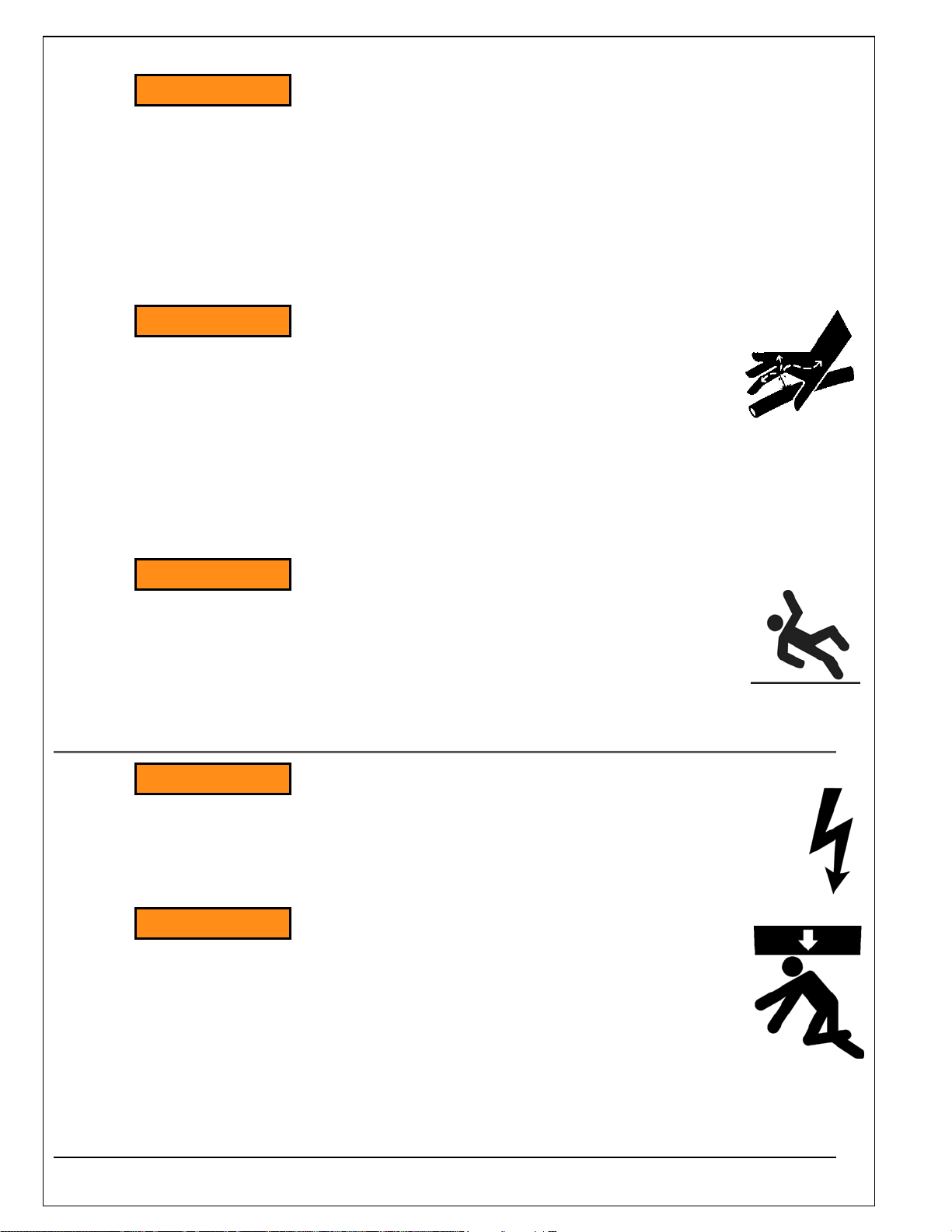
DANGER – Indicates a hazardous situation, which, if not avoided, will
result in death or serious injury.
WARNING – Indicates a hazardous situation, which, if not avoided, could
result in death or serious injury.
CAUTION – Indicates a hazardous situation, which, if not avoided, could
result in minor or moderate injury.
NOTICE – Indicates a situation that could result in damage to the lift or other
property.
3.2 Installation
Do not install lift in a pit unless pit has a bevel toe guard or other
approved toe protection. A shear point can exist which can cause
severe foot injury.
Lift platforms traveling below floor levels may create a toe hazard as load
passes top edge of pit. This may require guarding in accordance with
Federal Regulations. Guarding must be installed prior to operating lift.
^ DANGER
^ WARNING
^ CAUTION
NOTICE
^ WARNING

9
Prevent serious injury or death.
Depending on model, weight of lift ranges from 220 – 2600 lbs.
Use a properly rated lifting device to move and install lift.
3.3 Operation
Prevent serious injury or death.
Scissor lifts are designed for a specific load and application. Do not
change load or application from original design.
Overloading, or uneven loading, could result in load instability and cause
serious personal injury.
Stay clear of lift while lift is in motion.
Never stand, sit or ride on lift.
Prevent serious injury or death.
Lifts which travel to an elevation above floor level where distance between
floor and the underside of lift platform exceeds 60" must have the
scissors mechanism guarded per ANSI MH29.1.
3.4 Hydraulics
Fluids can be hazardous. Before servicing lift, check Material Safety Data Sheet (MSDS) to
understand the product, safe handling procedures, and first aid measures relating to product. Follow
this information when servicing or repairing lift.
Do not drain or pour any fluids or lubricants into ground. Check with local environmental agencies,
recycling centers, or your Autoquip dealer for correct disposal information.
Any time velocity fuses have been tripped, investigate cause of trip and
verify necessary corrective actions have been taken prior to operation of
lift.
^ WARNING
^ WARNING
^ WARNING
^ CAUTION
10
Prevent serious injury or death.
Do not attempt to remove Hydraulic Velocity Fuse (HVF) until maintenance
device securely supports lift and all hydraulic pressure has been relieved.
HVF is attached to elbow fitting in rod port of cylinder. Do not use a swivel
fitting between HVF and cylinder. If HVF is installed improperly, it will not
lock up in event of a hydraulic line failure.
Pressurized fluids can penetrate the skin.
Hydraulic hoses can fail from age, damage and exposure.
Do not search for hydraulic leaks without body and face protection. A tiny,
almost invisible leak can penetrate the skin, thereby requiring immediate
medical attention.
Use wood or cardboard to detect hydraulic leaks, never your hands.
Spilled fluids and lubricants may be slippery and may also
present a fire hazard.
Clean up spilled fluids and lubricants.
3.5 Maintenance
Prevent serious injury or death.
Disconnect and/or lock out electrical supply to power unit prior to any
maintenance being performed.
Prevent serious injury or death.
Never go under lift platform until load is removed and scissors
mechanism is securely blocked in raised position with
maintenance devices.
^ WARNING
^ WARNING
^ WARNING
^ WARNING
^ WARNING

11
3.6 Modifications
Prevent serious injury or death.
Do not modify lift. Autoquip cannot foresee and is not responsible for
injury or damage which results from unauthorized modifications or
misuse of lift.
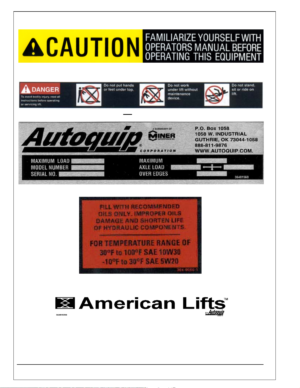
3.7 Labels
^ WARNING
12
A – 36401487
B – 36430050 If Not Equipped With Handrails
C – 36401560
D – 36400661
E – 36403230

13
F – 36401586
N/S – 36403343
To protect against death or serious injury, all labels must be on lift and
must be legible.
If any of these labels are missing or cannot be read, call Autoquip for
replacement labels.
^ WARNING
14
4. INSTALLATION
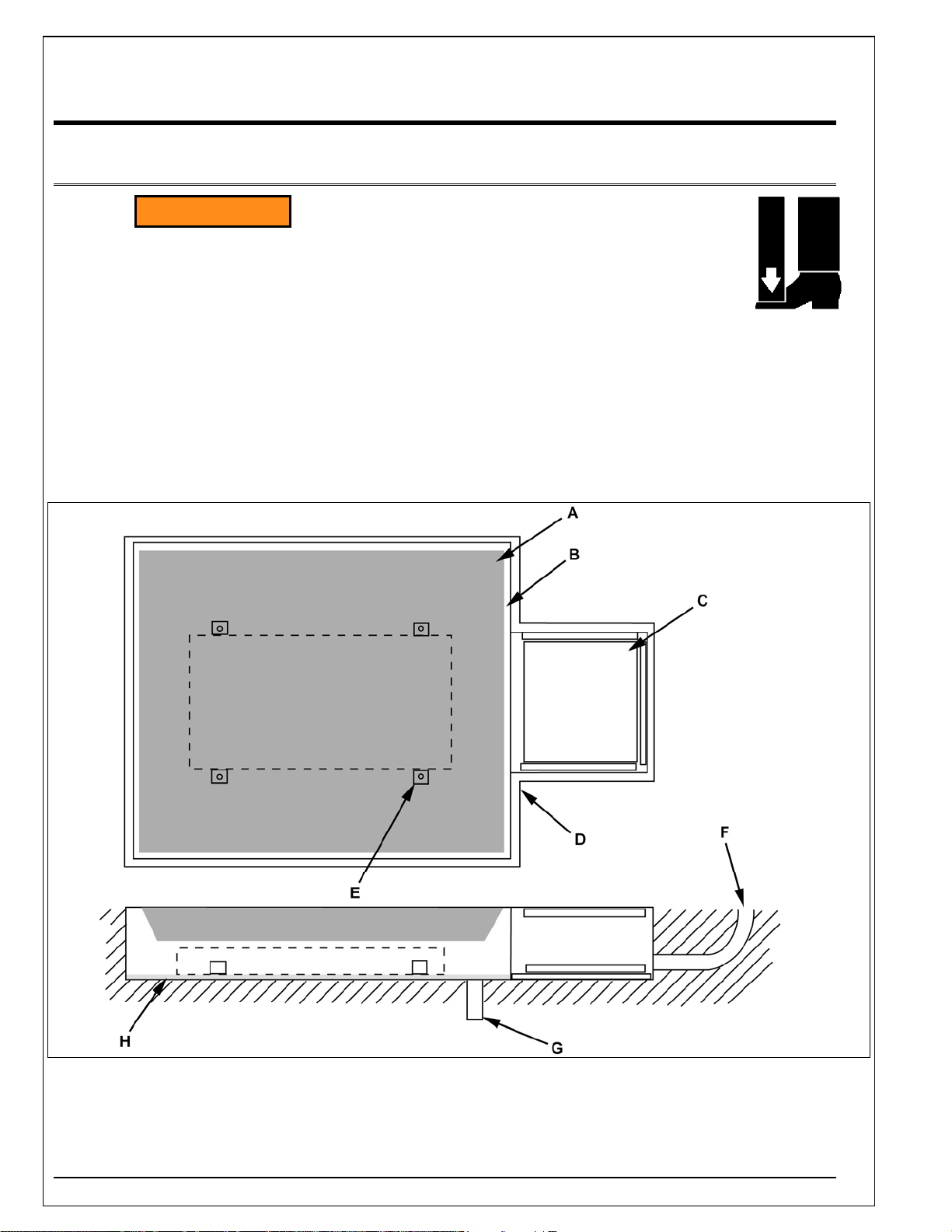
4.1 Pit Installation
Do not install lift in a pit unless pit has a bevel toe guard or
other approved toe protection. A shear point may exist which
can cause severe foot injury.
Lift platforms traveling below floor levels may create a toe hazard as load
passes top edge of pit. This may require guarding in accordance with
Federal Regulations. Guarding must be installed prior to operating lift.
1. Check pit dimensions. Pit must be 2" longer and 2” wider than lift platform to allow a 1” gap between
platform and pit. Pit depth should allow ½” for shims or grout.
2. Conduit (F) diameter must be a minimum of 2".
A – Lift Platform E – Lift Anchor Points (4)
B – 1” Gap Between Deck And Pit Wall F – 2” Min. Conduit, Cust. Inst.
C – Pit Access Hatch, Optional, Installed By Customer G – Suitable Pit Drain, Cust Inst.
D – Pit Curb Angle, Suggested Min. L2” x 2” x ¼”, Cust. Inst. H – ½” Grout Under Base
^ WARNING

15
3. Verify installation area is clean before starting. Check mounting surface of pit floor with a level or
straight edge. If floor is not level, add shims or grout under entire perimeter of base to achieve a
level and flat base installation. A level base is essential for proper wheel tracking and smooth lift
operation.
Prevent serious injury or death.
Depending on model, weight of lift ranges from 220 – 2600 lbs.
Use a properly rated lifting device to move and install lift.
4. Lower lift into pit and check for proper height. Lift must be solid and flush with pit angle framing (D).
If needed, shim to desired height. DO NOT “spot” shim. Shim along full length of frame. This will
prevent frame from sagging under load.
Prevent serious injury or death.
Electrical service installation must be performed by a licensed
electrician and conform to all local and national electrical codes.
NOTE: For larger horsepower motors, consult factory.
Motor Details Full Load Amps
HP HZ PH RPM
TIME
RATING @115VAC @208VAC @230VAC @460VAC
1/2 60 1 1725 30 MIN 8.4 - 4.2 -
3/4 60 1 1725 15 MIN 13.6 - 6.8 -
1 60 1 3450 5 MIN 12.8 - 6.4 -
1/2 50/60 3 1425/1725 30 MIN - - 1.8 0.9
3/4 50/60 3 1425/1725 15 MIN - - 2.6 1.3
1 50/60 3 2850/3450 30 MIN - - 3.0 1.6
1-1/2 50/60 3 1425/1725 30 MIN - - 4.6 2.3
5 ID 60 3 3450 2 MIN - 15.8 14.8 -
5 ID 60 3 3450 2 MIN - - - 7.4
5 HD 60 3 3475 30 MIN - 16.0 15.2 -
5 HD 60 3 3475 30 MIN - - - 7.6
Sound Level – Approximately 67.5 dB(A)
^ WARNING
^ WARNING

16
5. Temporarily connect electrical service and hydraulic hoses.
6. Fill hydraulic reservoir with proper type and volume of fluid.
7. Press “UP” operator control and raise lift one foot.
8. Press “DOWN” operator control and lower lift. Continue to hold down control for 60 seconds. Repeat
procedure five to seven times to bleed air out of hydraulic system.
9. Raise and lower lift as needed to make positioning adjustments.
10. Adjust platform to a clearance of 1” minimum around perimeter between platform and pit angle.
NEVER go under a raised lift platform until load is removed and
lift is securely blocked in raised position with maintenance
devices.
See "Maintenance Device" section of this manual.
Lock-out/tag-out power source.
11. Base frame of lift has pre-drilled holes for anchoring floor. Anchor lift to floor. Lifts with oversize
platforms have minimum pull out requirements of 2,000 lbs. for each anchor. See “Shimming And
Anchoring Lift To Concrete”.
^ WARNING

17
12. Route hydraulic hose or electrical cord through conduit in pit wall.
13. Make permanent electrical and hydraulic connections and operate lift through a few cycles.
14. Clean up debris and spilled oil from area. Dispose of oil in an environmentally safe manner.
15. Touch-up paint is available from Autoquip for repair of damaged paint surfaces.
16. Train personnel on lift operation, all safety features and procedures.
4.2 Shimming And Anchoring Lift To Concrete
Recommended concrete anchor bolts are: HILTI “Kwik-Bolt”, Molly Parabolt or similar.
1. Verify lift is positioned correctly.
2. Drill holes in concrete as specified by anchor bolt
manufacturer.
3. Install and tighten anchors as specified by anchor bolt
manufacturer.
4. After lift has been aligned, leveled and shimmed, and
anchors have been installed, pour grout under entire
base frame.
5. When grout has set and cured, tighten nuts on anchor
bolts.

18
4.3 Remote Power Unit Installation
1. The remote power unit is to be located in an area protected from the elements and should be
installed prior to the lift to facilitate lift operation during installation into the pit.
2. The remote contractor power unit is equipped with power unit mounting brackets and can be wall
or floor mounted using these brackets. If equipped with a vertical power unit, optional power unit
mounting brackets must be used for wall mounting.
3. The electrical work is to be done in accordance with local codes by a qualified electrician. See the
“Maintenance” section for the standard wiring diagram.
4. If permanent electrical work is not complete, some means of temporary power with an on/off device
for the motor will be required.
5. Fill the reservoir with oil per instructions in the "Maintenance” section.
4.4 Power Unit Wiring
4.4.1 Contractor Remote Power Unit
1. The Contractor Power Unit utilizes a 5 HP / 208-230-460 Volt / 60 hertz / 3 phase “Super-Torque”
intermittent duty motor with (one full lift cycle per 2 minute period) driving a high pressure positive
displacement pump assembly with an internal relief valve, check valve and down solenoid valve.
2. Because an Autoquip "Super-Torque" motor actually delivers substantially more horsepower than
the nameplate rating, it must always be wired for heavier current-draw than standard motors of the
same nameplate rating. However, because of the "Super-Torque" motor’s starting efficiency and
superior running characteristics, circuit components do not have to be as large as for standard
motors of equal delivered horsepower.
4.4.2 Vertical Remote Power Unit
1. The Vertical 'HD' Power unit utilizes a 5 HP/ 208-230-460 Volt / 60 hertz / 3 phase Heavy Duty
motor, (with a 30 minute continuous duty rating). The power unit is coupled with a high-pressure
positive displacement gear pump, and Autoquip Corporation’s patented Deltatrol valve assembly.
2. The motor connection diagram, should be referenced in connecting the motors to a power source.
Remember that heavy wire must be used all the way to the power source.

19
5. OPERATION
5.1 Raise And Lower Lift
Prevent serious injury or death.
Before operating lift, all personnel interacting with lift must read,
understand and follow instructions and safety warnings in this manual.
Adjusting safety relief valve may result in premature motor failure.
Do not adjust safety relief valve.
Raising loads exceeding rated capacity of lift may result in excessive wear and damage to lift.
Prevent serious injury or death.
Personnel must maintain a safe operating distance of at least 36” any time
lift is operated.
1. Verify all personnel are away from lift.
2. Press “UP” operator control to raise lift. Release control when lift reaches desired position.
Do not operate lift on relief for more than a few seconds. When on relief,
valve will make a squealing sound.
3. Press "DOWN" operator control to lower lift. Release control when lift reaches desired position.
^ WARNING
NOTICE
^ WARNING
NOTICE

20
6. MAINTENANCE
6.1 Maintenance Devices
NEVER go under a raised lift platform until load is removed and
lift is securely blocked in raised position with maintenance
devices.
Lock-out/tag-out power source.
This procedure describes the only factory-approved method of working under a lift. Follow these
instructions EVERY time you plan to reach or crawl beneath the lift to perform service or maintenance
– no matter how momentary that might be.
If the factory-provided maintenance devices are damaged or missing, stop immediately and consult the
factory for assistance. The manufacturer is not liable for your failure to use the approved maintenance
devices and procedures that have been provided.
1. All loads must be removed from the lift prior to engaging the maintenance devices. These devices
are designed to support an unloaded lift only. Failure to remove the load from the lift prior to
blocking could cause the failure of the maintenance devices and allow the lift to fall unexpectedly.
This can result in personal injury or death.
2. Raise the lift to its fully raised position. If you do not, the maintenance devices may not be able to
be placed properly in their designed blocking position.
3. The lift will is provided with two flip-in maintenance devices welded to the outside of the base
frame. The devices must be flipped over and resting inside the base frame (as shown at A) and
thus in the roller path of the lift (See Figure 6.1). Maintenance devices are disengaged at (B).
4. Lower the lift platform until the leg rollers make contact with both maintenance blocks. Re-check to
verify that both devices are fully and properly engaged with the leg rollers. If both left and right
maintenance blocks are not fully engaged the lift could fall unexpectedly.
Figure 6.1
^ WARNING
Other manuals for American Lifts P-25-005
1
This manual suits for next models
17
Table of contents
Other Autoquip Lifting System manuals


Popular Lifting System manuals by other brands


probst
probst TAS-UNI Translation of original operating instructions

Nexus 21
Nexus 21 AL-125 installation instructions

Titan
Titan HD4P-12000 Installation, operation & maintenance manual

Bestcare
Bestcare BESTLIFT PL400EF manual

Ekinex
Ekinex EK-BTV-BL instruction manual

Maxon
Maxon GPSLR Series Operation manual