Dato LJCC2040A User manual
user’s manual
1
TWO POST LIFT
LJCC2040A
U
Us
se
er
r’
’s
s
m
ma
an
nu
ua
al
l
Manufacturer:

user’s manual
2
MANUFACTURE AND SERVICE AGENT
TWO POST LIFT
Model:
Serial no.:
Manufacture date:
Manufacture:
Name:
Address:
Telephone:
Fax:
http:
E mail:
AUTHORIZED SERVICE CENTRE
/ / /

user’s manual
3
INSTRUCTION
Though we have considered about the machine safety during design and manufacture, proper training and
frequent operation can be better for the safety. Forbid to operate or repair the lift without reading this user’s
manual.
Check the nameplate on motor and currency request on nameplate, only professional electrician is allowed to
connect the power.
Forbid to load vehicle over 4000KG!
Read the warning content in user’s manual carefully!
We do not take responsibility to the damage due to improper use or operation.
Manufacturer owns the right to make little changes for the manual owing to the
improvement of technology.
CATALOGUE
Catalogue
1 Packing …………………………………………………………………
2 Description of machine …………………………………………………
3 Installation ………………………………………………………………
4 Adjustment ………………………………………………………………
5 Maintenance and care ……………………………………………………
6 Trouble shooting …………………………………………………………
7 Appendix …………………………………………………………………

user’s manual
4
Chapter 1 Packing
Discharge the outside packing and other packing material, to check whether any damage or
missing during transportation according to “packing list”. If find damage or missing, should
notice the carrier immediately.
PAC ING
Standard scheme: main post and its components, sub post and its components(1#), hydraulic
unit(2#),standard equipments totally 2 cases.
Chapter 2 Description of machine
2.1 USAGE
This two post lift can lift various vehicles which weight is less than 4000kg. And it is
suitable for vehicle test, repair, maintenance and care.
This lift is designed to lift vehicles, not for other usage.
Forbid to use for washing and spraying vehicles!
Forbid to lift vehicle which weight is over 4000KG!
2.2 FEATURES
Design and manufacture according to relevant standard, and machine performs stable and reliable.
With hydraulic locking and mechanical locking system, safety and reliable.
With insurance bar for top protection, to prevent effectively the vehicle from being damaged.
With safety valve and antiknock valve in case of hydraulic failure or over loading, to prevent the lift from
lowering quickly when oil pipe bursts.
Double cylinder drive, to lift and lower stably.
Adopt imported hydraulic and electrical components from Italy, Germany and Japan.
2.3 MAIN FABRIC PRINCIPLE:
Lifting fabric: Each post has one cylinder, when pump the oil into the cylinder, the cylinder pole will move
upwards, to hold the carriage move upwards.
Support fabric: After driving the vehicle into the working area, adjust the angle of arms and length of extension
arms, to ensure the arms support on the effective vehicle bearing point.
Fix the position of vehicle by arm orientation fabric, in case of slipping.
Then adjust the screw to fit different height chassis.
Balance fabric: To keep the balance during lifting, connect the two carriages with two steel cables to ensure the
synchronization of the two. Then tighten the steel cable, or it will not synchronize.
If carriages, arms are not in level, adjust the steel cable nut, to ensure the carriages and arms in level. Then
tighten the cables to ensure the synchronization.
Electromagnetic safety locking fabric: During lifting, each post has safety locking device to ensure the lift can
stop reliable without falling.
Principal of electromagnetic safety locking: The upper side of safety racks adhibit on the safety teeth for the
angle and deadweight. The carriages push the safety rack and go up step by step. If failure of lift and begins to
lower quickly, safety rack will clip on the teeth to stop the carriage to stop lowering. (See picture 9 and 10)
There are orientation device on the arms, to lock arms when they are in proper position, which can prevent the
vehicle from slipping.
user’s manual
5
Chapter 2 Description of machine
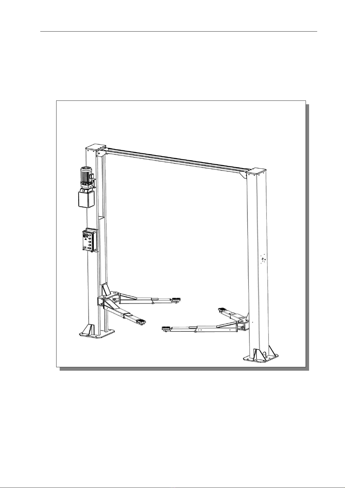
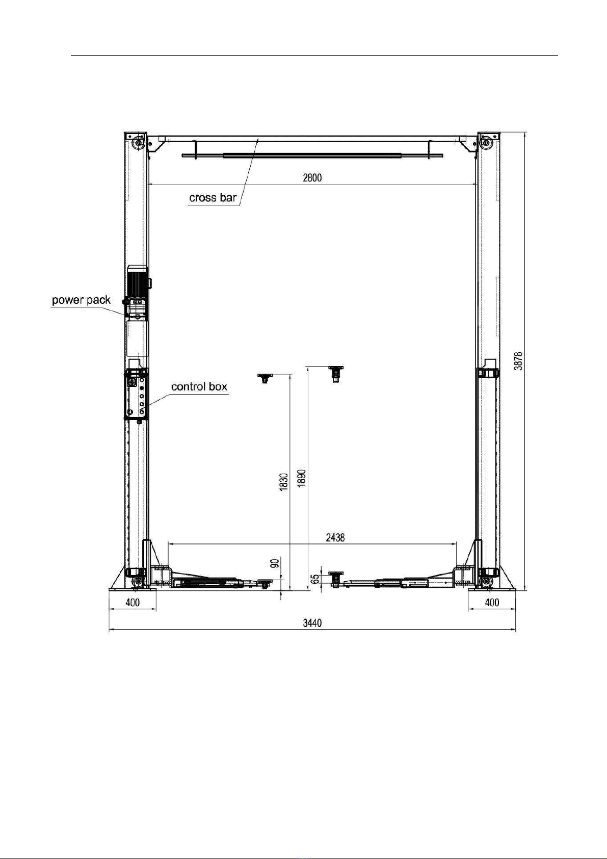
2.4 CONFIGURATION DRAWING:
Picture 1 (dimension drawing)

user’s manual
6
Chapter 2 Description of machine
Picture 2 (arm extension drawing)

user’s manual
7
Chapter 2 Description of machine
2.5 TECHNICAL PARAMETER
Table 1
Item
Parameter
Drive Electrical hydraulic
Max lifting weight 4000kg
Lifting height 1830/1890mm
Original height 98/160mm
Lifting time ≤50S
Lowering time ≤60S
Pass width 2390mm
Overall width 3440mm
Overall weight 870 kg
Voltage AC 400V or 230V ± 5% 50Hz
Machine power 2.2 KW
Hydraulic oil 13L 20# high abrasive hydraulic oil (prepared by user)
Working temperature
5 40℃
Working humidity 30 95%
Noisy level < 76db
Installation height Height above sea level ≤1000M
Storage temperature
25℃~55℃
Installation place Indoor
user’s manual
8
Chapter 3 Installation
3.1 INSTALLATION NOTIC
Improper installation will cause damage to machine or personnel. We do not take responsibility to any direct or
indirect damage due to improper installation or operation.
The proper installation floor should be level, to ensure level lifting and lowering. Any slant can affect the
performance of the machine.
Forbid to install the machine on asphaltum floor. According to the floor requirement, can only install machine
on good condition concrete floor, no crack and other defects.
Without certify permit from architect, forbid to install machine on the floor which has empty room downstairs.
Avoid installing machine near warming device, water faucet, air humidifier and ingle.
Power supply: Before installation, get ready for the power supply.
3.2 INSTALLATION PROCESS
3.2.1 GENERAL ORIENTATION
Lift can only be installed on concrete with steel to reinforce.
Thickness of concrete ≥ 200mm,to ensure the intensity reach to 3000PSI(2.1Kg/mm
2
)upwards。
Height of indoor should be over 4000 mm,regard to hold enough space for all lifting vehicles(approximate 4m
from the lift center)
Distance from post to wall should be at lease 1200mm. In case of emergency situation or working convenience,
should consider about enough space for safety channel.
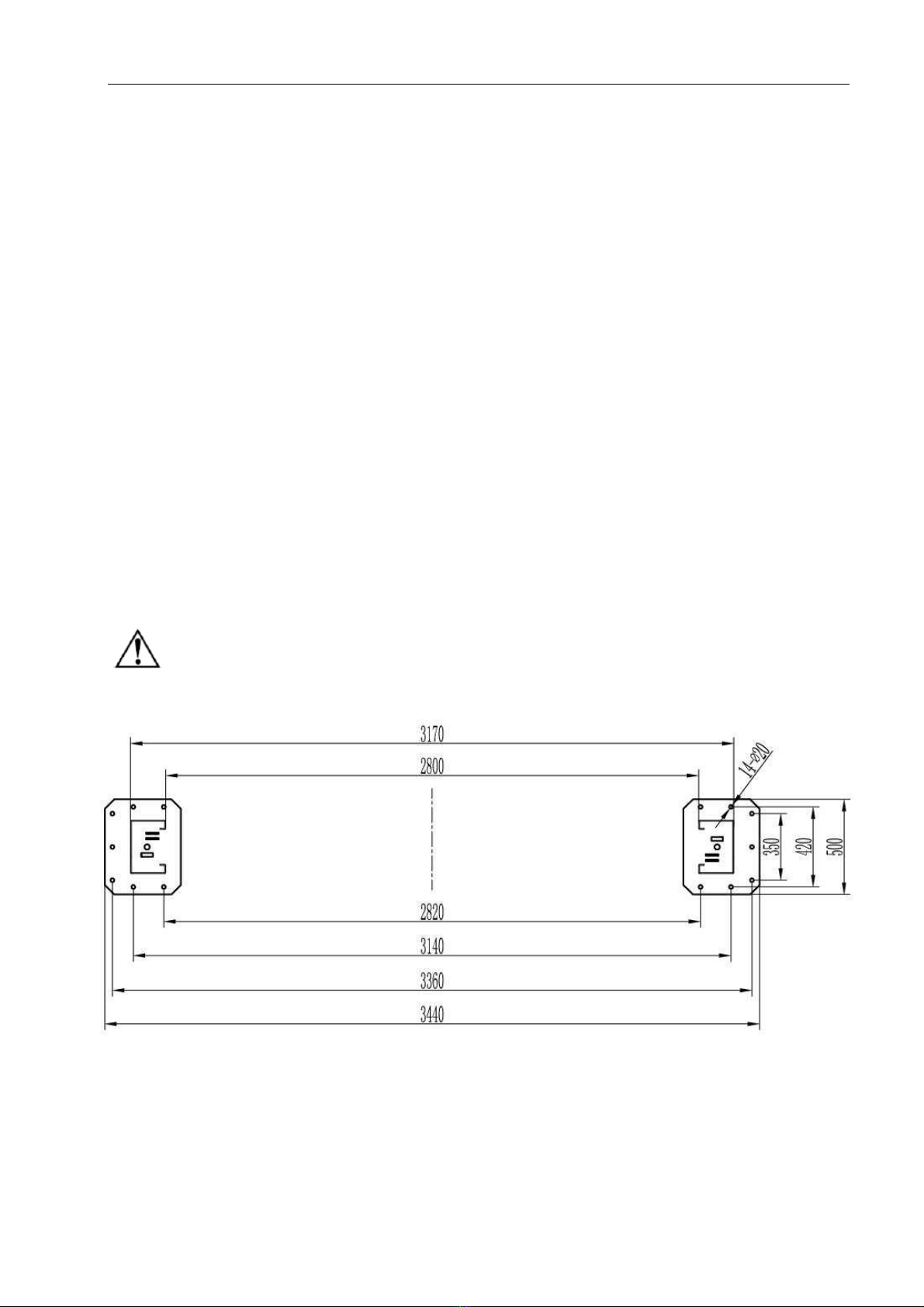
3.2.2 FLOOR LAYOUT
It’s very important for the floor layout (picture 3). If it’s not correct, there may be some
problems during installation and operation. The total level error is less than 4mm, which
can decrease the problems during final installation.
Picture 3 (floor layout)
user’s manual
9
Chapter 3 Installation
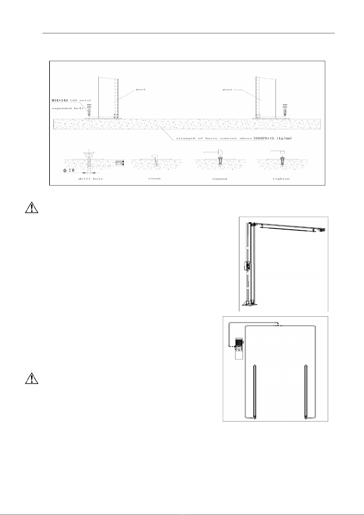
3.2.3 INSTALLATION DRAWING OF POST
Notice: Drill hole withφ19mm aiguille and then anchor with pneumatic tools. The depth of hole and bolts
should be the same and insert the bolt.
The air anchor, made against the washer to under the post. When
fastening to the use of torque wrench, do not use impact tools to tighten.
3.2.4 STEEL CALBE INSTALLATION
1 Fix the posts according to the drawing, and place the main
post, slave post according to picture 4. Drill hole for expansion
bolt withφ19mm aiguille and no need to fix the bolt at the
moment.
2 Check and ensure the posts dimension is in accordance with
picture 5. Test the vertical of post with spirit level (construction
using type).
3.2.5 ORIENTATION OF CROSSBEAM
1 Fix the crossbeam according to the drawing. That side
with limit switch should be installed on the post with
hydraulic unit, then fasten with screw.
2 Fasten the expansion bolt.
Notice: Select suitable steel shim as gasket and insert under the
post bottom, to make the post vertical. The thickness of steel shim
should less than 5 mm.
3.2.6
Oil pipe and accessory installation
1 Connect the oil pipe and cable through the oil pipe slot.
2 Fix the hydraulic station, then connect the oil
pipe fittings and wire plug.
Picture 4 (post installation)
Picture 5 (post orientation)
Picture 6(oil pipe list and installation)

user’s manual
10
Chapter 3 Installation
3.2.7 STEEL CABLE INSTALLATION
1 Open the cover of carriage and fix the carriage on the first tooth. Connect the steel cable and
tighten the nut.
2 Set the carriage on the lowest locking point, and then adjust the steel cables.
3 Ensure no cross and mistake installation of cables, also ensure the steel cables are on top the
pulley.
3.2.8 INSTALLATION OF OTHER PARTS
Unlocking device installation:
1 Install safety part and steel cable according to unlocking device 1 and 2, and tighten the cable
with cable clip. (See picture 8 and picture 9)
Important notice:
Correct standard of unlocking adjustment is as follow: When nut of electromagnetic steel core is at
the end (see picture 9), two safety boards strike close to the carriage, to lock the carriage effective.
When the nut of electromagnetic steel core is at the root of thread, two safety boards can open
together and carriage lowers. The synchronization of two carriages depends on the force of steel
cables.
Install and fix four swing arms on carriage with hinge axis, and fix the support block.
Picture 7 oil pipe connection cable
Picture 9 (unlocking 2)
Picture 8(locking 1)

user’s manual
11
Chapter 3 Installation
INSTALLATION OF ARMS:
-Fix the long and short sway arms with hinge axis on the carriage according to the floor layout.
Install the correspond long and short extension arms and fix with M8×12 bolt to avoid slipping.
Put the adapter to the holes on extension arms (can choose differ height adapter to suit different
height chassis)(see picture 8:)
3.2.9 INSTALLATION OF CONTROL BOX OF WIRES
Fix the control box on the post with bolt.
Connect the wires according to electrical diagram and air loop according to air loop diagram.
Only authorized qualified personnel can install the electrical part.
Open the control box cover first.
Power connection:
Connect the 3 phase five wires (3×2.5mm
2
+2×1.5 mm
2
) for the power supply to the terminal of
control box according to the circuit diagram.
If for 230V connection, connect to the control box according to the circuit diagram.
-Connection for the electromagnetic steel of release:
For detail connection, please see the circuit diagram.
Up limit switch connection:
For detail connection, please see the circuit diagram.
Picture 10 (up limit switch connection)
Bolt limit
Picture 8

user’s manual
12
Chapter 4 Adjustment
4.1 PREPARATION BEFORE ADJUSTMENT
Upright adjustment:
Use plumb to fix the top of post and check whether its install position is upright.
Then hammer the expanded bolt and tighten the ground bolt cap.
Only can hammer the expanded bolt after the expired period of the concrete and the gap
between base plate and ground surface must be filled with iron plate or concrete and then
tighten the anchor bolts.!
4.2 PROCESS OF ADJUSTMENT
Check whether the connection of power is correct, pay attention to the turning of 3 phase motor.
-Ensure all bolts are tightened enough.
Press “UP” button, safety board goes up with carriage and releases the lock. Release the button,
carriages stop lifting.
Press “DOWN” button, to pull in electromagnetic steel, and the carriages lower. Release the
button, carriages stop lowering.
4.3 SYCHRONIZATION ADJUSTMENT
Repeat to lift and lower the lift several times, to ensure the tensile force of two steel cables. If not,
adjust the cable nut.
Press “UP” button, to check whether the lifting and lowering of carriage is synchronized. If not,
adjust the cable nut.
4.4 LOADING TEST
To check whether hydraulic system works normally when loading heavy weight.
Notice:
Check every oil pipe and fitting, to ensure no leakage before operating the lift.
Use all the arms when lifting vehicle on the recommended point of the chassis.
Vehicles barycenter must be
in the middle of two support arm.
Remove or install any heavy part, one should use safety support like jack to keep the balance of vehicle.
When lifting or lowering with loading, forbid personnel to stand under the arms or vehicle and keep in case of
danger.
Cut off all the power when lift is not on work.
Chapter 5 Maintenance and care
Notice
ATTENTION:
All bearings and hinges on this machine must be lubricated once a month
The lock latch, steel cable, and some other moving parts should be lubricated monthly.
The hydraulic oil must be replaced once a year. The oil level should always be kept at upper limit
position.
Check the steel cable every three months and if there is some abrasion, something wrong, stops
using and contact with the manufacturer.
Check the integration of the insurance system
every day.
When change hydraulic oil, put machines to the lowest position, have the oil tank empty,
when add new oil, should be filled by filter.

user’s manual
13
Chapter 6 Trouble Shooting
Failure phenomenon
Cause and Phenomena
Resolutions method
connection of power supply
wires or zero wire is not
correct
Check and correct wires connection
the AC contactor in the
circuit of the motor does not
pick up
If the motor works when forcing the
contactor down with an isolation rod, check
the control circuit. If the voltage at two
ends of the contactor coil is normal, replace
the contactor.
The motor doesn’t
run in lifting
operation
UP button failure
Check the contact point of the button and
wires connection and exclude.
The motor turns reverse
Exchange the phases of the power supply
wires
lifting with light load is
normal but no lifting with
heavy load
The set safe pressure of the over flow valve
may be increased by turning the set knob
right ward slightly. The spool of the
lowering solenoid valve is stuck by dirt.
Clean the spool.
the amount of hydraulic oil
is not enough
Add hydraulic oil
When lifting
operation, the motor
runs but it is no
lifting movement
the descend valve is not
closed fastened
Check the descend valve and exclude.
①
the safety pawl are not
released from the safety
teeth
First lift a little and then lowering When press lower
button, the lift is not
lowering
he solenoid air valve does
not work
Check the solenoid loop circuit and solution
Two carriages are not
synchronized when lift
The force of two steel cable
different or force not enough. Adjust the cable adjustment nut.
Leak oil
Oil pipe fitting loosen
Screw down the pipe fitting
user’s manual
14
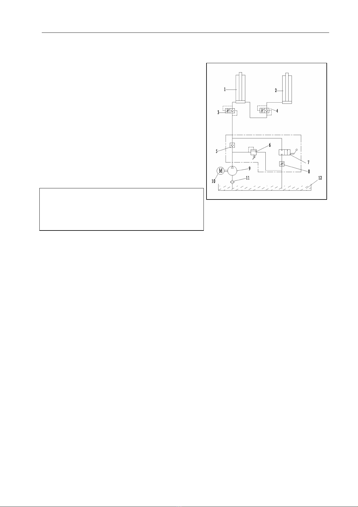
1/2cylinder 3/4 antiknock valve 5 check valve
6 overflow valve 7
manual rotate valve
8 throttle valve
9 pump 10 motor 11 filter 12 oil tank
Chapter 7 Appendix
7.1 HYDRALIC SYSTEM
When pressed “UP” button to start the motor, to
pump oil from oil tank to cylinder, and to push the
cylinder piston to move. Overflow valve is closed and
the pressure is been set before packing in factory, to
ensure the maximum loading of lift. When the system
pressure is over max pressure, overflow valve will
work to have the oil back to oil tank.
Release “UP” button, motor stops to wok and
carriages stop lifting.
Press “DOWN” button, to connect the
electromagnetic steel and open the safety rack, pump
begins to have oil back to oil tank and the carriage
begins to lower.
Picture 11 (hydraulic schematic drawing)
user’s manual
15
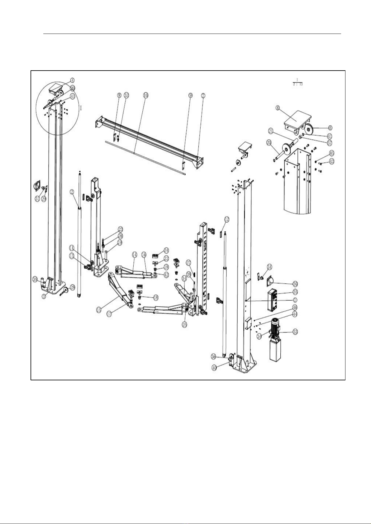
7.2 EXPLODED DRAWING OF MAICHINE
user’s manual
16
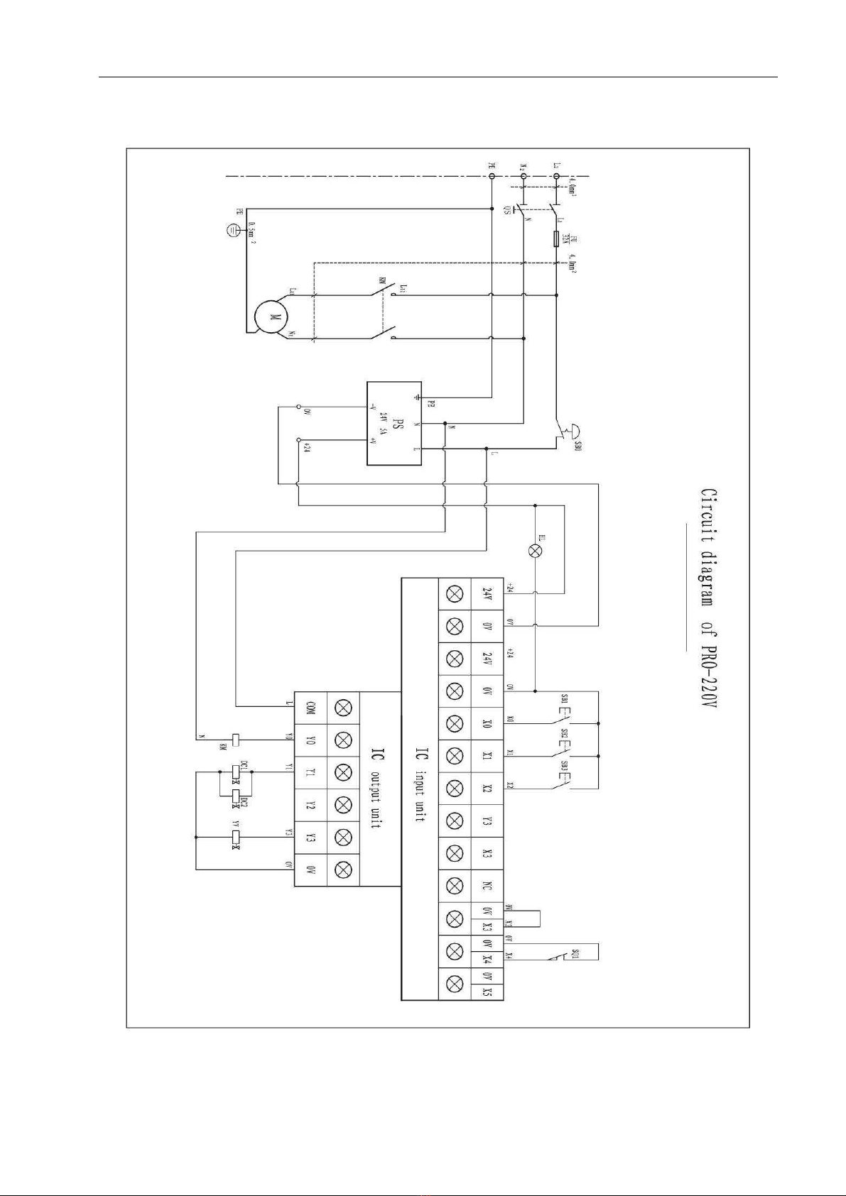
Circuit diagram(220V):
user’s manual
17
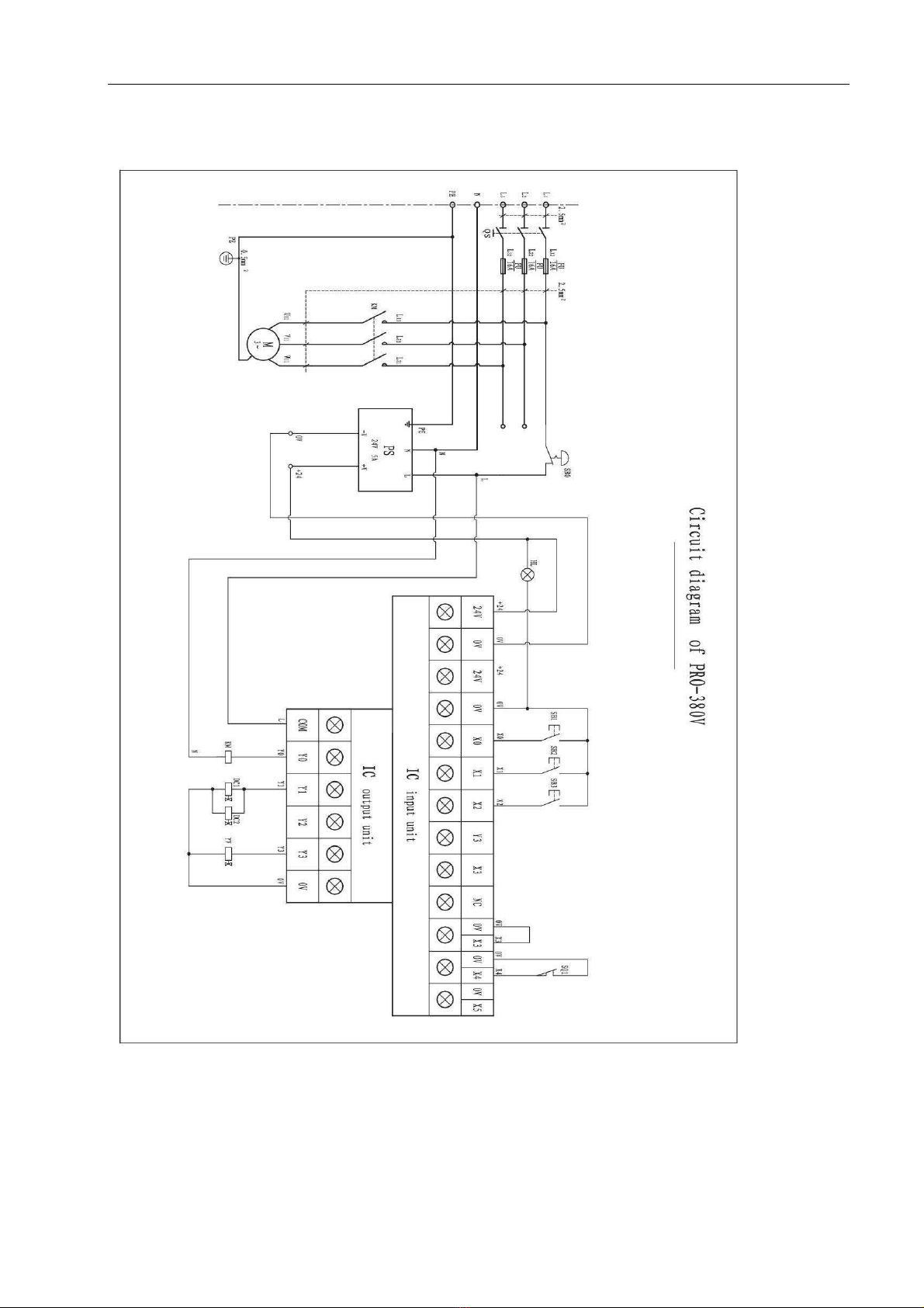
Circuit diagram(380V):
Table of contents
Other Dato Lifting System manuals


Popular Lifting System manuals by other brands


morse
morse 8A-GT-125 Operator's manual

PFlow Industries
PFlow Industries B Series Owner's, Installation and Maintenance Manual

AUTOPSTENHOJ
AUTOPSTENHOJ Masterlift 2.30 installation instructions

Leggett & Platt
Leggett & Platt Adjustable Base Setup guide

LGMG
LGMG SR1018D Operation manual

Grundfos
Grundfos Multifit MD Series Installation and operating instructions


