Toa RX-31C Instruction Manual

Operating Instruction Manual
TOA ELECTRIC CO., LTD.
KOBE, JAPAN
Model RX-31C
TOA MIXING CONSOLE

General Description......................................2
Features......................................................2
Front Panel..................................................3
Rear Panel...................................................4
Rac Mounting Instructions............................5
Input Connections.........................................6
Connection Examples.....................................7
Bloc & Level Diagrams.................................8
Avoiding Ground Loops..................................9
Effective Mixing..........................................10
Specifications..............................................11
Characteristic Diagrams.................................12
Appearance..................................................12
1. XLR (Cannon) Connector
XLR Connectors are wired to NAB standards. Pin 1 is ground (shield), Pin 2
is cold (low, minus), Pin 3 is hot (high, plus).
2. Descriptions of co ponents and functions
Various mixing console descriptions are used, depending on individual
manufacturer's standards. In our Operating and Instruction Manual, explana-
tion of components and functions is made according to our usage for them.
3. Phanto Power Supply
The RX-31C incorporates a 48V DC Phantom Power circuit. If phantom power
is required, the Phantom ON/OFF switch on each input channel for which
phantom power is required should be "on". When using phantom power, avoid
connecting unbalanced microphones or connecting other circuits in which the
center tap of the unit's input transformer is grounded.
–1 –
Contents
Precautions

The RX-31C is an eight input, one program output and one line output mixer,
designed especially for sound reinforcement systems in auditoriums, churches
and similar applications. Each input channel is transformer isolated and accepts
either a low impedance microphone or a high level source. A MIC/LINE selector
switch on each input channel permits selection of the type of source. A phantom
ON/OFF switch on each input channel applies 48V DC phantom power for con-
denser microphones. An input TRIM control on each input channel provides 30dB
of gain adjustment prior to the main channel fader. A channel ON/OFF slide
switch on each input channel connects or disconnects the input signal to the mix-
ing bus. The adjacent green LED illuminates when the channel is "on". An LED
bar graph pea meter with 12 sections calibrated in 3dB steps responds instant-
ly to the program output level. Also featured is a 5 band (pea ing) equalizer with
rotary controls plus switchable high pass/low pass filters for reducing wind and
scratch noise. A headphone output enables the operator to audition each input
channel, AUX input, program output or line output, depending on the position of
the phones selector switch. With an optional brac et, the RX-31C is usable in a
rac -mounted configuration.
1. Phantom power switches, each channel
2. MIC/LINE selector switches, each channel
3. Individual input level Trim controls, each channel
4. Channel ON/OFF switches
5. Pea indicator, each channel
6. LED pea meter with 12 sections calibrated in 3dB steps
7. High pass and Low pass filters
8. Five band (pea ing type) equalizer (rotary type)
9. Headphone jac
10. AUX IN and REC (recording) OUT jac s
11. Rac -mountable with an optional brac et, occupies 7 spaces
–2 –
General Description
Features

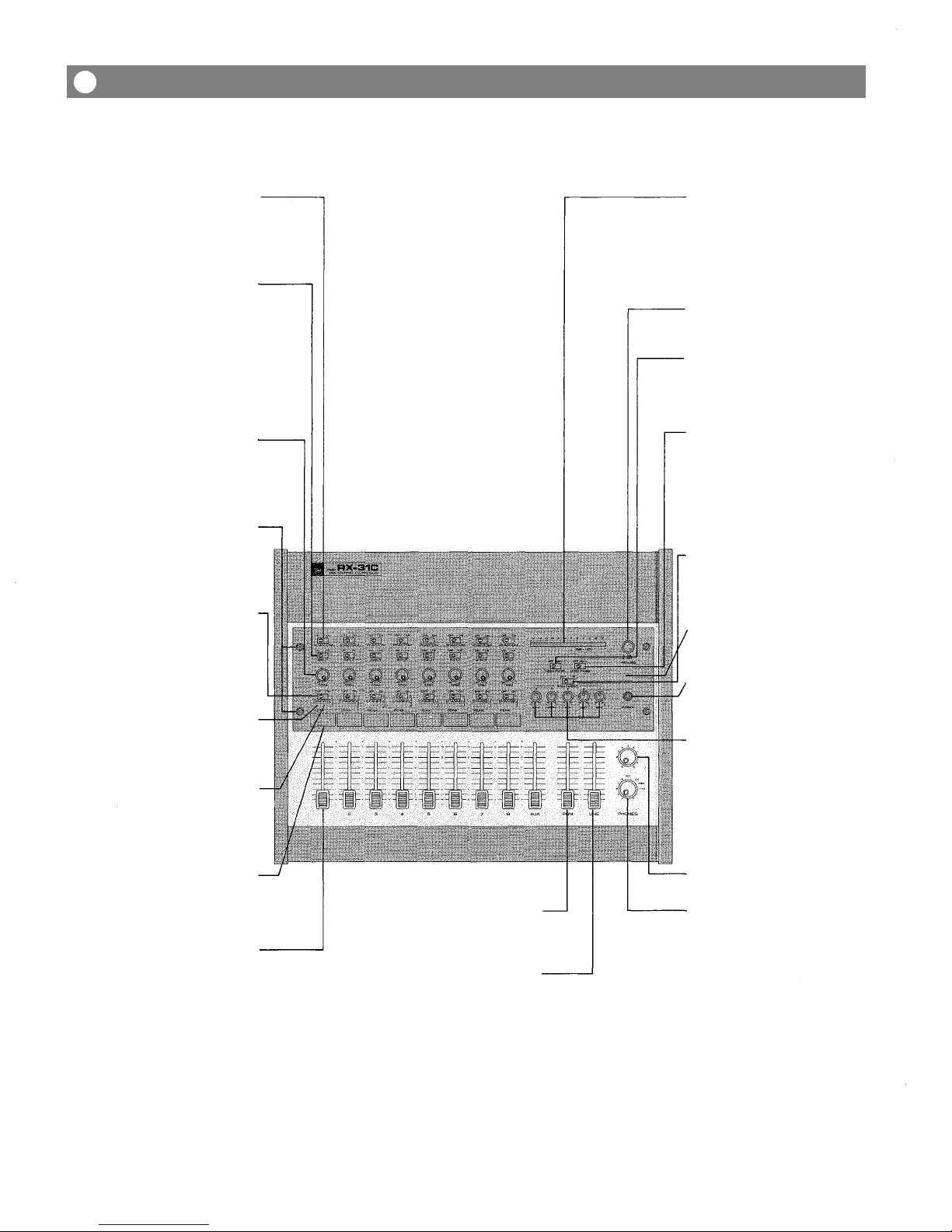
Phanto Power (48V DC) Switches-
The individual channels' switches should
be "on" when one or more condenser
microphones are connected, and the
switch should be "off" when dynamic
microphones are used.
MIC/LINE Input Selector Switch (INPUT)
Selection is made in accordance with the
incoming signal. When dynamic micro-
phones are connected, the selector switch
must be set to the MIC position. When a
high level source is attached, it must be
set to the LINE position. The LINE position
is designed to automatically disconnect
the phantom powering circuit even if the
phantom power switch is "on".
Input Tri Control (TRIM)
Controls the gain of the head-amplifier
stage of each input channel, providing an
additional 30dB trim from the sensi-
tivity chosen at the input level selector
(MIC/LINE switch).
Security Cover Stud Screw
The stud screws are provided to mount
the smo ed plastic security cover, which
prevents inadvertent control changes
after all controls (except the input and
master faders) are properly set.
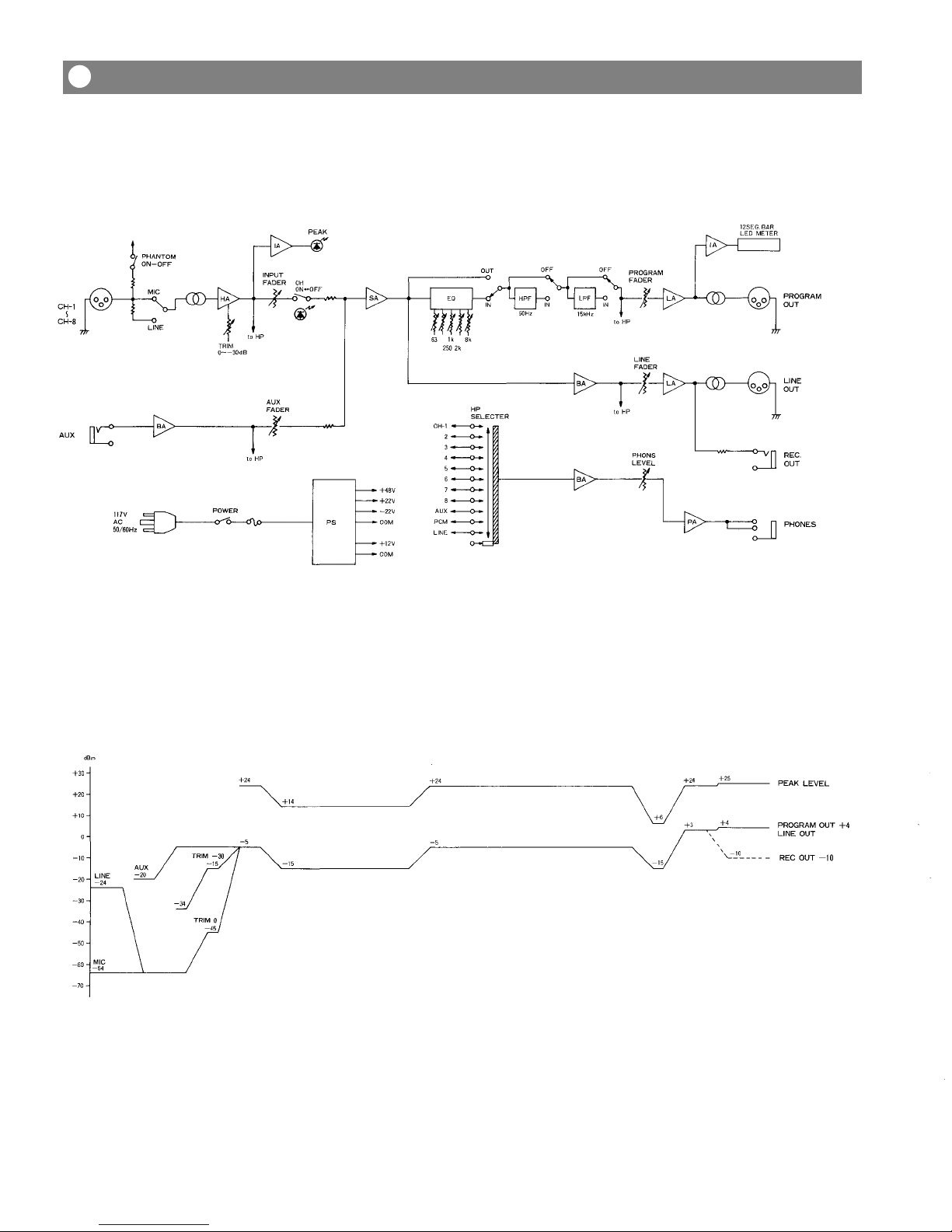
LED Peak Meter
The LED pea meter with 12 sections
calibrated in 3dB steps, responds instan-
taneously to the program output level.
Green LED's indicate the level below the
+4dBm nominal level, and red LED's
indicate the level above the +4dBm
nominal level.
Power Switch
Pushbutton alternately switches AC
power "on" and "off".
High Pass Filter
The switchable high pass filter provides
flat response when OFF, but can be set to
cut the mixer's frequency response below
50Hz at a 6dB/octave rate.
Low Pass Filter
The switchable low pass filter provides
flat response when OFF, but can be set to
cut the mixer's frequency response above
15 Hz at a 6dB/octave rate.
Equalizer IN/OUT Switch
The equalizer IN/OUT switch puts the
mixed signal either in or out of the
equalizer. The OUT position provides flat
response.
LED AC Power Indicator
The green LED illuminates when the
power switch is "on".
Headphone Jack
Headphones (mono or stereo) with mini-
mum 8-ohm load impedance may be
plugged into this jac for mono audition.
Input Channel ON/OFF Switch-
(CHANNEL)
The slide switches provide quic connects
or disconnects of individual channel input
signals to the mixing bus.
LED
Indicator-
The green LED illuminates when the input
channel switch is "on".
LED Peak Indicator (PEAK)-
The pea indicator illuminates if clipping
occures in the head-amplifier stage of the
corresponding input channel. When the
light comes on, adjustment should be
made with the input TRIM control.
Equalizer
The equalizer consists of 5 bands of
pea ing equalization (rotary type), and
provides l0dB of boost and l0dB of
attenuation at 63Hz, 250Hz, I Hz, 2 Hz
and 8 Hz, based on ISO standards.
Phones Volu e Control
Controls headphone volume.
Writing Block-
The identification of the input equipment
or microphone location can be written on
the bloc with an erasable felt pen or a
wax pencil.
Input Fader-
The fader continuously varies the channel
level to the mixing bus. Nominal level is
the "0" position. The fader is calibrated
in dB and assures very smooth operation.
Master Progra Fader
Controls the overall signal level of the pro-
gram mix fed to the program output.
Line Output Fader
Controls the overall signal level of the mix
fed to the line output.
Phones Selector
The phones selector is a 12-position
(including "off") rotary switch used to
choose the signal which is fed to the head-
phone jac . A signal is selected from
among the program output, line output,
AUX input, and each input channel (1 to 8
input channels).
–3 –
Front Panel

Progra Output Connector (PGM OUT).
The Program Output Connector is bal-
anced and transformer isolated. The
nominal signal level and impedance are
+4dB and 600 ohms, respectively.
Line Output Connector (LINE OUT)
The Line Output Connector is balanced
and transformer isolated. The nominal
signal level and impedance are +4dB and
600 ohms, respectively. The output signal
is derived prior to the equalizer section.
Input Channel Connector(s) (INPUT)
The XLR connectors are balanced,
transformer isolated, and accept either
low or high impedance sources, depend-
ing on the position of the MIC/LINE
selector switch on the front panel, the
nominal signal level and impedance in the
MIC position are -64dBm and 1.5 ohms,
respectively. In the LINE position, the
nominal signal level and impedance are
-24dBm and l1 ohms, respectively.
AC Power Cord
Cord Hanger
-AUX Input Jack (AUX IN)
This jac is unbalanced and accepts low
or high impedance sources at nominal
-20dB level. The AUX input will accept
feeds from a tape player, wireless tuner
or other high level devices.
AC Fuse (1A)
The fuse should be replaced only with
one of identical value and type.
Recording Output Jack (REC OUT)
This is a high level, high impedance
(nominal 10 ohms) unbalanced output
jac (nominal level -l0dB). This signal is
pre equalizer and suitable for feeding a
tape recorder or other high level devices,
devices.
–4 –
Rear Panel

The RX-31C is designed to be used either console style or to be rac -mounted,
using a pair of optional brac ets (model MB-701). The following procedure should
be followed to rac -mount the mixer using the MB-701.
1. Remove both side panels and armrest. (Remove 6 screws securing each side
panel).
Side Panel
Side Panel
Ar rest
2. Mount the MB-701 brac ets on both sides of the chassis. (Use the screws
removed from the side panel to secure the brac ets).
MB-701 Bracket
MB-701 Bracket
3. The rear panel and blan panel should now be changed in position to easily
accept equipment connections on the RX-31C in the rac .
4. Reverse the positions of the rear panel and blan panel, as shown below.
Front Panel
Front Panel
Rear Panel
Corner Fra e
Blank Panel
Corner Fra e
Power Chassis
Blank Panel
Power Chassis-
Rear Panel
a. Remove the rear panel, corner frame and blan panel,
b. Put the rear panel in the original position of the blan panel,
c. Put the corner frame bac in place.
d. Put the blan panel in the original position of the rear panel and ta e off the
rubber feet.
–5 –
Rack Mounting Instructions

Generally spea ing, there are two rules to follow when connecting equipment
outputs to the inputs of other equipment.
1. Properly match the impedances of the outputs and inputs.
2. Connect low impedance outputs to high impedance inputs.
It goes without saying that not only input and output impedance matching but also
level matching should be ta en into consideration. Each input channel of the
RX-31C is provided with an input TRIM control, so the usable signal level range is
very wide. Input impedances and levels are shown in the following table.
CONNEC-
TION
INPUT
(1-8)
AUX
INPUT
SELECTOR
MIC
LINE
ACTUAL LOAD
IMPEDANCE
FOR USE WITH
NOMINAL
50 TO 250
MICROPHONES
OR LINES
OR LOWER
IMP. LINES
OR LOWER
IMP. LINES
TRIM
POSITION
0
-30
0
-30
SENSITIVITY
(AT MAX GAIN)
—84dBm (0.049mV)
—54dBm (1.55mV)
—44dBm (4.9mV)
—14dBm (155mV)
—40dBm (7.75mV)
INPUT LEVEL
NOMINAL
—64dBm (0.49mV)
—34dBm (15.5mV)
—24dBm (49mV)
+ 6dBm (1.55V)
—20dBm (77.5mV)
*MAX. BEFORE
CLIP
—35dBm(13.8mV)
—5dBm(436mV)
+ 5dBm (1.38V)
+ 35dBm (43.6V)
+ 9dBm (2.18V)
CONNECTOR
XLR TYPE
XLR-3-31
PHONE JACK
Sensitivity is the level required to produce a program out level of +4dBm.
0dBm is referenced to 0.775V RMS.
All XLR type connectors are floating (balanced) and transformer isolated. Phone
jac is unbalanced.
If the line going from one piece of equipment to another is long (more than 5m), we
recommend that balanced outputs be connected to balanced inputs.
As is described in the beginning of the Operating Instructions Manual, the
connectors of the RX-31C are wired in accordance with NAB standards: Pin 1 is
ground (shield), Pin 2 is cold (low, minus), Pin 3 is hot (high, plus).
INPUT SPECIFICATIONS
–6 –
Input Connections

DISK PLAYER
WITH A MM CARTRIDGE
RIAA EQUALIZER
WIRELESS TUNER
SUCH AS WT-02,
WT-06
Input channels 1-8 should be
connected with low impedance
(50-ohm~600-ohm) microphones
when the MIC/LINE selector switch
is set to the MIC position. At LINE
position the impedance of the in-
puts changes to 1l ohms, so that
associated equipment with an out-
put impedance of less than 1l
ohms should be connected to the
inputs. The inputs are balanced,
transformer isolated no matter
what the position of the MIC/LINE
selector switch.
CASSETTE TAPE DECK
for recording
TAPE-DECK
PLAYBACK DECK
STAGE MONITOR WITH
A BUILT-IN POWER
AMPLIFIER
POWER AMPLIFIER
A-906
–7 –
Connection Exa ples

RX-31C BLOCK DIAGRAM
LEVEL DIAGRAM
–8 –
Block and Level Diagra s

AC ground is provided to the RX-31C and all associated equipment, and this can
sometimes causes an increase in hum noise. This is because a ground loop is made
through the shields of the connection cable and the AC line as shown Fig. 1.
Fig.
1
To solve this problem, either the chassis ground of the signal line should be
disconnected at either piece of equipment, or disconnect the chassis earth
ground, so that the ground loop is eliminated. However, it is highly dangerous to
disconnect the AC ground, as microphones and other equipment connected to the
mixing console are often touched directly by hand. This may cause an electric
shoc , in the case of electricity lea age, if any other connected equipment is
touched. Therefore the chassis ground line should be disconnected. Whether or
not to disconnect the chassis ground line of other equipment depends on various
conditions. Therefore, this should be chec ed and determined for each installa-
tion. Care must be ta en that when the RX-31C is mounted in a metal cabinet, the
chassis ground line of other equipment is connected through the cabinet.
–9 –
Avoiding Ground Loops

Before connecting other equipment to the mixing console, chec the impedances
and levels of both. If the impedances and levels do not match, mixing will be very
difficult and the S/N ratio will also be adversely affected.
Each input channel of the RX-31C is provided with a TRIM control. Thorough
understanding of the function of a TRIM control will ma e mixing easily.
Tri Control
Input
Output
HEAD AMP
The function of the TRIM control is to control the
negative feedbac volume of the head-amp so that the
gain of the head-amp can also be changed. Because of
this, enough dynamic range, even for high level signals
is ensured. Also, the S/N ratio will be better by decreas-
ing the gain of the head-amp.
For example, a condenser microphone, a dynamic microphone and a playbac
dec with output levels of — 55dBm, — 50dBm and +4dBm, respectively are con-
nected to the mixing console.
Condenser
Microphone
in –55dB level
Dyna ic
Microphone
in –50dB level
Playback
Deck
in +4dB level
The Phantom Power Switches, MIC/LINE Selector
switches, TRIM Controls and Channel ON/OFF
switches are set as shown in figure at left.
The TRIM controls should be properly adjusted
depending on the signal level of the other equip-
ment connected, so that each input channel fader
will be horizontally lined up, as this will ma e
operation easier.
TRIM controls must also properly set, so that the
pea indicator will not be lit. In general, each input
channel fader is adjusted around the nominal posi-
tion, and the master fader is also set at a nominal
position.
No inal Fader Position
– 10 –
Effective Mixing

Frequency Response: +0dB, -3dB. 15Hz~ 30 Hz (Measurement of B&K Type 2010 output imp. 5
Total Har onic Distortion:
0.1%, +4dBm at 1 Hz
Ha and Noise (Rg = 150 oh s):
—130dBm Equivalent Input Noise (20Hz~ 20 Hz)
—132dBm Equivalent Input Noise (IHF A Weighted)
—88dBm ALL FADERS DOWN (IHF A Weighted)
—73dBm PGM FADER AT NOMINAL AND ALL INPUT FADERS DOWN
(IHF A Weighted)
—63dBm (67dB S/N) PGM FADER AND ONE INPUT FADER AT NOMINAL
(IHF A Weighted)
Maxi u Voltage Gain (Input Tri at "0" position):
PROGRAM 88dB: INPUT to PGM OUT
LINE 88dB: INPUT to LINE OUT
REC OUT 74dB: INPUT to REC OUT
AUX IN 44dB: AUX IN to PGM OUT
Equalization: 63Hz ± l0dB Pea ing 250Hz ± l0dB Pea ing 1 Hz ± l0dB Pea ing
2 Hz ± l0dB Pea ing 8 Hz ± l0dB Pea ing
High Pass Filter: —6 dB/OCT roll-off below 50Hz at —3dB points
Low Pass Filter: —6 dB/OCT roll-off above 15 Hz at —3dB points
Peak Indicators: Red LED on each input channel
LED's turn on at l0dB below clipping
Channel ON/OFF Indicators:
Green LED on each input channel
Phanto Power: Phantom powering (48V DC) switch on each input channel
Di ension: 17.99(W) X 15.65(D) X 6.22(H) inch 457(W) X 397.5(D) X 158(H)mm
INPUT SPECIFICATIONS
CONNEC-
TION
INPUT
(1-8)
AUX
INPUT
SELECTOR
MIC
LINE
ACTUAL LOAD
IMPEDANCE
FOR USE WITH
NOMINAL
50 TO
MICROPHONES
OR LINES
OR LOWER
IMP. LINES
OR LOWER
IMP. LINES
TRIM
POSITION
0
—30
0
—30
SENSITIVITY
(AT MAX GAIN)
—84dBm (0.049mV)
—54dBm (1.55mV)
—44dBm (4.9mV)
—14dBm (155mV)
—40dBm (7.75mV)
INPUT LEVEL
NOMINAL
—64dBm (0.49mV)
—34dBm (15.5mV)
—24dBm (49mV)
+ 6dBm (1.55V)
—20dBm (77.5mV)
*MAX. BEFORE
CLIP
—35dBm (13.8mV)
—5dBm (436mV)
+ 5dBm (1.38V)
+ 36dBm (48.9V)
+ 9dBm (2.18V)
CONNECTOR
XLR TYPE
XLR-3-31
PHONE JACK
CONNECTION
PROGRAM OUT
LINE OUT
REC OUT
(HEAD) PHONES
FOR USE WITH NOMINAL
OR HIGHER IMP. LINES
OUTPUT LEVEL
NOMINAL
+ 4dBm (1.23V)
+ 4dBm (1.23V)
—10dBm (245mV)
—10dBm (245mV)
MAX. BEFORE CLIP
+ 25dBm (13.8V)
+ 25dBm (13.8V)
+ 10dBm (2.45V)
—5dBm (436mV)
CONNECTOR
XLR TYPE
XLR-3-32
PHONE JACK
PHONE JACK
*0dBm is referenced to 0.775VRMS
*Sensitivity is the lowest level that will produce an output of +4dBm (1.23V), or the nominal input level when the unit
is set to maximum gain.
*All XLR type connectors are floating ("balanced") and transformer-isolated. Phone jac s are unbalanced (except
head phone jac , wird Tip = Hot, Ring = Hot, Sleeve = Common)
OUTPUT SPECIFICATIONS
– 11 –
Specifications

FREQUENCY RESPONSE
HPF & LPF CHARACTERISTICS
OUTPUT EQ CHARACTERISTIC
*Di ensions with a bracket
– 12 –
Characteristic Diagra s
Appearance

TOA ELECTRIC CO., LTD.
KOBE, JAPAN
Printed in Japan
133-02-489-??
Other manuals for RX-31C
1
Other Toa Music Mixer manuals