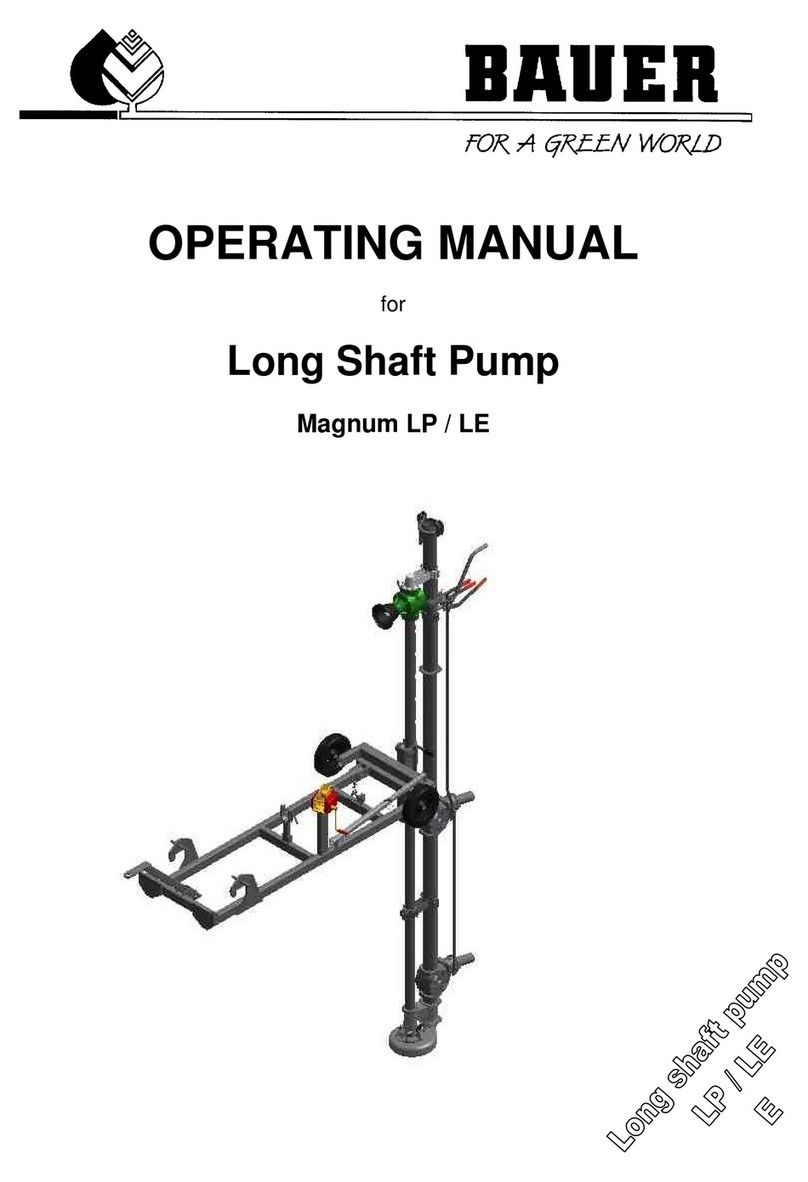
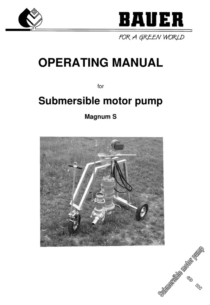
Bauer Magnum SM 540 User manual

OPERATING MANUAL
for
Gear Pumps
Magnum SM 540;
SM 1000 / SM 2000
without and with self-priming unit

II Operating manual for BAUER gear pump
INTRODUCTION
Thank you very much for purchasing a BAUER gear pump!
We are pleased to offer you a BAUER gear pump featuring state-of-art technology and top quality. This
manual describes how to operate and maintain the BAUER gear pump. For reasons of clearness and due to
the many possibilities this manual does not contain everything down into detail. In particular, it cannot possibly
take into consideration every conceivable aspect of operation and maintenance.
If you need further information or if you should be faced with any particular problems for which this manual does
not offer sufficient details please feel free to contact BAUER company at Kowaldstraße 2, A-8570 Voitsberg for
the information you need.
Please note that the content of this operating manual neither constitutes part of nor does it alter any previous or
existing agreement, promise or legal relationship. Any commitment on the part of BAUER is a result only of the
individual purchase contract that also contains the complete and only valid warranty arrangement. Said
contractual terms of warranty are neither extended nor limited by the content of the present operating manual.
All information contained in the present manual is based on the latest product details available at the time of
printing.
BAUER reserves the right to change without prior notice, without assuming any liability!
BAUER gear pumps are designed for safe and reliable operation provided they are operated in compliance with
the present instruction manual. In spite of the simplicity of the pump we therefore request that you read this
manual carefully before putting your BAUER gear pump into operation! All instructions given for handling,
operating and servicing the pump must be strictly observed. Provided these instructions are followed the pump
will operate trouble-free to your full satisfaction for many years!
Non-observance of our instructions may result in injury or equipment damage!
Please make this manual available to your operating personnel. You are kindly requested to state the pump type
and serial number of the gear pump in all inquiries, correspondence, warranty problems or parts orders. These
details are specified on the nameplate.
We hope you will enjoy working with your BAUER gear pump!
This operating manual should be considered an integral part of the gear pump. Suppliers of new and used
pumps are advised to put down in writing that this manual was handed over together with the pump.

Operating manual for BAUER gear pump III
PRODUCT DETAILS
Type designation: Gear pump
Type number: MAGNUM SM 540
SM 1000 / SM 2000
Serial number1:
Dealer: Name:
Address:
Tel./Fax:
Date of delivery:
Manufacturer: Röhren- und Pumpenwerk BAUER Ges.m.b.H.
Kowaldstr. 2
A - 8570 Voitsberg
Tel.: +43 / 3142 / 200 - 0
Fax: +43 / 3142 / 23 0 95
e-mail: [email protected]om
www.bauer-at.com
Owner or operator: Name:
Address:
Tel. / Fax:
Note: Please make a note of the type and serial number of your gear pump and its accessories! Be sure to
specify these details every time you contact your dealer.
Printing date / Version: July 2000
1In all warranty claims and correspondence relating to this machine it is essential to specify the complete serial
number group including all letters. This applies to the machine itself and to any components involved. We cannot
emphasise this point often enough.

IV Operating manual for BAUER gear pump
GENERAL SAFETY INSTRUCTIONS
Symbols and terms
The CE symbol that has to be affixed on the machine by the manufacturer outwardly
demonstrates compliance of the machine with the directives for machines and other relevant
EU directives.
This “Warning” symbol refers to important safety instructions in this manual.
Whenever you see this symbol be aware of possible injury hazards. Read the note
following the symbol very carefully and inform the other operators accordingly.
Non-observance of this instruction may cause damage to or destruction of the
machine or individual components.
It is important to observe this note or condition!
Qualified operators are persons who on account of their training, experience and instruction as well as their
knowledge of relevant standards, rules, precautions to be taken for accident prevention and operating
conditions, have been authorised by the person in charge of plant safety to perform the individual tasks required
and in doing so are able to recognise and avoid potential hazards. Among other things knowledge of first-aid
procedures is also required.
Product liability
As defined by the product liability law every farmer is also an entrepreneur!
According to §9 PHG (Product Liability Law), liability for damage to corporeal things caused by defective
products is expressly excluded. This exclusion of liability also applies to parts not manufactured by BAUER itself
but purchased from external suppliers.
Duty to furnish information
Even if the customer passes on the machine later-on he is obliged to hand the operating manual on to the new
receiver too. The receiver of the machine must be instructed with reference to the mentioned regulations.
Intended use
•BAUER gear pump is built exclusively for normal use in agricultural applications (intended use).
•Any use beyond this normal use is considered non-conforming. Manufacturer is not liable for damage
resulting from such non-conforming use, the sole liability for damage from non-conforming use is with the
user.
•Intended use also includes compliance with the manufacturer’s operating, maintenance and service
instructions.
•The BAUER gear pump may be used and operated only by persons who are familiar with the device and
aware of the hazards involved.
•All relevant rules for accident prevention as well as any other generally valid specifications and regulations
relating to safety, work medicine and traffic law must be strictly observed.
•Unauthorised modification of the machine releases the manufacturer from liability for damage resulting
therefrom.
WARNING!
CAUTION!
NOTE

Operating manual for BAUER gear pump 1
TABLE OF CONTENTS
1 GENERAL INSTRUCTIONS FOR SAFETY AND ACCIDENT PREVENTION.............................................. 2
2 GENERAL........................................................................................................................................................ 4
3 DESCRIPTION ................................................................................................................................................ 5
3.1 Gear pump without self-priming unit......................................................................................................... 5
3.1.1 Suction line........................................................................................................................................ 5
3.1.2 Delivery line....................................................................................................................................... 5
3.2 Gear pump with self-priming unit.............................................................................................................. 5
3.2.1 Suction line........................................................................................................................................ 5
3.2.2 Delivery line....................................................................................................................................... 5
4 PUTTING INTO OPERATION......................................................................................................................... 6
4.1 Gear pump without self-priming unit......................................................................................................... 6
4.2 Gear pump with self-priming unit.............................................................................................................. 9
4.3 Self-vacuum system for centrifugal pumps ............................................................................................ 12
Function and design....................................................................................................................................... 12
5 PUMP SHUT-DOWN..................................................................................................................................... 14
5.1 Gear pumps with and without self-priming unit....................................................................................... 14
6 SERVICE AND MAINTENANCE................................................................................................................... 14
6.1 Mounting instructions for mechanical seal Ø 50 for SM 1000 / SM 2000 and SM 3500 ...................... 15
6.2 Mounting instructions for mechanical seal Ø 45 for pump SM 540 - Part Nr 061 6551 ....................... 19
7 INSTRUCTIONS FOR SAFE AND TROUBLE-FREE PERFORMANCE ..................................................... 21
8 TECHNICAL DATA ....................................................................................................................................... 24
9 FAULT DESCRIPTION.................................................................................................................................. 24
10 CONFORMITY CERTIFICATE.................................................................................................................. 26

2Operating manual for BAUER gear pump
1 GENERAL INSTRUCTIONS FOR SAFETY AND ACCIDENT
PREVENTION
Check the machine for operational safety before every start-up.
1. In addition to the instructions contained in this manual, all specifications generally valid for safety and
accident prevention must be observed!
2. The warning and instruction signs affixed to the machine give very important instructions for safe operation.
Observing them serves your own personal safety!
3. Never put the machine into operation unless all guards and safety devices are completely mounted and in
their proper working position!
4. Acquaint yourself with all equipment components and controls as well as their respective functions before
starting to work. It is too late when the device is already running!
5. The operator’s clothes should fit tightly. Avoid wearing loose clothes!
6. When handling slurry always keep in mind that the gasses produced are highly toxic and extremely explosive
in combination with oxygen. Therefore, open fires, light tests, sparking and smoking are strictly forbidden!
7. Utmost care is required with regard to gasses in slurry and dung channels at open valves to the preliminary
pit, before the main pit, or at cross channels. The same applies to mixing and withdrawal points when
mixers or pumps are running!
8. When handling slurry always ensure sufficient ventilation!
9. Keep the machine clean to avoid fire hazards!
Tractor-driven machines
1. Before starting inspect the area around the machine (Children) ! Make sure your view is unrestricted!
2. Riding on the machine during transport is forbidden!
3. Couple the machine according to instructions and fasten it only at the specified points!
4. Be especially careful when coupling the machine to the tractor or uncoupling it!
5. Always adjust the supports in the proper position when coupling or uncoupling the machine (stability)!
6. Always mount balancing weights properly at the points provided!
7. Observe restrictions pertaining to axle load, total weight, and transport dimensions!
8. Inspect and mount all items required for transport such as lighting, warning signals and possible safety
devices!
9. Mounted or trailed machines as well as balancing weights influence road behaviour, steering and braking
capacity. Therefore make sure that proper steering and braking are possible!
10.Consider the projection and/or centrifugal mass of the machine when driving in curves!
11.It is forbidden to stay in the working range of the machine while it is operating !
12.Keep out of the turning and swivelling range of the machine!
13.Only operate hinged hydraulic frames when nobody is in the swivel range!
14.Externally powered machines (e.g. hydraulic) bear a crushing and shearing hazard!
15.Nobody is allowed between the tractor and the implement unless the tractor is secured by the parking brake
and /or wedges under the wheels!
16.Hinged supports must always be folded up and secured before driving away!
17.Secure the machine and the tractor against rolling!
Tractor-mounted machines:
1. Before a machine is linked to or detached from the three-point linkage, the control device must be shifted to a
position in which unintentional lifting or lowering is impossible!
2. When using the three-point linkage the linkage parameters of both tractor and attached machine must
correspond, if not, they have to be matched accordingly!
3. The three-point linkage bears crushing and shearing hazards!
4. When operating the external control of the three-point linkage never step in-between tractor and the machine!
5. When the machine is in the transport position always make sure that the tractor’s links are always properly
secured on the sides.
6. When driving on the road with the machine lifted the control lever must be locked against lowering!
Trailed machines
1. When a machine is coupled to the drawbar make sure that the coupling point provides sufficient flexibility!

Operating manual for BAUER gear pump 3
Power take-off (applies only to PTO driven machines)
1. It is not allowed to use any other types of PTO drive shafts except those prescribed by the manufacturer!
2. Drive shaft guard tube and guard cone as well as the PTO guard – also on the machine side - must be
mounted and in good working order!
3. When using a PTO drive shaft always observe the specified overlap in transport and working position!
4. Never connect or disconnect the PTO drive shaft unless the PTO is stopped, the engine turned off, and the
ignition key pulled out!
5. Make sure the drive shaft is always connected and secured properly!
6. Attach safety chain to keep the drive shaft guard from rotating with the shaft!
7. Before you turn on the PTO make sure that the selected tractor PTO speed corresponds with the permissible
implement speed!
8. Before starting the PTO make sure that nobody is standing in the danger zone of the machine!
9. Never turn on the PTO when the engine is turned off or during a transport drive!
10.When working with the PTO nobody is allowed near the turning PTO or drive shaft!
11.Warning! The PTO shaft may continue turning due to its centrifugal mass after the PTO has been turned off!
Keep clear of the machine during this time and do not touch until the PTO shaft stands absolutely still!
12.For cleaning, greasing, or adjusting the PTO driven implement or drive shaft, PTO and engine must be
switched off and the ignition key pulled out!
13.Place the disconnected drive shaft on the provided support!
14.When drive shaft has been removed put the guard on the PTO shaft!
15.If a defect occurs repair it immediately before starting to work with the machine!
Hydraulic system
1. Hydraulic system is under high pressure!
2. When connecting hydraulic cylinders and motors, make sure the hydraulic hoses are connected as specified!
3. Before coupling the hydraulic hoses with the tractor’s hydraulic system make sure that the entire hydraulic
system is pressureless both on the tractor and implement side !
4. Inspect the hydraulic lines at regular intervals and replace them immediately in case of defects or ageing.
Replaced hoses must comply with the technical specifications of the implement manufacturer!
5. When looking for leaks use only suitable equipment because of the injury hazard involved!
6. Liquids emerging under high pressure (hydraulic oil) may penetrate the skin and cause serious injuries! An
injured person must see a doctor immediately! Danger of infection!
7. Before working on the hydraulic system the machine must be lowered, the system depressurised and the
engine turned off!
Electric-driven implements
1. All work beyond normal maintenance of the implement should be performed only by a professional
electrician!
2. Defective or broken plugs and sockets must be replaced by a professional electrician!
3. Never pull a plug out of the socket at the flexible electric cord!
4. Extension cables for power supply should be used only temporarily! Never use such lines permanently as a
substitute for the required fixed installations!
5. Flexible lines laid across traffic areas on the farm must have at least 5 m ground clearance!
6. Always turn off the power supply before you do any work on the machine!
7. Check all electric lines for visible defects before you put the machine into operation! Replace defective
cables and do not start the machine before that!
8. Never use electric-driven implements in damp situations or locations exposed to fire hazard unless they are
adequately protected against moisture and dust!
9. Covering electric motors may cause heat concentration with high temperatures which could destroy the
operating equipment and cause fires!

4Operating manual for BAUER gear pump
Hand-operated devices (valves)
1. Because of the slurry gasses produced in the lines, no slurry is allowed to remain in closed pipelines –
bursting hazard!
2. Lay the pipelines with sufficient inclination and make sure that the selected closing order of valves allows all
lines to be drained completely!
3. Protect the valves against unauthorised handling!
4. If a valve gets jammed do not apply force! Use only the operating levers supplied with the implement!
5. Observe the permissible maximum operating pressure of valves and pipelines when pumps are operated!
6. Service only when the tanks are empty!
Maintenance
1. Never perform any maintenance, service or cleaning work or fault elimination steps unless the drive is turned
off and the engine is standing still!
2. Check proper fit of all nuts and bolts regularly and tighten them, if necessary.
3. If maintenance work is required on the lifted machine always secure it by means of appropriate supports!
4. When exchanging tools with cutting edges always use proper tools and wear safe protective gloves.
5. Dispose of oil, grease and filters according to local laws and regulations!
6. Always turn off power before working on the electric system!
7. Before electric welding on the tractor and mounted machines the generator and battery cables must be
disconnected!
8. Spare parts must meet manufacturer’s minimum technical specifications! This is the case for instance with
original spare parts for instance!
2 GENERAL
Apart from the mechanical hazards resulting from moving or pressurised parts, the
operation of slurry handling devices may also involve danger resulting from slurry
gasses. These gasses (carbon dioxide CO2, ammonium NH3, hydrogen sulphide
H2S, methane CH4) could cause poisoning as well as explosions. When operating in
particular mixers, agitators, recirculation systems, stirring nozzles and slurry aeration
systems one must always make sure that no gasses are allowed to penetrate into
the stable from outside tanks (installation of siphon or stop valve). When slurry is
handled inside the stable area sufficient forced ventilation in the stable area must be
secured.
BAUER products are designed and manufactured carefully and subject to a system of continuous quality control.
MAGNUM slurry pumps fully meet the requirements of the agricultural practice. They are best suited for
delivering all kinds of slurries from thin liquid manure to viscous mixtures containing solids such as straw, fibres
or clots. A special chopper guarantees trouble-free performance without blockages. Short set-up times, easy
handling and maximum performance reliability are further advantages of this pump series. Pump drive is
mechanical from a drive shaft onto the PTO input shaft of the pump’s gearbox.
Although the pump is simple in design you should study this manual carefully and strictly observe all operating
and service instructions contained . On this condition your slurry pump will operate to your full satisfaction for
many years!
Make this manual available to all operators handling the equipment. Serial number and pump type are stamped
in on the nameplate. Please specify these data in your inquiries, correspondence, warranty matters and parts
orders. We warrant for this pump according to our General Terms of Sale.
WARNING!

Operating manual for BAUER gear pump 5
3 DESCRIPTION
MAGNUM slurry pumps are designed with a special chopper on the suction side. This chopper guarantees
trouble-free operation also if the pumped slurry contains solids like straw, fibrous materials, and clots or sludge
up to not more than 12 %. Maximum permissible slurry temperature: 80°C.
3.1 Gear pump without self-priming unit
This pump mainly consists of the spur gear and the volute housing with impeller and cutting flange and the
chopper assembly. Power is transmitted directly from the tractor and a drive shaft to the gearbox of the pump.
The pump is preferably mounted on a pump trolley and hitched to the tractor’s toolbar. While the pump is
operating the drive shaft should be articulated as little as possible to ensure easy running and longer life of
pump, gearbox, and drive shaft. Volute housing and gearbox are sealed off by a mechanical seal.
3.1.1 Suction line
The suction line must be equipped with a manual, lever operated foot valve. Suction line and pump must
be filled with water before starting up the system.
3.1.2 Delivery line
We recommend to mount a stop valve in the delivery line. This is an advantage if pump operation is interrupted
only for a short while. Closing of the stop valve and the foot valve will save renewed filling of pump and suction
line when pumping is continued.
3.2 Gear pump with self-priming unit
This pump is a self-priming gear pump as described under 3.1 equipped with an additional attachment.
3.2.1 Suction line
Being equipped with a self-priming unit, a standard spiral suction hose and suitable fitting pipe with a coupled
funnel can be used as a suction line.
3.2.2 Delivery line
It is absolutely necessary to install a stop valve in the delivery line. This valve must be closed during the priming
process, otherwise slurry would be sucked in through the delivery line and the suction line would not be filled.

6Operating manual for BAUER gear pump
4 PUTTING INTO OPERATION
4.1 Gear pump without self-priming unit
Check oil level in the gearbox and in the oil reservoir before every start!
Position the pump as close to the pumped medium as it is safe to do so.
•Couple the suction line with the pump’s suction connection
and close the foot valve.
•Always use the shortest possible suction pipe
•Check that all connections are air-tight and that the
suction hose is in good condition
•Always ensure the pumped medium is homogeneous –
DO NOT OVER MIX! Air in the slurry affects performance
& can cause serious pump damage by cavitation.
•Difficult suction conditions can seriously affect the
performance of the pump and lead to cavitation
WARNING!

Operating manual for BAUER gear pump 7
•Fill up pump and suction line completely with water
through the delivery socket.
•Connect the delivery line and close the stop valve in the
delivery line.
•Connect tractor and pump by means of the drive shaft.
Use drive shafts with shear pin couplings only!
Refer to separate drive shaft manual for length adjustment, profile tube overlap and
maintenance!
Do not raise or lower pump on tractor hydraulic linkage while PTO shaft is turning
WARNING!
WARNING!

8Operating manual for BAUER gear pump
•Engage the PTO, run up at low engine speed, and open
the foot valve of the suction line.
•Slowly open the stop valve and keep the PTO speed
constant until the pumped medium is distributed by the
spreading device at the end of the delivery line.
•Do not fill the delivery line too quickly. Cavitation can occur
under these conditions & the pump can become damaged
very quickly
•Increase PTO speed gradually until the desired
operating pressure and discharge rate are reached.
NOTE! The pump does not always need to be operated at
maximum operating speed.
Always choose a speed that is just sufficient to obtain the
desired performance.
Failure to this instruction could increase fuel consumption,
pump wear-out rates and possibly damage other parts & the
pumping system
NEVER WORK THE PUMP IN CAVITATION !

Operating manual for BAUER gear pump 9
4.2 Gear pump with self-priming unit
Check oil level in the gearbox and in the oil reservoir before every start!
Position the pump as close to the pumped medium as it is safe to do so.
•Couple the suction line with the pump’s suction
connection.
•Always use the shortest possible suction pipe
•Check that all connections are air-tight and that the
suction hose is in good condition
•Always ensure the pumped medium is homogeneous
– DO NOT OVER MIX! Air in the slurry affects
performance & can cause serious pump damage by
cavitation.
•Difficult suction conditions can seriously affect the
performance of the pump and lead to cavitation
•Always fill up the pump with about 3 litres of water
through the side branch of the delivery socket.
WARNING!

10 Operating manual for BAUER gear pump
•Couple the delivery line and close the stop valve in the
delivery line.
•Connect tractor and pump by means of the drive shaft.
Refer to separate drive shaft manual for length adjustment, profile tube overlapping
and maintenance!
•Make connection between side branch and tank (quick
coupling).
•Open stop valve in the branch.
•Engage the PTO and run the tractor at about 300 rpm drive speed.
WARNING!

Operating manual for BAUER gear pump 11
•Shift lever to position 2 (lift up) and hold it until the pump is
filled.
If the pump is not filled after this procedure check all connections and hoses for
absolute tightness. A trapped ball or a rubber that has not been positioned correctly
could be another cause for failure. Leave the oiler open to ensure optimum
performance of the self-priming unit
•Close the stop valve in the branch.
•Slowly open the stop valve in the delivery line and
keep the PTO speed constant until the pumped
medium is distributed by the spreding device at the
end of the delivery line.
•Do not fill the delivery line too quickly. Cavitation can
occur under these conditions and the pump can
become damaged very quickly.
•Increase PTO speed gradually until the desired operating pressure and discharge rate are reached.
•Increase PTO speed until the desired operating
pressure and discharge rate are reached.
NOTE! The pump does not always need to be operated at
maximum operating speed.
Always choose a speed that is just sufficient to obtain the
desired performance.
Failure to this instruction could increase fuel
consumption, pump wear-out rates and possibly damage
other parts & the pumping system
NEVER WORK THE PUMP IN CAVITATION !
WARNING!

12 Operating manual for BAUER gear pump
Do not engage or disengage PTO abruptly to avoid shocks and pressure
hammers.
4.3 Self-vacuum system for centrifugal pumps
Function and design
WARNING!
evacuation pump
separator/trap
return valve
lever
spring (not shown)
centrifugal pump
ball valve
(not shown)
oil tank

Operating manual for BAUER gear pump 13
The centrifugal pump is not able to take in the medium (water or manure) itself – this is done by the self-
vacuum device.
In the suction pipe, negative pressure is generated by means of the evacuation pump; thus the pipe and the
pump are filled with the medium.
Manure must by no means get into the evacuation pump! This is achieved by means of a valve system in the
separator/trap.
Do not switch one valve ball for the other (they are the same size, but are different in weight!).
With the mechanic self-vacuum device, the evacuation pump is driven together with the centrifugal pump by
means of a V-belt. For suction purposes, the belt is tensioned by means of a hand lever (V-belt drive not shown
in drawing).
Once the vacuum pipe is filled, the valve ball closes the separator and negative pressure is created on the intake
side of the evacuation pump (note the difference in the sound the pump makes).
The imminent end of the suction process is indicated by movements of the vacuum hose.
Release the belt tightener. The centrifugal pump starts to deliver.
The return valve in the pressure line opens (only slightly at first). After 10 to 15 seconds, the pump should have
built up full pressure and the return valve opens entirely.
The lever (on the outside of the return valve) is only used for indicating the operating condition. The return valve
need not be pressed closed with the lever during the suction process.
The spring supports closing of the return valve after the centrifugal pump has been switched off.
With the hydraulic self-vacuum device the centrifugal pump need not (should not) run during the suction
process. The self-vacuum system can be operated directly from the tractor.
Near the end of the suction process connect the centrifugal pump and switch the evacuation pump off. (Do not
let the evacuation pump continue to run, this would only cause unnecessary heating and wear).
After the pumping process has been concluded, the return valve closes and the vacuum line remains filled (!).
At the next start, there is no need to switch on the evacuation pump – the centrifugal pump starts delivering
immediately.
For emptying the intake line open the ball valve at the separator/trap.
Operating instructions:
•Make sure the oil tank of the evacuation pump is filled.
•Close the ball valve (on the separator/trap) before the suction process starts
Error / - Possible causes / ð
ðð
ðRemedies / Comments
The (hydraulically driven) evacuation pump does not rotate.
- Hydraulic lines (on the tractor) incorrectly connected
ðConnect lines anew
Do not operate the evacuation pump with incorrect direction of rotation, as this would prevent lubrication.
This is the reason why there is a return valve on the hydro-motor.
The (hydraulically driven) evacuation pump rotates too slowly; the suction process takes too long
- Tractor speed too low; too little hydraulic oil delivered
ðIncrease tractor speed
Avoid overspeeding of the hydraulic motor! (The maximum speed of 1550 rpm corresponds to an oil flow
of 20 l/min ). This is why there is a throttle on the hydraulic motor to limit the amount of oil and thus the
speed. If, however, there is not enough oil provided by tractor hydraulics, the hydro motor will not reach
full speed.

14 Operating manual for BAUER gear pump
The evacuation pump does not take anything in – the lever on the return valve can be moved easily
-(a) leakage in the intake line
-(b) intake line clogged
ðre (a) Check intake line and seals
ðre (b) Rinse separator/trap
When the evacuation pump is taken into operation, the return valve is closed because of the negative
pressure – the lever on the return valve can only be moved with great effort. In case of leakage or
clogging, no negative pressure can be built up.
Note: If the intake hose is only pushed through the surface scum of the manure cistern, or if the
content of the cistern is not properly mixed, solid components may be taken in that clog the
intake line.
The suction process takes very long and the centrifugal pump cannot deliver any more; the water column (liquid
manure) breaks down:
-(a) slight leakage in the intake line
-(b) suction height too high; medium too viscous
ðre (a) Check intake line and seals
ðre (b) Reduce suction height and/or add water
The evacuation pump is slightly more powerful than the centrifugal pump. If there are slight leakages or if
the suction head is too high, the evacuation pump may be able to fill the intake line, but the centrifugal
pump is no longer able to delivery the medium.
Note: If the liquid manure is very viscous, only half the suction height compared to water can be
achieved.
5 PUMP SHUT-DOWN
5.1 Gear pumps with and without self-priming unit
Close the stop valve in the delivery line and lower the speed until the engine stops. Then disengage the PTO.
Now open the stop valve slowly allowing the liquid still remaining in the pipes to flow back into the pit and release
overpressure.
If only a short interruption is planned we recommend to close the valve. This will save renewed filling of the
pump.
If the pump is moved to a different position the counter-pressure must be released as described above When
the pump is uncoupled sufficient liquid remains in the pump and it is not necessary to fill it up again for instance
with water before putting the pump into operation again.
6 SERVICE AND MAINTENANCE
It cannot be emphasised often enough how much proper service and maintenance influence performance
reliability and service life of a machine.

Operating manual for BAUER gear pump 15
The pump and all its accessories should be cleaned immediately after use. As long
as the slurry has not dried up it can easily be rinsed off with water. Shortly rinse the
pump at low speed with clear water fed through the rinsing connection after every
use.
The best way to clean the interior of pipes and fittings is to pump water through the system for several
minutes with the pump running at PTO idle speed.
•The pump should be stored in a weather-protected place, preferably in a shelter. In areas where frost is
likely during the winter season the pump housing must be drained completely by the impeller to spill out the
remaining water.
•The gearbox oil should be exchanged for the first time after 50 and after that every 2000 hours of operation,
but at least once a year.
•The mechanical seal is made of high-strength materials. The oil reservoir provides it with liquid (hydraulic oil
– e.g. 0.4 l Shell Tellus S22) so the seal will not even be destroyed if the pump runs dry for a short while.
•Functional check-up of the mechanical seal is limited to visual inspection of the oil level in the oil reservoir. If
liquid emerges from the oil reservoir while the pump is running or if the predetermined oil level cannot be
reached, the sealing must be checked for damage (foreign objects).
•Always replace both rotary and stationary seal ring at the same time.
•We recommend to rinse the pump with water before it is dismantled. In doing so, foreign objects can be
washed out and the mechanical seal would be tight again.
•Observe local laws and regulations when disposing pumps and pump components after repairs and service
or when a pump is withdrawn from service. This applies in particular to residual slurry in the pump body.
6.1 Mounting instructions for mechanical seal Ø 50 for SM 1000 / SM 2000 and
SM 3500
Accessories for mechanical seal assembly
Loctite 242 for securing the threaded bolts of the mechanical seal.
Adhesive tape for covering the sharp edges of the key groove.
Molykote for lubricating the sliding faces of the O-rings.
Allen key for threaded bolts of the mechanical seal.
Knife for cutting the adhesive tape.
WARNING!

16 Operating manual for BAUER gear pump
Assembly kit for adjustment of the functional length of the mechanical seal.
Sleeve
Washer
Nut
Do not forget to insert the anti-rotation lock pin of the stationary seal ring in
the seat.
To protect the O-ring of the rotating element, cover the sharp edge of the key groove, only up to the end
of the cone.
Spray the O-rings with Molykote to reduce friction.
(water, alcohol, or silicone grease are suitable, too).
Mount the stationary seal ring
Groove and anti-rotation lock pin must be in alignment.
Preparing the rotating collar.
Remove the threaded bolt
This manual suits for next models
2
Table of contents
Other Bauer Water Pump manuals
Popular Water Pump manuals by other brands

Pentair
Pentair AURORA 654A Instruction and repair manual

Oase
Oase Aquarius Eco Expert operating instructions

PSH Pools
PSH Pools MICRO.2 Series manual

Becker
Becker VARIAIR DTLF 2.500/0-400 operating instructions

Antares
Antares P.023 Installation and instruction manual

Eaton
Eaton 26 Series Repair Information

Wilo
Wilo Atmos PICO Installation and operating instructions

Stokes Microvac
Stokes Microvac 412H-11 instruction manual

Grundfos
Grundfos SP Safety instructions and other important information

Emerson
Emerson YARWAY CONDENSAVER Series Installation, operation and maintenance instructions

Lavor
Lavor EG-M 3800 instruction manual

GPI
GPI M-180S Product owners manual