BAUMAN Hay Fluffer Tedder User manual
Operator’s Manual
Manufactured in Canada

1
Contents
Introduction:........................................................................................................................................................................... 2
Dealer Information:................................................................................................................................................................2
General Information:..............................................................................................................................................................3
Attachment / Setup / Adjustment:........................................................................................................................................3
Transporting the Machine: ................................................................................................................................................ 3
Field Setup:.........................................................................................................................................................................3
Height Adjustment:............................................................................................................................................................ 4
Maintenance:..........................................................................................................................................................................4
Safety:.....................................................................................................................................................................................5
Safety Labels:...................................................................................................................................................................... 5
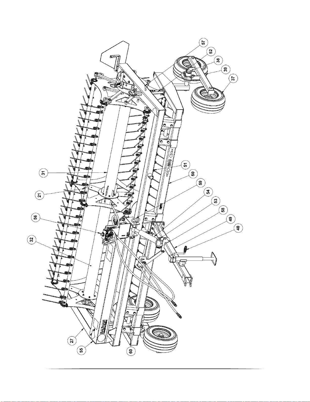
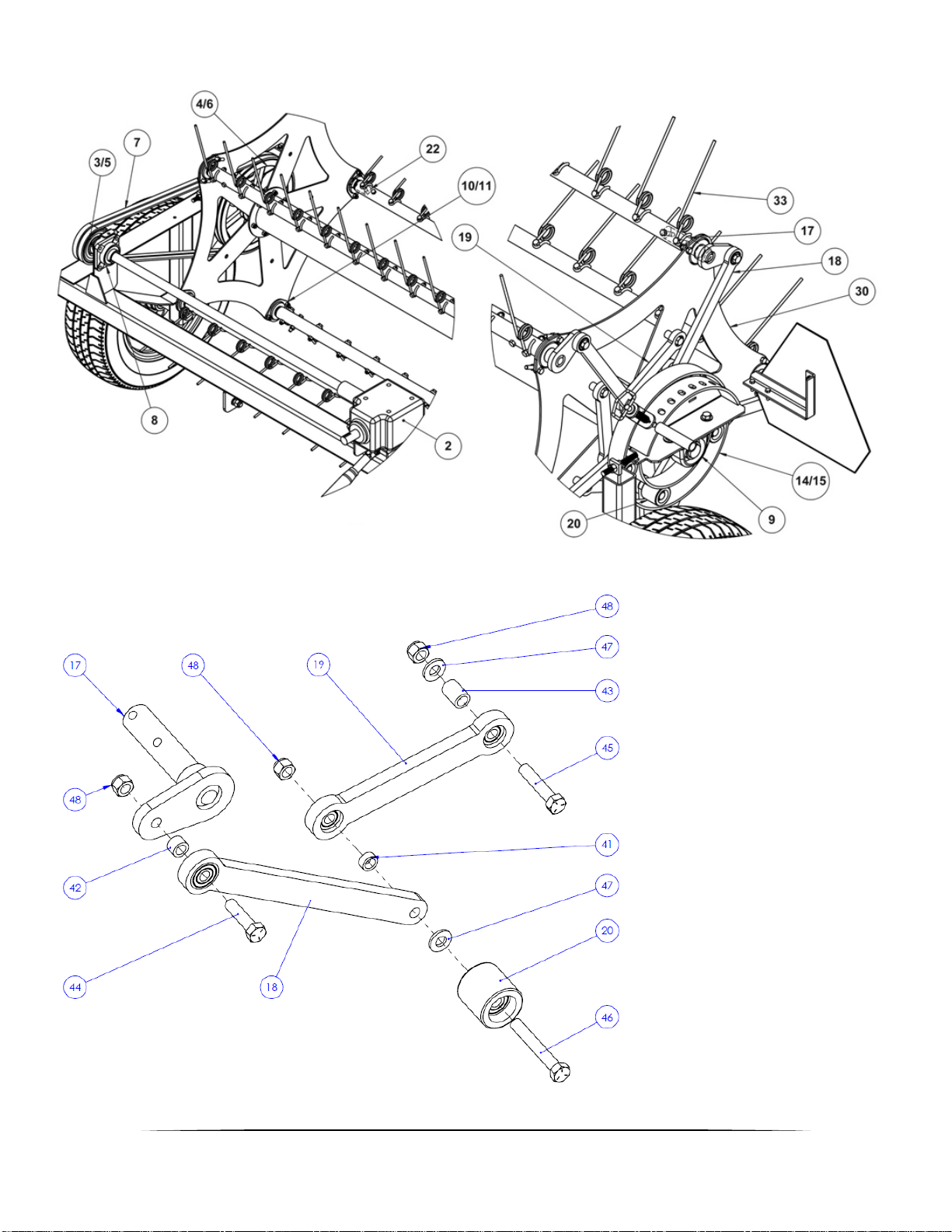
Parts List: ................................................................................................................................................................................ 6
Parts Breakdown:...................................................................................................................................................................8
Turnbuckle Lift Tedder .......................................................................................................................................................8
Hydraulic Lift Breakdown...................................................................................................................................................9
Belts & Reel Components.................................................................................................................................................10
Operator Notes:....................................................................................................................................................................11
Printed 08/09/2019

2
Introduction:
Congratulations on your purchase of a Bauman Hay Fluffer Tedder. Thank-you for choosing a quality
product from Bauman Manufacturing Ltd. We strive to build a quality piece of equipment and with a
little care and maintenance this machine will work for you for many years.
In this manual we make an effort to get you acquainted with the machine so you can achieve
maximum performance. Correct usage of the machine also includes observance of the factory's
preparation, operation and maintenance instructions. This operator's manual will help you understand
and use the many features on the machine and contains information which explains how to use and
maintain the machine so that you utilize it’s full potential. All the information, illustrations and technical
specifications in this manual are based on the latest product information at the time of printing. Please
note that it is within our rights to make changes and improvements to our equipment without updating
the equipment that was manufactured before the change took place. Bauman reserves the right to
change design and specifications and/or to make additions and improvements to the product without
notice.
Dealer Information:
Please take a few minutes to fill out the area below. This information will be valuable to you when
ordering parts from your dealer later.
Dealer Name:_________________________________________
Dealer Phone Number: _________________________________
Model Number: _______________________________________
Serial Number: _______________________________________
Date of Purchase: _____________________________________
The tedder's serial number can be found on the main frame of the machine close to the gearbox
mount. Please use this number when requesting service, seeking information, or ordering parts.
Please record this number in this owner’s manual.

3
General Information:
The Bauman Hay Fluffer Tedder is designed to gently lift and release hay with minimum leaf damage.
This machine is designed to fluff hay, forage crops or straw only. Bauman will not cover under
warranty a tedder that has been used outside of these crops. The operator must read and understand
all the information in this manual to make sure that you operate the machine correctly and thus avoid
unnecessary risk of accidents and breakdowns. Always stop the tractor engine before you adjust,
lubricate, or repair the machine. Remember to remove the ignition key to make sure no one starts the
tractor while you are repairing the machine. Never under any circumstances let anyone get close to or
stay close to the machine while in operation.
Attachment / Setup / Adjustment:
Always use a tractor that is at least twice the weight of the tedder. When attaching to the draw bar
always use a draw pin with a safety clip to avoid the draw pin bouncing out and the tedder
disconnecting from the tractor. When attaching the PTO shaft to the tractor make sure that the PTO
yoke push pin is engaged properly. REMEMBER!! The power take-off shaft’s safety shield must be
undamaged when operating the machine. If necessary, change the safety shield.
Hydraulic lift and/or drive: attach hoses to the hydraulic outlets. Ensure proper hose engagement and
the hoses are secured away from the drawbar or 3-point hitch arms and that the hoses are in good
condition and free of damage. (note: Never run your hand over a hose that you suspect may be
damaged as serious injury may occur). Attach a safety chain to the machine.
Transporting the Machine:
Never allow riders on the tractor or on the machine. Remain fully aware of the width of the tedder in
relation to objects you are passing. Always follow local traffic laws regarding the transporting of farm
equipment. Be sure the slow-moving vehicle sign is always visible. Never travel on the road at night.
Your machine is not equipped with lights.
For machines with hydraulic reel lift ALWAYS put the two mechanical stops to the top position for
transporting as see in Figure 2 - Turnbuckle and Hyd. Lift Stop. This will set the reel to maximum height
to reduce chance of tines being damaged.
Field Setup:
Do not make any adjustments to the tedder unless the tractor is shut off
and the PTO/Hydraulic is disengaged. To obtain optimum hay fluffing,
tractor engine RPM should range from 1200–1500 and travel speed
from 5-7 mph. Going over recommended engine RPM may cause
damage to the machine and void your warranty. To obtain optimum hay
fluffing on the hydraulic drive version; the tractor engine RPM should be
1500 to 1700 RPM to ensure maximum oil flow to the tedder & set the
hydraulic flow valve to the middle position (#5) and adjust speed + or –to
achieve the desired reel speed. NOTE- optimum desired operating speed for the hydraulic or PTO
drive version requires the reel speed to be approximately 20% faster than ground speed. To adjust
the tooth or tine angle, disengage the PTO/hydraulics and shut off the tractor, then on the right-hand
side of the machine lift spring pin and move lever to the desired location. The + symbol will move the
tooth to a more aggressive position that will throw the crop higher and the - symbol will do the
opposite.
Figure 1 - Tine angle adjustor

4
Height Adjustment:
To adjust the height of a turnbuckle lift tedder, you must disengage
the PTO shaft, shut off the tractor, and wait until the machine comes
to a complete stop. Now rotate the turn buckle under the PTO shaft
to change the height of the reel. Turnbuckle is equipped with a “lock”
or “jam nut” and it is recommended that the jam nut be tightened by
tapping with a hammer handle once the desired height is achieved.
To adjust the height of a hydraulic lift tedder, adjust the reel stops
(located on the reel support arms) using one of the three-hole
positions to achieve the proper tine to ground clearance.
We recommend 1-2" clearance between the ground and the bottom of the tooth. While it is
impossible to eliminate all contact with the ground, try to keep it to a minimum as this not only wears
the tines but contaminates your hay with dust and creates unnecessary wear on your other harvesting
equipment.
Maintenance:
Warning: When repairing, maintaining and cleaning the machine, it is particularly important to
be aware of safety precautions. Park the tractor (if connected) and machine and follow all
precautionary measures.
Important: Bolts on your new machine must be tightened after 2 hours of working.
As is the case with any piece of equipment periodically check for loose bolts and nuts as paint
and parts settling after the initial vibrations are common and can cause bolts or nuts to come
loose. Check the following parts frequently: tines, bat arms, cam arms, guards, pulleys, bearings,
wheels, etc. Grease the bearings every 8 hours. You should check the gearbox at least once a year.
If necessary, add to the proper level with gear oil. Remember when adding gear lube, the machine
must be in a horizontal position. The gearbox should have approximately two inches of gear lube in it.
It is important to keep the drive belts tight. At each end of the reel there are pillow block bearings,
loosen the bolts 1 round only. Tighten the adjustment bolts (uniformly on both sides) until the belts
are tighten to the proper tension, and then retighten the bearing bolts.
Figure 2 - Turnbuckle and Hyd. Lift Stop

5
Safety:
Always stop the tractor engine before you adjust, lubricate, or repair the machine. Remember to
remove the ignition key to make sure no one starts the tractor while you are repairing the machine.
Below you will find the precautions of which the operator must have thorough knowledge:
- Always read and obey warning/danger labels.
- The operator must make sure before operating machine that all guards and grills are in place and
attached properly.
- Stay clear from all moving parts! Rotating parts can cause serious injury.
- Never allow riders on the tractor or the tedder.
- Remain fully aware of the width of the tedder in relation to objects you are passing.
- Do not start the tractor before all persons are a safe distance from the machine.
- Check that all the safety shields are properly in place.
- Never operate the machine wearing loose garments; loose garments could be pulled in by a
movable part of the machine.
- Always use statutory vehicle lights and safety markings as required by law when using public roads
or when driving in the dark.
- Never stand close to the machine when in operation.
Only use original spare parts.
- Do not use the machine for any other kind of work than that for which it has been constructed. The
machine must be used for the purpose for which it had been manufactured.
- Beware of humans and animals standing near the machine.
- The operator has the responsibility not to get himself or others in danger during work.
Safety Labels:
The danger labels on our equipment are for your safety, and for those people that are close to the
machine. Always read and obey warning/danger labels. The operator must make sure before
operating machine that all guards and grills are in place and attached properly.
The decals shown below are some of the decals on your machine. These safety decals are for the
safety of yourself and others and must be obeyed at all times. If these labels or decals are missing or
become faded, you the owner are responsible to have them replaced. Please contact your dealer for
replacements.

6
Parts List:
Code
Description
Qty
Req
7'
Qty
Req
9'
1
5910 600
PTO SHAFT
1
1
2
5910 800
GEAR BOX
1
1
3
2MBL4.9
PULLEY
1
1
4
2B13.6
PULLEY
1
1
5
QT-104
BUSHING 1-1/4”
1
1
6
SK-106
BUSHING 1-3/8"
1
1
7
BLTBX091
VEE BELT
2
2
8
UCF 206-20
BEARING 1-1/4”
1
1
9
UCP 207-22
BEARING 1-3/8”
2
2
10
SA 206-20
INSERT 1-1/4”ELC
15
15
11
FL6-Z
FLANGETTE 2 BOLT
30
30
12
5910 461
BEARING TIGHTENER
1
1
13
5910 460
CAM GAUGE
1
1
14
5910 402
CAM ONLY
1
1
15
5910 450
CAM INNER HUB
1
1
16
5910 405
SPRING PIN LATCH
1
1
17
5910 441
CAM ARM / BAT PIN
5
5
18
5910 420
CAM ARM LONG
5
5
19
5910 430
CAM ARM SHORT
5
5
20
5910 410
CAM ROLLERS
5
5
21
5910 306
CENTER BAT COUPLER
5
5
22
5910 305
DRIVE END BAT PIN
5
5
23
ETLP19076
HITCH PIN 3/4" X 4 1/2" (66560)
1
1
24
384505
RED HITCH PIN 3/4" x 6-1/2"
1
1
25
ETL2811406H
TOP LINK 3/4" CAT 1
1
1
26
ERB251951
TOP LINK BUSHING CAT 1
2
2
27
5910 500
GUARD BELT & PULLEY
1
1
28
5710 501
GUARD GEAR BOX & CROSS SHAFT
1
28
5910 501
GUARD GEAR BOX & CROSS SHAFT
1
29
5710 310
REEL BAT 41.25"LONG
10
29
5910 310
REEL BAT 53.25"LONG
10
30
5910 320
REEL SPIDER
3
3
31
5710 330
REEL TUBE W/FLANGE CAM END
1
31
5910 330
REEL TUBE W/FLANGE CAM END
1

7
Parts List Continued:
Code
Description
Qty
Req
7'
Qty
Req
9'
32
5710 340
REEL TUBE W/FLANGE DRIVE END
1
32
5910 340
REEL TUBE W/FLANGE DRIVE END
1
33
5910 300916ST
SPRING TINE TOOTH
100
130
34
5710 200
TEDDER FRAME 7'
1
34
5910 200
TEDDER FRAME 9'
1
35
5910 100
TEDDER HITCH
1
1
36
5910 700
WHEEL
2
2
37
95-060
TANDEM WHEEL
4
4
38
H 02500 1 5 450
WHEEL HUB
2
2
39
5910 TANDEM
TANDEM KIT (LEFT & RIGHT)
2
2
40
TJP-2001S-B
2000LBS JACK
1
1
41
5910 422
½” x ¾” x 0.3125” LONG BUSHING
1
1
42
5910 421
½” x ¾” x 0.5” LONG BUSHING
1
1
43
5910 431
½” x ¾” x 1.06” LONG BUSHING
1
1
44
02301 008 200
½” OD x 2” LONG HEX BOLT
1
1
45
02301 008 208
½” OD x 2.5” LONG HEX BOLT
1
1
46
02301 008 308
½” OD x 3.5” LONG HEX BOLT
1
1
47
02307 008-SAE
½” ID SAE WASHER
2
2
48
02312 008 STOVER
½” STOVER NUT
3
3
49
5910 100L
HITCH
1
1
50
5710 201L
LOWER FRAME ASSEMBLY
1
50
5910 201L
LOWER FRAME ASSEMBLY
1
51
5710 202L
REEL FRAME
1
51
5910 202L
REEL FRAME
1
52
5910 203L
STOP
2
2
53
5710 204L
LOWER CYLINDER PIN
1
1
54
5710 220L
CYLINDER ASSEMBLY
1
1
55
5710 502
CROSS SHAFT SHEILD HYD.
1
55
5910 502
CROSS SHAFT SHEILD HYD.
1
56
5710 HYD
CONVERSION
HYDRAULIC MOTOR & CONTROL
1
1
57
EBHP12076
½” BENT PULL PIN
2
2
58
ELP11045
7/16” LYNCH PIN
1
1
59
ERHHP25254
RED HITCH PIN 1” x 7-1/2”
1
1
60
UCPA 208-24
BEARING 1-1/2”
6
6

8
Parts Breakdown:
Turnbuckle Lift Tedder
9
Hydraulic Lift Breakdown
10
Belts & Reel Components
Cam Components, Exploded View:
Note Item 43 is shown for reference only, this component is welded to the reel assembly.

11
Operator Notes:
Table of contents


