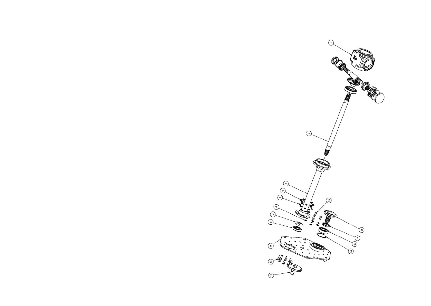
Winton WRT Series User manual

Owner Manual
Winton Rotovator
WRT Series
IMPORTANT: Read all instrucons before using this aachment
2
Congratulations on the purchase of your new attachment!
Before you get started, we have provided a helpful space to jot down a
few important details:
This manual should be considered a permanent part of this attachment
and therefore should remain with it even if the attachment is
subsequently sold.
The manufacturer continually seeks advancements in its product design
and quality. Therefore, while this manual contains the most current
product information available at the time of printing, there may be minor
discrepancies between your attachment and this manual.
If you have any questions concerning this manual, please consult your
local dealer.
Model number: WRT125 / WRT150
Serial number:
Date of purchase:
Factory reference: IGN125 / IGN150

3
Safety Information
Before installation/maintenance, ensure both tractor and
attachment are stationary, with the hydraulic lift system in a neutral
position and the ignition key removed. Read and understand this
manual fully before operating machinery. Failure to follow all safety
standards can result in severe injury or death.
1. This attachment is for use with compact tractors only. Only use for its
indicated purpose. Do not use to transport personnel or livestock.
2. Never consume alcohol/drugs while operating machinery.
3. Always wear protective gloves and ear/eye protection, tie back long
hair. Do not wear loose clothing.
4. Keep spectators at a safe distance. Check the operating area is clear
of debris that can cause damage.
5. Do not run the engine in an enclosed area. Do not leave machinery
unattended while operating. Do not touch moving parts.
6. Regularly check/tighten all bolts, nuts and screws (and those securing
blades). Regularly check condition of blades, belts and wearing parts.
Immediately repair/replace any damaged or worn parts.
7. Ensure all safety guards are in good condition and securely in place.
8. Always keep the PTO output from the tractor at 540 rpm. Reduce the
speed when working on hillsides/rough terrain. Stop the engine
immediately if excessive vibration occurs.
9. Switch o the PTO if transporting attachment to a dierent site.
10. Switch o the engine before any maintenance. Allow attachment to
cool before performing checks. Pay attention to any sharp/pointed
parts, and use suitable tools when servicing.
11. Regularly check condition of attachment (and service). Always repair/
replace any defective parts. Keep all safety signs clean and legible.
Replace missing/illegible signs.
12. Regularly clean the attachment. Check for/clear any entangled
material around moving parts.
13. Do not modify the attachment as this may impair the operation and
overall safety.
14. Re-coat any damaged paintwork to prevent corrosion.
15. Store attachment in a dry area. Ensure it is supported/stable.
4
Safety Information (Continued)
Attachment Pre-use Checks
Upon receipt of attachment, and again within the rst 4 hours of use:
1. Check/tighten all bolts, nuts and screws (and those securing blades).
2. Check the tension of any belt(s), and adjust if required.
3. Apply grease to grease points if necessary.
Tractor & Attachment Installation Checks
1. Before installing the PTO shaft, both tractor and attachment should
be stationary, with the ignition key removed.
2. Check engine oil level, top-up if required but do not overll.
3. Check attachment is securely attached to tractor with secure pins on
linkage mounting pins. Attach chain of PTO shaft, to a secure point
on the tractor.
4. Check tractor PTO turns freely, and the attachment’s PTO drive shaft
can extend easily. Apply grease to PTO drive shaft.
5. Add extra weights to front of tractor (or wheel weights) if required.
6. Ensure all safety guards/doors/covers are securely in place.
7. Keep spectators at a safe distance before operating machinery.
Post-use Regular Checks
Be aware components can be hot after operation. Allow attachment
to cool before performing checks. Pay attention to any sharp/
pointed parts, and use suitable tools when servicing.
1. Regularly check/tighten all bolts, nuts and screws (and those securing
blades). Regularly check condition of blades, belts, wearing parts,
PTO shaft and safety guards. Immediately repair/replace any
damaged or worn parts.
2. Regularly clean the attachment, check for/clear any entangled
material around any moving parts. With the PTO shaft detached, turn
the shaft by hand to ensure there are no obstructions.
3. Regularly check/clean rotor and roller bearings, apply grease if
required. Replace bearings if oil seals are damaged.

5
Safety Information………………………………………………………………………..page 3-4
Specications…………………………………………………………………………………..page 6
Installation.…………………………………………………………………………………..page 7-8
Blade Replacement………………………………………………………………………….page 9
Gearbox Oil Change & Check…………………………………………………………page 10
Gearbox Reservoir Oil Change……………………………………………………….page 11
Rear Guard Adjustment…………………………………………………………………page 12
Tilling Depth Adjustment……………………………………………………………….page 13
Servicing & Maintenance……………………………………………………………….page 14
Attaching & Resizing PTO Shaft……………………………………………………..page 15
Parts Diagram 1…………………………………………………………………………….page 16
Parts List 1………………………………………………………………………………..page 17-18
Parts Diagram 2…………………………………………………………………………….page 20
Parts List 2……………………………………………………………………………………..page 21
Troubleshooting…………………………………………………………………………….page 22
Winton Product Warranty………………………………………………………………page 23
Contents
6
Model: WRT125 WRT150
Weight: 285kg 320kg
Max. tilling depth: 15cm 15cm
Working width: 125cm 150cm
PTO turning speed: 540 RPM 540 RPM
Blade rotor speed: 205 RPM 205 RPM
No. of blades: 36 42
Recommended tractor HP: 25-40 hp 30-55 hp
Width: 150cm 175cm
Depth: 100cm 100cm
Height: 100cm 100cm
PTO shaft size: 70-90cm 70-90cm
Linkage size: Category 1/2 Category 1/2
Specications

7
Before installation/maintenance, ensure both tractor and
attachment are stationary, with the hydraulic lift system in a neutral
position and the ignition key removed.
1. Position the tractor on at ground and lower the 3-point linkage (3) to
line-up with the rotovator. Attach the rotovator using 3-point linkage
pins (1), and x in place with linch pins (2).
2. Adjust the top linkage arm on the tractor (12) to line-up with the
rotovator, attach using the top link pin and linch pin (11).
3. Adjust the length of the top linkage arm until the rotovator’s PTO
output is parallel to the ground. Start the tractor engine and lift the
rotovator from the ground. Then switch o the tractor engine and
remove the ignition key.
4. Level the rotovator so both sides are parallel to the ground by
adjusting the tractor’s lifting arms. The blades must be at equal
distance from the ground on both sides of the rotovator.
5. Adjust the tractor lower link arm (13) to prevent excessive movement
to the side (we recommend a movement of 5cm each side).
Installation
6. Attach the PTO driveline and check it correctly meshes at both ends.
If a shear bolt or slip clutch safety system is used on the PTO shaft,
this must be mounted on the rotovator end. Check the PTO driveline
is the correct length. The minimum overlap must be 18cm when
working, and the driveline must be able to travel at least 2.5cm.
8
Installation (Continued)
Always couple the two ends of the driveline and check they are locked in
place. Completely insert the sprung lock pins (1) into the grooves in the
PTO shaft on both the tractor and rotovator sides. Check an apply grease if
required to grease points on PTO shaft. Attach the PTO drive shaft, secure
locking pin, and ensure chain is attached to a secure point.
Operating Instructions
Lower the tractor lift arms until the blades are just above the ground’s
surface, and engage the PTO drive to a speed of 540 rpm. Then continue
lowering the blades to gradually cut into the soil.
When the rotovator is working the soil move slowly at a speed of 1 to 3
mph in a low gear range. The recommended working depth for soft soil is
15cm, and 13cm for dense/dry soils. (To adjust the working depth see
page 13). Check the results after working the soil a few metres, and make
any adjustments. Keep the worked soil to the driver’s right side.
When turning, always raise the rotovator from the soil (no more than
25cm when the PTO driveline is engaged, as this can cause damage). 20° is
the maximum angle with the PTO driveline engaged. A greater angle can
cause strong vibrations/damage to the rotovator.
The rotovator is not suitable for very stony soils, this can damage the
blades/machine and void the warranty. Take care on sloped areas, work at
a slow speed and upwards (or downwards) rather than across the gradient
to reduce the risk of overturning. Never operate on wet, slippery grass/soil
or where the tyres are struggling to grip.

9
Blade Replacement
Before installation/maintenance, ensure both tractor and attachment
are stationary, with the hydraulic lift system in a neutral position and
the ignition key removed. Take care when handling blades, wear
gloves and use suitable tools.
Lift the machine to access the blades and rotor. Use rigid supports and
ensure the rotovator is stable. Replace any damaged/worn/blunt blades:
1. Unscrew the 2x bolts and nuts (1) and remove the blade.
2. Insert the replacement blade (2). Ensure the blades on the same blade
mounting are bolted on alternate sides (left-handed to one side then
right-handed to the other) as shown in the image.
3. Replace bolts and nuts (1).
4. Check all blade bolts are secured and blades are adjusted correctly.
5. Run the rotovator for 5-10 minutes and re-check bolt tightness.
12
10
Gearbox Oil Change & Check
Before installation/maintenance, ensure both tractor and
attachment are stationary, with the hydraulic lift system in a neutral
position and the ignition key removed.
Do not mix old and new oils together, or mix dierent oil types. Always
dispose of oils correctly and safely. After use, the attachment should be
left to cool down for 15 minutes before checking oil levels. Ensure the
gearbox is at/level when checking oil levels. Always follow manufacturer’s
instructions for oils and lubricants.
Gear Oil Grade 80w90 gear oil (or equivalent)
Gearbox Oil Level Approx. 1.75 litres to level plug
First Oil Change 50 hours use
Oil Change Frequency 250 hours/yearly (whichever is rst)
1. Remove level plug (1) and breather/ller plug (2).
2. The oil level should be up to the edge of level plug (1) approximately
half full. If required, top up with oil using ller hole (2).
3. Replace both plugs (1) and (2).
If draining and replacing oil, then remove drain plug (3) and let the oil drain
out. Replace drain plug (3) then replace oil as above.
12
3

11
Gear Reservoir Oil Change
Before installation/maintenance, ensure both tractor and
attachment are stationary, with the hydraulic lift system in a neutral
position and the ignition key removed.
Ensure the reservoir has sucient oil to allow grease to the lower gear,
which will then work its way up the gears when operating. Do not mix old
and new oils together, or mix dierent oil types. Always dispose of oils
correctly and safely.
After use, the attachment should be left to cool down for 15 minutes
before checking oil levels. Ensure the gearbox is at/level when checking
oil levels. Always follow manufacturer’s instructions for oils and lubricants.
Gear Reservoir Oil Grade: SAE140 gear oil (or equivalent) by condition
Reservoir Oil Level: Approx. 2 litres
First Oil Change 50 hours use
Oil Change Frequency 250 hours/yearly (whichever is rst)
4
5
Remove breather/ller plug (4) and drain plug (5) to allow the oil to drain
from the reservoir. Replace and screw in drain plug (5), replace oil using a
funnel through ller hole (4). Replace breather/ller plug (4).
12
Rear Guard Adjustment
Before installation/maintenance, ensure both tractor and
attachment are stationary, with the hydraulic lift system in a neutral
position and the ignition key removed.
To determine how compacted the soil is after cultivating, adjust the rear
guard using an adjustment rod. The rod is sprung so there is downwards
force on the rear panel to aid compaction.
Remove R clips (1) and (2). Move both R clip 1 up or down and insert into
one of the holes (3). Move R clip (2) up or down the same number of holes
into (4). Ensure the springs remain between the two R clips.
1
2
3
4

13
Tilling Depth Adjustment
Before installation/maintenance, ensure both tractor and
attachment are stationary, with the hydraulic lift system in a
neutral position and the ignition key removed.
We recommend a maximum working depth of 15cm for soft soil, and
13cm for dense/dry soils.
The initial set up of the tractor’s top linkage arm and the linkage set up
will inuence tilling. But it is also important to set up the side skids to get
the correct depth when cultivating.
Moving the skids down and further away from the body will create a
shallower working depth. Moving the skids upwards closer to the
machine will increase the working depth achieved.
1. Remove bolt (5) and loosen o bolts (6).
2. Replace bolt (5) into the selected hole (7) and tighten.
3. Re-tighten bolts (6) in position.
4. Repeat steps (1-4) above on the other side of the machine.
5
7
5
6
6
7
14
Servicing & Maintenance
Store all lubricants away from excessive heat, dust, moisture and
contaminants. Before maintenance, ensure both tractor and
attachment are stationary, with the hydraulic lift system in a neutral
position and the ignition key removed.
Wipe grease nipples with a clean cloth before greasing to avoid injecting
any dirt/grit. Press a multi-purpose lithium-based grease into each grease
nipple 3 to 5 times. Use a handheld grease gun for best results. Replace or
repair broken grease points immediately. Grease both lubrication points
on either end of the PTO shaft, and apply grease to the inner shaft.
Grease the blade rotor bearing (1). The left bearing is within the gear
reservoir and is lubricated by the same oil (see page 11 on Gear Reservoir
Oil Change).
1

15
Attaching & Resizing PTO Shaft
Before installation/maintenance, ensure both tractor and
attachment are stationary with the ignition key removed. Ensure all
safety guards are in place and cover the PTO shaft when extended,
ensure the sprung locking collar slides freely and is securely in the
groove on the PTO. Always replace worn/damaged PTO shafts.
Most PTO driven attachments are supplied with a standard size PTO shaft
which often requires resizing. Firstly, attach the rotovator to the tractor
without the PTO shaft, then raise the linkage so the PTO shaft is level/
horizontal. Measure the length between the tractor PTO and the
rotovator’s shaft. If the compressed (closed) PTO shaft length exceeds the
one measured here then the driveline will need to be cut.
16
Parts Diagram 1

17
Parts List 1
Diag
No. Number Part Number Part Description Qty
1-4803170002 1G-125.01.001 125 gear box and transmission 1
1-6803190150 1G-150.01.001 150 gear box and transmission 1
2703190207 1G150.04-03 Top gear 1
3703190206 1G150.04-02-1Intermediate middle gear 1
4703190205 1G150.04-01 Lower gear 1
5703190183 1G-150.01.102 Rubber gear guard gasket 1
6803190159 1G-150.01.012-1Gear guard cover 1
7703190235 1G-150.01.131 Nut M30x1.5 3
8506050068 GB858-30 Round nut lock washer M30 3
9511022614 GB276-6208 Deep groove bearing 2
10 506060191 GB893.1-80 Check ring 1
11 510013218 GB3452.1-G-28X3.55 O ring seal 1
12-4803170004 1G-125.00.011-2Blade rotor shaft 125 1
12-6803190006 1G-150.00.011-2Blade rotor shaft 150 1
13 803190120 1G-150.00.018 Stand support leg/bracing bar 1
14 703140007 ZL-25.103 Right angle pin 1
15-1803190102 1G-150.00.016 A frame plate right 125/150 1
16-1703190139 1G-150.00.106 A frame cover plate 1
17 703400179 FTL.125.124A Lower linkage pin 2
18 501011113 GB5783-M10X30 Bolt half thread M10 25
19 501010763 GB5782-M12X100 Bolt half thread M12 1
20 501010778 GB5782-M16X55 Bolt half thread M16 6
21-1803190111 1G-150.00.017 A frame plate left 125/150 1
22 506010059 GB97.1-16 Plain washer M16 6
23 506030039 GB93-16 Spring washer M16 6
24 503010049 GB6170-M16 Hex nut M16 6
25 703140006 MZ105.130 Spacer bush 1
26 501011126 GB5783-M12X30 Bolt M12 9
27 703140005 MZ105.115 Locking shim 1
28 511022652 GB276-6306 Deep groove bearing 1
29 501011858 GB5785-M12x1.25x35 Bolt half thread M12 12
30 510020427 GB13871-FB-35x62x12 Oil seal 1
31-3703190126 1G-150.00.103 125 left blade 18
31-4703190126 1G-150.00.103 150 left blade 21
18
Parts List 1 (Continued)
Diag.
No Number Part Number Part Description Qty
32-3703190125 1G-150.00.102 125 right blade 18
32-4703190125 1G-150.00.102 150 right blade 21
33-2803190051 1G-150.00.014 right-side plate 1
34 803190127 1G-150.00.104 Bearing cover plate 1
35 503010047 GB6170-M12 Nut M12 15
36 506030037 GB93-12 Spring washer M12 27
37 501011125 GB5783-M12X25 Bolt M12 4
38 803190048 1G-150.00.013 Skid/sliding board 2
39 501011128 GB5783-M12X40 Bolt M12 4
40 703190124 1G-150.00.101 Adjusting plate for skid 2
41 506010056 GB97.1-10 Plain washer M10 4
42 501011141 GB5783-M14X35 Bolt M14 10
43 506010058 GB97.1-14 Plain washer M14 12
44 506030038 GB93-14 Springwasher M14 13
45 503010048 GB6170-M14 Nut M14 9
46 501011111 GB5783-M10X20 Bolt M10 18
47 506030036 GB93-10 Spring washer M10 42
48 803190201 1G-150.01.136 End cap gearbox shaft 1
49 703190230 1G-150.00.130A V lower gearbox mounting plate 2
50 703190143 1G-150.00.109A V upper gearbox press plate 2
51 501011143 GB5783-M14X45 Bolt M14 4
52 506010057 GB97.1-12 Plain washer M12 6
53 508050061 GB91-3X28 Split/cotter pin 3
54-4703170133 1G-125.00.105 Back rod/rail (L1310) 125 1
54-6703190135 1G-150.00.105 Back rod/rail (L1560) 150 1
55-4803170025 1G-125-012-2Back shield 125 1
55-6803190027 1G-150-012-2Back shield 150 1
56 703190232 1G-150.00.147 Hexagonal steel rod 1
57 703340017 ZL-25.104 Big R pin 2
58 503010763 DIN985-M12 Nut M12 2
59 703190231 1G-150.00.145 Adjusting rod bracket 1
60 506010062 GB97.1-22 Plain washer 4
61 703190234 1G-150.00.149A Spring φ35X100 2
62 703190233 1G-150.00.148 Adjustment rod/tube 1
63 503010046 GB6170-M10 Hex nut M10 24
64-4803170060 1G-125.00.015 Body plate 125 1
64-6803190062 1G-150.00.015 Body plate 150 1

19
Notes
20
Parts Diagram 2

21
Parts List 2
Diag
No. Number Part Number Part Description Qty
1Transmission gearbox 1
2-4703170191 1G-125.01.109 Drive shaft (L620.5) 125 1
2-6703190193 1G-150.01.109 Drive shaft(L706) 150 1
3-4803170167 1G-125.01.013A Shaft sleeve (L432.5) 125 1
3-6803190169 1G-150.01.013A Shaft sleeve (L518) 150 1
4503010047 GB6170-M12 Hex nut M12 8
5506030037 GB93-12 Spring washer M12 12
6506010057 GB97.1-12 Plain washer M12 4
7510020383 CFW-40X70X12 Oil seal top gear 1
8511016490 GB297-30308 Bearing top gear 1
9-2803190153 1G-150.01.011 Left side plate 1
10 501011127 GB5783-M12X35 Bolt M12 8
11 703190186 1G-150.01.106-2Intermediate middle gear shaft 1
12 506060199 GB893.1-100 Ring 1
13 511022656 GB276-6309 Bearing lower gear 1
14 510020417 GB13871-FB-55x80x8 Oil seal lower gear 1
15 703190184 1G-150.01.104 Lower gear axle 1
16 501011126 GB5783-M12X30 Bolt M12 4
22
Trouble Shooting
Issue Solution
Noisy attachment
Check all nuts and bolts are tightened. Check the oil
level in gear guard and top up if required. Add
grease to rotor bearing through grease point. Run
at PTO speed 540 rpm. Check the gears.
Excessive vibration
Run at PTO speed 540 rpm. Remove any foreign
objects from the rotor area. Check blades are in
good condition and replace if broken. Ensure blades
are mounted correctly and bolts are tight. Check
rotor spins freely and is not warped or damaged.
Blades clogged
Wait until soil has dried up if wet. Lower the
working speed of tractor. Cut any grass before
working the ground
Overheated bearings
Remove any foreign objects from the blade rotor
area. Ensure nothing is entangled in moving parts.
Run at PTO speed 540 rpm.
Insucient working depth
Lower the working speed of tractor. Lower the gear
of the tractor if struggling with engine power. Make
several runs on harder soil at a shallower depth.
Uneven working depth Adjust the tractor linkage to level the machine.
Adjust the height of the skids.
Soil excessively crumbled Increase the working speed of tractor. Increase the
working depth using the skids.
Soil insuciently crumbled Lower the working speed of tractor. Wait until soil
has dried up if wet.
Blade rotor jammed
Remove any foreign objects from the rotor area.
Check blades are in good condition and replace if
broken. Check rotor is not warped or damaged.
Gearbox getting excessively
hot
Check oil type is correct and at the correct level in
the gearbox and gear reservoir.

23
Winton Product Warranty
We always strive to create great products, but when something does go
wrong we have a strong network of resellers on hand throughout the UK
to help out.
Warranty Claims
Your Winton reseller will require the following information to process
your claim:
• Your invoice/order details - to include date of purchase
• Machine model number
• Machine serial number
• Details of the fault
• Images/videos of the fault
Terms & Conditions
All products purchased as new are covered under our 12 month warranty
from the date of purchase. During this period Winton will repair or
replace defective parts free of charge. This warranty is given on the
proviso that the product has been used and maintained according to the
Owners Manual. Warranty is carried out on a return to reseller/
manufacturer basis and excludes any labour/delivery/collection costs.
Exclusions
• Wearing parts are excluded; including but not limited to blades, belts
and bearings.
• Modication of the product in any way will cease the manufacturer’s
warranty.
• The machine is warranted for one year to the original purchaser,
resale within the period will cease the warranty.
• Damage in transit is not covered. Claims will need to be made
through the courier or your Winton reseller directly.
• Compensation for down-time, labour or loss of earnings is not
covered by the warranty.
• No warranty extension will be granted for replacement parts tted.
• Damage caused by continued use of a faulty machine will not be
covered.
Your Winton reseller will provide their own terms and conditions upon
purchase, consult these for any additional queries.
Published: August 2021
Other manuals for WRT Series
1
This manual suits for next models
2
Table of contents
Other Winton Tractor Accessories manuals

Winton
Winton TM110 User manual

Winton
Winton WTL Series User manual

Winton
Winton WPH Series User manual

Winton
Winton WHB Series User manual

Winton
Winton WBS01 User manual

Winton
Winton WLR Series User manual

Winton
Winton WSB Series User manual

Winton
Winton WCF Series User manual

Winton
Winton WVF Series User manual

Winton
Winton WRB Series User manual