Toro Greensmaster 04654 Series User manual

FormNo.3457-266RevA
8-Blade,11-Blade,or14-Blade
EdgeSeries™DPACuttingUnit
Greensmaster®3150or3250-DSeries
TractionUnit
ModelNo.04652—SerialNo.408000000andUp
ModelNo.04654—SerialNo.408000000andUp
ModelNo.04656—SerialNo.408000000andUp
Registeratwww.Toro.com.
OriginalInstructions(EN)*3457-266*

ThisproductcomplieswithallrelevantEuropean
directives.Fordetails,pleaseseetheDeclarationof
Incorporation(DOI)atthebackofthispublication.
Introduction
Thiscuttingunitisdesignedforcuttingturfongreens
andsmallfairwaysofgolfcourses.Usingthisproduct
forpurposesotherthanitsintendedusecouldprove
dangeroustoyouandbystanders.
Readthisinformationcarefullytolearnhowtooperate
andmaintainyourproductproperlyandtoavoid
injuryandproductdamage.Youareresponsiblefor
operatingtheproductproperlyandsafely.
Visitwww.Toro.comforproductsafetyandoperation
trainingmaterials,accessoryinformation,helpnding
adealer,ortoregisteryourproduct.
Wheneveryouneedservice,genuinethe
manufacturerparts,oradditionalinformation,contact
anAuthorizedServiceDealerorthemanufacturer
CustomerServiceandhavethemodelandserial
numbersofyourproductready.Figure1identies
thelocationofthemodelandserialnumbersonthe
product.Writethenumbersinthespaceprovided.
Important:Withyourmobiledevice,youcan
scantheQRcodeontheserialnumberplate(if
equipped)toaccesswarranty,parts,andother
productinformation.
g279643
Figure1
1.Locationofthemodelandserialnumbers
ModelNo.
SerialNo.
Thismanualidentiespotentialhazardsandhas
safetymessagesidentiedbythesafety-alertsymbol
(Figure2),whichsignalsahazardthatmaycause
seriousinjuryordeathifyoudonotfollowthe
recommendedprecautions.
g000502
Figure2
Safety-alertsymbol
Thismanualuses2wordstohighlightinformation.
Importantcallsattentiontospecialmechanical
informationandNoteemphasizesgeneralinformation
worthyofspecialattention.
©2022—TheToro®Company
8111LyndaleAvenueSouth
Bloomington,MN554202
Contactusatwww.Toro.com.
PrintedintheUSA
AllRightsReserved

Contents
Safety.......................................................................3
GeneralSafety...................................................3
CuttingUnitSafety..............................................4
BladeSafety.......................................................4
SafetyandInstructionalDecals..........................4
Setup........................................................................5
InstallingtheRoller.............................................5
InstallingtheBallStuds.......................................5
InstallingtheHoopLink,OffsetLink,or
ChainLink.......................................................6
RepositioningtheCounterWeights.....................7
AdjustingtheCuttingUnit...................................7
ProductOverview.....................................................8
Specications....................................................8
Attachments/Accessories...................................8
Operation..................................................................8
AdjustingtheCuttingUnit...................................8
Maintenance...........................................................13
SupportingtheCuttingUnit...............................13
Relief-GrindingtheReel...................................13
ServicingtheBedbar........................................13
CheckingtheTopGrindAngle...........................15
ReelGrindingSpecications.............................15
InstallingtheBedknife.......................................16
BacklappingtheCuttingUnit.............................17
ServicingtheRoller...........................................18
Safety
Thismachinehasbeendesignedinaccordancewith
ENISO5395andANSIB71.4–2017.
GeneralSafety
Thisproductiscapableofamputatinghandsandfeet.
Alwaysfollowallsafetyinstructionstoavoidserious
personalinjury.
•Readandunderstandthecontentsofthis
Operator’sManualbeforestartingthemachine.
•Useyourfullattentionwhileoperatingthe
machine.Donotengageinanyactivitythat
causesdistractions;otherwise,injuryorproperty
damagemayoccur.
•Donotputyourhandsorfeetnearmoving
componentsofthemachine.
•Donotoperatethemachinewithoutallguards
andothersafetyprotectivedevicesinplaceand
functioningproperlyonthemachine.
•Keepclearofanydischargeopening.
•Keepbystandersandchildrenoutoftheoperating
area.Neverallowchildrentooperatethemachine.
•Beforeyouleavetheoperator’sposition,dothe
following:
–Parkthemachineonalevelsurface.
–Lowerthecuttingunit(s).
–Disengagethedrives.
–Engagetheparkingbrake(ifequipped).
–Shutofftheengineandremovethekey(if
equipped).
–Waitforallmovementtostop.
Improperlyusingormaintainingthismachinecan
resultininjury.Toreducethepotentialforinjury,
complywiththesesafetyinstructionsandalways
payattentiontothesafety-alertsymbol,which
meansCaution,Warning,orDanger—personalsafety
instruction.Failuretocomplywiththeseinstructions
mayresultinpersonalinjuryordeath.
3

CuttingUnitSafety
•Thecuttingunitisonlyacompletemachinewhen
installedonatractionunit.Readthetraction
unitOperator’sManualcarefullyforcomplete
instructionsonthesafeuseofthemachine.
•Stopthemachine,removethekey(ifequipped),
andwaitforallmovementtostopbeforeinspecting
theattachmentafterstrikinganobjectorifthere
isanabnormalvibrationinthemachine.Makeall
necessaryrepairsbeforeresumingoperation.
•Keepallpartsingoodworkingconditionandall
hardwaretightened.Replaceallwornordamaged
decals.
•Useonlyaccessories,attachments,and
replacementpartsapprovedbythemanufacturer.
BladeSafety
Awornordamagedbladecanbreak,andapieceof
thebladecouldbethrowntowardyouorbystanders,
resultinginseriouspersonalinjuryordeath.
•Inspectthebladeperiodicallyforwearordamage.
•Usecarewhencheckingtheblades.Wrapthe
bladesorweargloves,andusecautionwhen
servicingtheblades.Onlyreplaceorsharpenthe
blades;neverstraightenorweldthem.
•Onmulti-bladedmachines,takecareasrotating1
bladecancauseotherbladestorotate.
SafetyandInstructionalDecals
Safetydecalsandinstructionsareeasilyvisibletotheoperatorandarelocatednearanyarea
ofpotentialdanger.Replaceanydecalthatisdamagedormissing.
decal137-9706
137-9706
1.Cuttinghazardofthehandorfoot—shutofftheengine,
removethekeyordisconnectthesparkplug,waitforall
movingpartstostop,andreadtheOperator’sManual
beforeperformingmaintenance.
4

Setup
MediaandAdditionalParts
DescriptionQty.Use
Ballstud2Mountthistotheroller.
Operator'sManual1Readbeforeinstallingandoperatingthecuttingunit.
InstallingtheRoller
Thecuttingunitisshippedwithoutafrontroller.
ObtainarollerfromyourauthorizedTorodistributor
andinstallitonthecuttingunit,asfollows:
1.Removetheplowboltandangelocknut
securingoneoftheheight-of-cutarmstothe
cuttingunitsideplate(Figure3).
g278288
Figure3
1.Height-of-cutarm4.Flangelocknut
2.Adjustingscrew5.Roller-mountingscrew
3.Plowbolt
2.Loosentheroller-mountingscrewsinthe
height-of-cutarms(Figure3).
3.Slidetherollershaftintotheheight-of-cutarm
ontheoppositeendofthecuttingunit(Figure3).
4.Slidetheheight-of-cutarmontotherollershaft
(Figure3).
5.Looselysecuretherollertothecuttingunitwith
theheight-of-cutarmandfastenerspreviously
removed(Figure3).
6.Centertherollerbetweentheheight-of-cutarms.
7.Tightentheroller-mountingscrews(Figure3).
8.Adjusttothedesiredheight-of-cutandtighten
theheight-of-cutarmmountingfasteners.
InstallingtheBallStuds
Installaballstudoneachendofthefrontroller(Figure
4).
g279642
Figure4
1.Ballstud
5

InstallingtheHoopLink,
OffsetLink,orChainLink
Forcuttingunitsmountingonatractionunitwitha
serialnumberpriorto240000001,obtainandinstall
theproperliftlinkasfollows:
Note:The2boltsusedtomounttheliftlinkare
shippedinstalledonthecuttingunit.
•ForGreensmaster3120and3150tractionunits,
installthehooplinksuppliedwiththetractionunit.
Installthehooplink(PartNo.105-5740)tothetop
ofthecuttingunitwith2bolts.T orquetheboltsto
34to40N∙m(25to30ft-lb)(Figure5).
g020064
Figure5
1.Hooplink(PartNo.105-5740)
•FortheGreensmaster3250-Dtractionunits,install
theoffsetlink(PartNo.110-2397)suppliedwith
thetractionunit.
Installtheoffsetlink(Figure6)tothetopofthe
cuttingunitwith2bolts.Torquetheboltsto34to
40N∙m(25to30ft-lb).
Important:Positionthelifthookoffsettoward
thefrontofthecuttingunit.
g020065
Figure6
1.Offsetlink(PartNo.110-2397)
6

RepositioningtheCounter
Weights
Thecuttingunitsareshippedwiththecounterweight
mountedtotheleftendandthemotormounttothe
rightendofthecuttingunit.Tochangethecuttingunit
todifferentpositions,proceedasfollows:
Important:Wheneveryouneedtotipthecutting
unitonitsside,ensurethatyoupropituptoavoid
damagingthebedbar-adjustingbolts;referto
SupportingtheCuttingUnit(page13)
1.Removethe2boltssecuringthecounterweight
totheleftendofthecuttingunit.Removethe
counterweight(Figure8).
2.Removethe2Allenheadboltssecuringthe
motormounttotheleftendofthecuttingunit.
Removethemotormount(Figure7).
3.Applygreasetotheinsidediameterofthedrive
spline(Figure7).
4.Ontheleftendofthecuttingunit,applyalight
coatingofoiltotheO-ringandinstallthemotor
mountwiththe2Allenheadboltspreviously
removed(Figure7).Torquetheboltsto16to
20N∙m(12to15ft-lb).
g016515
Figure7
1.Drivespline3.Allenheadbolts
2.Motormount
5.Ontherightendofthecuttingunit,applyalight
coatingofoiltotheO-ringandinstallthecounter
weightwiththeboltspreviouslyremoved(Figure
8).T orquetheboltsto16to20N∙m(12to15
ft-lb).
g016506
Figure8
1.Counterweight
AdjustingtheCuttingUnit
1.Supportthecuttingunit;refertoSupportingthe
CuttingUnit(page13).
2.Adjustthebedknifetothereel.
3.Adjusttherearrollerheight.
4.Adjusttheheightofcut.
5.Adjustthecut-offbar.
RefertoAdjustingtheCuttingUnit(page7)
forcompleteinstructionsforperformingthese
adjustments.
7

ProductOverview
Specications
ModelNumberWeight
0465230kg(65lb)
0465431kg(68lb)
0465632kg(71lb)
Attachments/Accessories
AselectionofToroapprovedattachmentsand
accessoriesisavailableforusewiththemachine
toenhanceandexpanditscapabilities.Contact
yourAuthorizedServiceDealerorauthorizedToro
distributororgotowww.Toro.comforalistofall
approvedattachmentsandaccessories.
Toensureoptimumperformanceandcontinuedsafety
certicationofthemachine,useonlygenuineT oro
replacementpartsandaccessories.Replacement
partsandaccessoriesmadebyothermanufacturers
couldbedangerous,andsuchusecouldvoidthe
productwarranty.
Operation
RefertoyourtractionunitOperator’sManualfor
detailedoperationinstructions.Beforeusingthe
cuttinguniteachday,adjustthebedknife;referto
AdjustingtheBedknife-to-ReelContact(page8).
Testthequalityofcutbycuttingatestswathbefore
usingthecuttingunittoensurethatthenishedcut
iscorrect.
AdjustingtheCuttingUnit
AdjustingtheBedknife-to-Reel
Contact
AdjustingtheBedknifeDaily
Priortomowingeachday,orasrequired,verifyproper
bedknife-to-reelcontact.Performthisprocedure
eventhoughthequalityofcutisacceptable.
1.Lowerthecuttingunitsontoahardsurface,shut
offtheengine,andremovetheignitionkey.
2.Slowlyrotatethereelinareversedirection,
listeningforreel-to-bedknifecontact.
•Ifnocontactisevident,adjustthebedknife
asfollows:
A.Turnthebedbaradjustingscrews
clockwise(Figure9),1clickatatime,
untilyoufeelandhearlightcontact.
Note:Thebedbaradjustingscrews
havedetentscorrespondingto0.018
mm(0.0007inch)bedknifemovement
foreachindexedposition.
g026076
Figure9
1.Bedbaradjustingscrew
2.Bedbar-adjusting-screwnut(2)
8

B.Insertalongstripofcuttingperformance
paperbetweenthereelandbedknife,
perpendiculartothebedknife(Figure
10),thenslowlyrotatethereelforward;
itshouldcutthepaper;ifnot,repeat
stepsAandBuntilitdoes.
•Ifexcessivecontact/reeldragisevident,
backlap,refacethefrontofthebedknife,or
grindthecuttingunittoachievethesharp
edgesneededforprecisioncutting(Referto
theToroManualforSharpeningReeland
RotaryMowers,FormNo.09168SL).
Important:Lightcontactispreferredatall
times.Ifyoudonotmaintainlightcontact,
thebedknife/reeledgesdonotsufciently
self-sharpen,resultingindullcuttingedges
afterashortperiodofoperation.Ifyou
maintainexcessivecontact,bedknife/reel
wearisaccelerated,unevenwearcanresult,
andthequalityofcutmaydecline.
Note:Asthereelbladescontinuetorunagainst
thebedknife,aslightburrwillappearonthefront
cuttingedgesurfacealongthefulllengthofthe
bedknife.Occasionallyrunaleacrossthefront
edgetoremovethisburrtoimprovecutting.
Afterextendedrunning,aridgewilleventually
developatbothendsofthebedknife.Round
offthesenotchesorlethemushwiththe
cuttingedgeofthebedknifetoensuresmooth
operation.
AdjustingtheBedknifetotheReel
Usethisprocedureduringinitialcutting-unitsetupand
aftergrinding,backlapping,ordisassemblingthereel.
Thisisnotadailyadjustment.
1.Positionthecuttingunitonaat,levelwork
surface.
2.Tipthecuttingunittoexposethebedknifeand
reel.
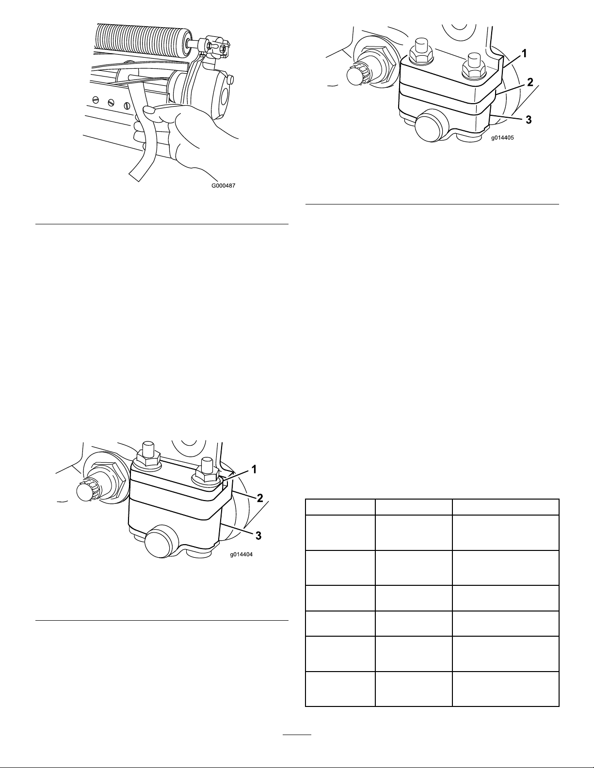
Note:Ensurethatthenutsonthebackofthe
bedbaradjustingboltsarenotrestingonthe
worksurface(Figure17).
3.Rotatethereelsothat1ofthebladescrosses
thebedknifeedgebetweentherstandsecond
bedknifeboltheadslocatedontherightsideof
thecuttingunit.
4.Makeanidentifyingmarkonthebladewhereit
crossesthebedknifeedge.
Note:Thismakeslateradjustmentseasier.
5.Inserta0.05mm(0.002inch)shim(T oroPart
No.140-5531)betweenthebladeandthe
bedknifeedgeatthepointmarkedinstep4.
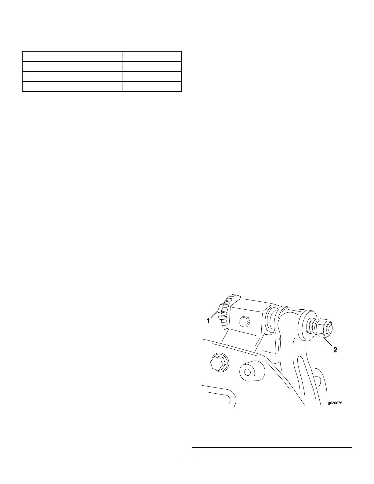
6.Turntherightbedbaradjustingbolt(Figure9)
untilyoufeellightpressureontheshimwhen
slidingitside-to-side.Removetheshim.
7.Fortheleftsideofthecuttingunit,slowlyrotate
thereelsothattheclosestbladecrossesthe
bedknifeedgebetweentherstandsecondbolt
heads.
8.Repeatsteps4through6fortheleftsideofthe
cuttingunitandleftbedbaradjustingbolt.
9.Repeatsteps5and6untilthereislightpressure
atthecontactpointsonboththeleftandright
sidesofthecuttingunit.
10.Toobtainlightcontactbetweenthereeland
bedknife,turneachbedbaradjustingbolt
clockwise3clicks.
Note:Eachclickonthebedbaradjustingbolt
movesthebedknife0.018mm(0.0007inches).
Donotovertightentheadjustingbolts.
Turningtheadjustingboltclockwisemoves
thebedknifeedgeclosertothereel.Turning
theadjustingboltcounterclockwisemovesthe
bedknifeedgeawayfromthereel.
11.Insertalongstripofcuttingperformancepaper
(ToroPartNo.125-5610)betweenthereeland
bedknife,perpendiculartothebedknife(Figure
10),thenslowlyrotatethereelforward;itshould
cutthepaper;ifnot,turneachbedbaradjusting
boltclockwise1clicksandrepeatthisstepuntil
itcutsthepaper.
9

g000487
Figure10
Note:Ifexcessivecontact/reeldragisevident,
backlap,refacethefrontofthebedknife,orgrind
thecuttingunittoachievethesharpedgesneeded
forprecisioncutting(RefertotheToroManualfor
SharpeningReelandRotaryMowers,FormNo.
09168SL).
AdjustingtheRear-RollerHeight
Dependingonyourdesiredheight-of-cutrange,you
needtoadjusttherear-rollerbrackets(Figure11or
Figure12)totheloworhighposition:
•Positionthespacerabovethesideplate-mounting
ange(factorysetting)whentheheight-of-cut
settingsrangefrom1.5mmto6mm(1/16inchto
1/4inch)asshowninFigure11.
g014404
Figure11
1.Spacer3.Rollerbracket
2.Sideplate-mountingange
•Positionthespacerbelowthesideplate-mounting
angewhentheheight-of-cutsettingsrangefrom
3mmto25mm(1/8inchto1inch)asshownin
Figure12.
g014405
Figure12
1.Sideplate-mountingange3.Rollerbracket
2.Spacer
1.Raisetherearofthecuttingunitandplacea
blockunderthebedknife.
2.Removethe2nutssecuringeachrollerbracket
andspacertoeachsideplatemountingange.
3.Lowertherollerandboltsfromthesideplate
mountingangesandspacers.
4.Placethespacersontotheboltsaboveorbelow
therollerbrackets,asrequired(Figure11or
Figure12).
5.Securetherollerbracketandspacerstothe
undersideofthemountingangeswiththenuts
previouslyremoved.
Note:Thepositionoftherearrollertothereel
iscontrolledbythemachiningtolerancesofthe
assembledcomponentsandparallelingisnot
required.
AdjustingtheHeightofCut
Usethefollowingcharttodeterminewhichbedknifeis
bestsuitedforthedesiredheightofcut.
BedknifePartNo.Height-of-Cut
Edgemax
Micro-cut
(Standard)
115-18801.5to4.7mm(0.062to
0.188inch)
Edgemax
Tournament
(Optional)
115-18813.1to12.7mm(0.125to
0.500inch)
Micro-cut
(Optional)
93-42621.5to4.7mm(0.062to
0.188inch)
Tournament
(Optional)
93-42633.1to12.7mm(0.125to
0.500inch)
Extended
Micro-cut
(Optional)
108-43031.5to4.7mm(0.062to
0.188inch)
Extended
Tournament
(Optional)
108-43023.1to12.7mm(0.125to
0.500inch)
10

Low-cut
(Optional)
93-42644.7to25.4mm(0.188to
1.00inch)
High-cut
(Optional)
94-63927.9to25.4mm(0.312to
1.00inch)
Fairway
(Optional)
137–60979.5to25.4mm(0.375to
1.00inch)
Fairway
EdgeMax
(optional)
137-60929.5to25.4mm(0.375to
1.00inch)
Note:Forheightsofcutgreaterthan9.5mm(0.375
inch),installthehigh-height-of-cutkit.
AdjustingtheHeight-of-CutGauge
Beforeadjustingtheheightofcut,settheheight-of-cut
gaugeasfollows:
1.Loosenthenutonthegaugebarandsetthe
adjustingbolttothedesiredheightofcut(Figure
13).
Note:Thedistancebetweenthebottomofthe
boltheadandthefaceofbaristheheightofcut.
g000489
Figure13
1.Gaugebar3.Nut
2.Height-adjustingbolt
2.Tightenthenut.
AdjustingtheHeightofCut
1.Loosenthelocknutssecuringtheheight-of-cut
armstothecutting-unitsideplates(Figure14).
g278482
Figure14
1.Height-of-cutarm3.Adjustingbolt
2.Locknut
2.Hooktheboltheadoftheheight-of-cutgauge
ontotherightsideofthecuttingedgeofthe
bedknifeandresttherearendofthebaronto
therearoftheroller(Figure15).
g004003
Figure15
1.Gaugebar
3.Rotatetheadjustingboltuntiltherollercontacts
thefrontofthegaugebar.
4.Repeatsteps2and3fortheleftside.
5.Adjustbothendsoftherolleruntiltheentire
rollerisparalleltothebedknife.
Important:Whensetproperly,therear
andfrontrollerscontactthegaugebarand
theboltissnugagainstthebedknife.This
ensuresthattheheightofcutisidenticalat
bothendsofthebedknife.
6.Tightenthenutstosecuretheadjustment
enoughtoremoveplayfromthewasher.
11

7.Verifythattheheight-of-cutsettingiscorrect;
repeatthisprocedureifnecessary.
AdjustingtheCut-OffBar
Adjustthecut-offbartoensurethattheclippingsare
cleanlydischargedfromthereelarea,asfollows:
Note:Thebarisadjustabletocompensatefor
changesinturfconditions.Adjustthebarcloserto
thereelwhentheturfisextremelydry.Bycontrast,
adjustthebarfurtherawayfromthereelwhenthe
turfconditionsarewet.Thebarshouldbeparallelto
thereeltoensureoptimumperformance.Adjustit
wheneveryousharpenthereel.
1.Loosentheboltssecuringthetopbar(Figure
16)tothecuttingunit.
g014643
Figure16
1.Cut-offbar
2.Inserta1.5mm(0.060inch)feelergauge
betweenthetopofthereelandthebarthen
tightenthebolts.
Important:Ensurethatthebarandreelare
equaldistanceapartacrossthecomplete
reel.
Note:Adjustthegapasneededforyourturf
conditions.
12

Maintenance
Note:Determinetheleftandrightsidesofthe
machinefromthenormaloperatingposition.
SupportingtheCuttingUnit
Wheneveryouneedtotipthecuttingunittoexpose
thebedknife/reel,propuptherearofthecutting
unittoensurethatthenutsonthebackendofthe
bedbar-adjustingboltsarenotrestingonthework
surface(Figure17).
g016511
Figure17
1.Prop(notprovided)2.Bedbar-adjusting-screw
nut(2)
Relief-GrindingtheReel
Thenewreelhasalandwidthof0.76to1.27mm
(0.030to0.050inch)anda30°reliefgrind.
Whenthelandwidthgetslargerthan3mm(0.120
inch)wide,dothefollowing:
1.Applya30°reliefgrindonallreelbladesuntil
thelandwidthis0.76to1.27mm(0.030to0.050
inch)wide(Figure18).
g278332
Figure18
1.30°2.1.3mm(0.050inch)
2.Spingrindthereeltoachieve<0.025mm(0.001
inch)reelrun-out.
Note:Thiscausesthelandwidthtogrow
slightly.
Note:T oextendthelongevityofthesharpnessofthe
edgeofthereelandthebedknife—aftergrindingthe
reeland/orthebedknife—checkthereeltobedknife
contactagainaftercutting6greens,asanyburrs
willberemoved,whichmaycreateimproperreelto
bedknifeclearanceandthusacceleratewear.
ServicingtheBedbar
Onlyaproperlytrainedmechanicshouldservice
thebedbarandbedknifetopreventdamagetothe
reel,bedbar,orbedknife.Ideally,takethecutting
unittoyourauthorizedthemanufacturerdistributor
forservice.RefertotheServiceManualforyour
tractionunitforcompleteinstructions,specialtools,
anddiagramsforservicingthebedknife.Should
youeverneedtoremoveorassemblethebedbar
yourself,instructionsareprovidedbelow,asarethe
specicationsforservicingthebedknife.
Important:Alwaysfollowthebedknife
proceduresdetailedinyourServiceManualwhen
servicingthebedknife.Failuretoinstallandgrind
thebedknifecorrectlycanleadtodamagetothe
reel,bedbar,orbedknife.
13

RemovingtheBedbar
1.Turnthebedbaradjustingscrew,
counterclockwise,tobackthebedknife
awayfromthereel(Figure19).
g016429
Figure19
1.Bedbar-adjustingscrew3.Bedbar
2.Spring-tensionnut4.Washer
2.Backoutthespring-tensionnutuntilthewasher
isnolongertensionedagainstthebedbar
(Figure19).
3.Oneachsideofthemachine,loosenthelocknut
securingthebedbarbolt(Figure20).
g014409
Figure20
1.Bedbarbolt2.Locknut
4.Removeeachbedbarboltallowingthebedbar
tobepulleddownwardandremovedfromthe
cuttingunit(Figure20).
Accountforthe2nylonwashersand1steel
washeroneachendofthebedbar(Figure21).
g020056
Figure21
1.Bedbarbolt3.Nylonwasher
2.Nut4.Steelwasher
AssemblingtheBedbar
1.Installthebedbar,positioningthemountingears
betweenthewashersandthebedbar-adjusting
screw(Figure19).
2.Securethebedbartoeachsideplatewiththe
bedbarbolts(nutsonbolts)and3washers(6
total).
3.Positionanylonwasheroneachsideofthe
side-plateboss.Placeasteelwasheroutside
eachofthenylonwashers(Figure21).
4.T orquethebedbarboltsto27to36N∙m(240to
320inch-lb).
5.Tightenthelocknutsuntilyouremovetheend
playfromsteelwashers,butyouareableto
rotatethembyhand.Thewashersontheinside
mayhaveagap.
Important:Donotovertightenthelocknuts
ortheywilldeectthesideplates.
6.Tightenthespringtensionnutuntilthespringis
collapsed,thenbackitoff1/2turn(Figure22).
14

g016470
Figure22
1.Spring-tensionnut2.Spring
7.Adjustthebedknifetothereel;refertoAdjusting
theBedknifetotheReel(page9).
CheckingtheTopGrind
Angle
Theanglethatyouusetogrindyourbedknivesis
veryimportant.
Usetheangleindicatorandtheangle-indicatormount
tochecktheanglethatyourgrinderproducesand
thencorrectforanygrinderinaccuracy.
1.Placetheangleindicatoronthebottomsideof
thebedknifeasshowninFigure23.
g034113
Figure23
1.Bedknife(vertical)2.Angleindicator
2.PresstheAltZerobuttonontheangleindicator.
3.Placetheangle-indicatormountontheedge
ofthebedknifesothattheedgeofthemagnet
mateswiththeedgeofthebedknife(Figure24).
Note:Thedigitaldisplayshouldbevisiblefrom
thesamesideduringthisstepasitwasinstep1.
g034114
Figure24
1.Angle-indicatormount3.Bedknife
2.Edgeofthemagnetmated
withtheedgeofthe
bedknife
4.Angleindicator
4.Placetheangleindicatoronthemountasshown
inFigure24.
Note:Thisistheanglethatyourgrinder
produces,andshouldbewithin2°ofthe
recommendedtopgrindangle.
ReelGrinding
Specications
ReelDiameter(New)128.5mm(5.06inches)
ServiceLimit-ReelDiameter114.3mm(4.50inches)
ReelShaftDiameter(OD)34.9mm(1.375inches)
BladeReliefAngle30°
BladeReliefAngleRange28–32°
BladeLandWidth1mm(0.040inch)
BladeLandWidthRange0.8to1.2mm(0.030to0.050
inch)
ServiceLimit-ReelDiameter
Taper
0.25mm(0.010inch)
15

InstallingtheBedknife
1.Removetherust,scale,andcorrosionfromthe
bedbarsurfaceandapplyathinlayerofoilto
thebedbarsurface.
2.Cleanthescrewthreads.
3.Applynever-seizecompoundtothescrewsand
installthebedknifetothebedbar.
g255045
Figure25
1.Bedbar3.Screw
2.Bedknife
4.T orquethe2outerscrewsto1N∙m(10in-lb).
5.Workingformthecenterofthebedknife,torque
thescrewsto23to28N∙m(200to250in-lb).
g255046
Figure26
1.Bednifescrewtool3.Torqueto23to28N∙m
(200to250in-lb).
2.Installandtorquethese
rstto1N∙m(10in-lb).
6.Grindthebedknife.
16

BacklappingtheCutting
Unit
DANGER
Contactwiththereelorothermovingparts
canresultinpersonalinjury.
Keepyourngers,hands,andclothingaway
fromthereelsorothermovingparts.
•Stayawayfromthereelwhilebacklapping.
•Neveruseashorthandledpaintbrush
forbacklapping.PartNo.29-9100Handle
assemblycompleteorindividualpartsare
availablefromyourlocalauthorizedToro
distributor.
1.Positionthemachineonaclean,levelsurface,
lowerthecuttingunits,stoptheengine,engage
theparkingbrake,andremovetheignitionkey.
2.Removethereelmotorsfromthecuttingunits
anddisconnectandremovethecuttingunits
fromtheliftarms.
3.Connectthebacklappingmachinetothecutting
unitbyinsertingapieceof3/8inchsquarestock
intothesplinedcouplingintheendofthecutting
unit.
Note:Additionalinstructionsandprocedures
onBacklappingareavailableinyourtraction
unitOperator’sManualandtheToroSharpening
ReelandRotaryMowersManual,FormNumber
80-300PT.
Note:Forabettercuttingedge,runale
acrossthefrontfaceofthebedknifeandreel
whenthelappingoperationiscompleted.This
willremoveanyburrsorroughedgesthatmay
havebuiltuponthecuttingedge.
17

ServicingtheRoller
TheGreensRollerRebuildKit(PartNo.140-5552)andtheGreensRollerRebuildToolKit(PartNo.140-5553)
(Figure27)areavailableforservicingtheroller.TheRollerRebuildKitincludesallthebearings,bearing
nuts,andsealstorebuildaroller.
TheRollerRebuildToolKitincludesallthetoolsandtheinstallationinstructionsrequiredtorebuildarollerwith
therollerrebuildkit.RefertoyourpartscatalogorcontactyourauthorizedT orodistributorforassistance.
g346125
Figure27
1.GreensRollerRebuildKit(PartNo.140-5552)5.V-ring
2.GreensRollerRebuildToolkit(PartNo.140-5553)6.Bearinglocknut
3.Bearing7.Flatwasher
4.Seal8.Bearing/outer-sealtool
18

Notes:

DeclarationofIncorporation
TheT oroCompany,8111LyndaleAve.South,Bloomington,MN,USAdeclaresthatthefollowingunit(s)
conform(s)tothedirectiveslisted,wheninstalledinaccordancewiththeaccompanyinginstructionsontocertain
ToromodelsasindicatedontherelevantDeclarationsofConformity.
ModelNo.SerialNo.ProductDescriptionInvoiceDescriptionGeneralDescriptionDirective
04652408000000andUp8-BladeDPAReelMower8BLADECUTTINGUNIT
NGDPA8-BladeDPAReelMower2006/42/EC,
2000/14/EC
04654408000000andUp11-BladeDPAReelMower11BLADECUTTING
UNITNGDPA11-BladeDPAReelMower2006/42/EC,
2000/14/EC
04656408000000andUp14-BladeDPAReelMower14BLADECUTTING
UNITNGDPA14-BladeDPAReelMower2006/42/EC,
2000/14/EC
RelevanttechnicaldocumentationhasbeencompiledasrequiredperPartBofAnnexVIIof2006/42/EC.
Wewillundertaketotransmit,inresponsetorequestsbynationalauthorities,relevantinformationonthispartly
completedmachinery.Themethodoftransmissionshallbeelectronictransmittal.
ThismachineryshallnotbeputintoserviceuntilincorporatedintoapprovedToromodelsasindicatedonthe
associatedDeclarationofConformityandinaccordancewithallinstructions,wherebyitcanbedeclaredin
conformitywithallrelevantDirectives.
Certied:AuthorizedRepresentative:
MarcelDutrieux
ManagerEuropeanProductIntegrity
ToroEuropeNV
Nijverheidsstraat5
2260Oevel
Belgium
TomLangworthy
EngineeringDirector
8111LyndaleAve.South
Bloomington,MN55420,USA
October11,2022
This manual suits for next models
4
Table of contents
Other Toro Tractor Accessories manuals

Toro
Toro 136-8545 User manual

Toro
Toro 04651 User manual

Toro
Toro Wheel Horse XT Series User manual

Toro
Toro 03667 User manual

Toro
Toro 136-6311 User manual

Toro
Toro 79181 User manual

Toro
Toro Direct Drive Power Box Rake User manual

Toro
Toro 08733 User manual

Toro
Toro 08865 User manual

Toro
Toro Greensmaster TriFlex 3300 Series User manual