Baumuller BUM 62 User manual

E5.94005.12
Manual
Mono Power Unit
BUM 62, 63, 64

Titel Manual
Produkt Mono Power Unit
BUM 62, 63, 64
Version 5.94005.12
Stand 2001-01-04
Copyright These operating instructions may be copied by the owner
in any quantity but only for internal use. For other purposes
these operating instructions and extracts thereof must not
be copied or reproduced.
Use and disclosure of information contained in these oper-
ating instructions are not permitted.
Designations and company marks contained in these op-
erating instructions may be brand names, the use of which
by third parties for their own purposes may violate the
rights of the holders.
Obligatory These operating instructions are part of the equipment/ma-
chine. These operating instructions must be available to
the operator at all times and must be in a legible condition.
If the equipment/machine is sold or moved to a different lo-
cation these operating instructions must be passed on by
the owner together with the equipment/machine.
After any sale of the equipment/machine this original and
all copies must be handed over to the buyer. After disposal
or any other end of use this original and all copies must be
destroyed.
When the present operating instructions are handed over,
corresponding sets of operating instructions of a previous
version are automatically invalidated. Please notice that
specifications/data/information are current values ac-
cording to the printing date. These statements are not
legally binding according to the measurement, computa-
tion and calculations.
Baumüller Nürnberg GmbH reserves the right, in develop-
ing its products further, to change the technical specifica-
tions and the handling of the products concerned without
prior notice.
No liability can be accepted concerning the correctness of
the operating instructions unless otherwise specified in the
General Conditions of Sale and Delivery.
Manufacturer Baumüller Nürnberg GmbH
Ostendstr. 80 - 90
D-90482 Nürnberg
Germany
Tel. +49 9 11 54 32 - 0 Fax: +49 9 11 54 32 - 1 30
www.baumueller.de

Mono Power Unit BUM 62, 63, 64 3
Baumüller Nürnberg GmbH 5.94005.12
Table of Contents
TABLE OF CONTENTS
1 Safety Notes ........................................................................................................ 5
2 Technical Data .................................................................................................... 9
2.1 General ................................................................................................................................... 9
2.2 Electrical data ....................................................................................................................... 12
2.3 Type code ............................................................................................................................. 14
3 Transportation, Unpacking .............................................................................. 15
4 Assembly ........................................................................................................... 17
4.1 Dimensions ........................................................................................................................... 18
4.2 Assembly information ........................................................................................................... 21
4.3 Fastening .............................................................................................................................. 22
5 Installation ......................................................................................................... 23
5.1 Danger information ............................................................................................................... 23
5.2 Standardization information .................................................................................................. 24
5.3 EMC information ................................................................................................................... 26
5.4 Safety relay ........................................................................................................................... 33
5.5 Terminal diagrams ................................................................................................................ 39
5.6 Connector pin assignment .................................................................................................... 44
5.7 Accessories .......................................................................................................................... 49
6 Commissioning ................................................................................................. 51
6.1 Danger information ............................................................................................................... 51
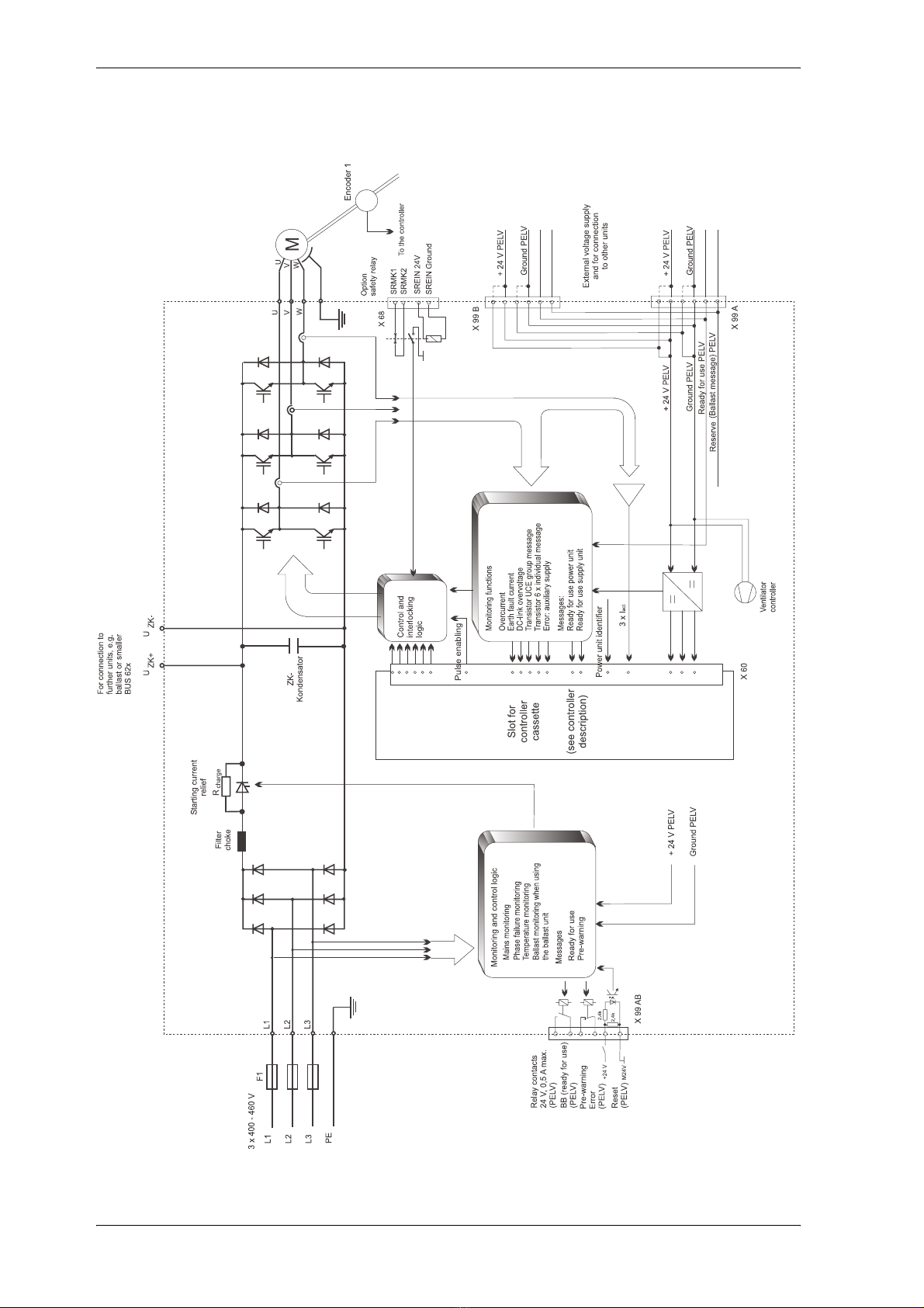
6.2 Function diagram BUM 62 .................................................................................................... 53
6.3 Function diagram BUM 63/64 ............................................................................................... 54
6.4 Operation .............................................................................................................................. 55
6.5 Messages and warnings ....................................................................................................... 56
6.6 Monitoring motor-end power unit .......................................................................................... 58
6.7 Voltage failure ....................................................................................................................... 61
7 Maintenance ...................................................................................................... 63
7.1 Maintenance notes ............................................................................................................... 63
7.2 Environmental conditions ..................................................................................................... 64
7.3 Recommissioning ................................................................................................................. 64
7.4 Disposal ................................................................................................................................ 65
8 Appendix ........................................................................................................... 67
8.1 Manufacturer Declaration ..................................................................................................... 67
8.2 Declaration of Conformity ..................................................................................................... 68
8.3 General Conditions of Sale and Delivery .............................................................................. 69
8.4 Index ..................................................................................................................................... 72

Abbreviations
4Mono Power Unit BUM 62, 63, 64
5.94005.12 Baumüller Nürnberg GmbH
ABBREVIATIONS
AC Alternating current
AM Asynchronous motor
a.m.s.l. above mean sea level
BUC Baumüller Feed/Feed back Unit
BUG Baumüller Basic Feed Unit
BUM Baumüller Mono Power Unit
BUS Baumüller Power Module
DC Direct current
DIN Deutsches Institut für Normung e.V.
(German Standardization Authority)
EMC Electromagnetic compatibility
EN European standard
HS Main contactor
PELV Protective extra-low voltage
SELV Safe extra-low voltage
MSL Main Sea Level
SL Protective earth
SM Synchronous motor
ZK DC link

Safety Notes
Mono Power Unit BUM 62, 63, 64 5
Baumüller Nürnberg GmbH 5.94005.12
1 SAFETY NOTES
Introductory remarks
During operation, the principles on which the converter and motor work, lead to leakage currents to earth
which are dissipated via specified protective earth connections and which may result in a current-oper-
ated e.l.c.b. on the input side blowing prematurely.
A DC component in the fault current may occur in the event of a short-circuit to frame or earth fault which
makes a triggering of the higher-level current-operated e.l.c.b. more difficult or even impossible.
The connection of the current controller to the mains using only the current-operated e.l.c.b. is prohibited
(preliminary standard EN 50178 / VDE 0160 /11.94, sections 5.2.11 and 5.3.2.1)
The units are protected against direct contact by being installed into common switching cabinets which
meet the minimum protection requirements according to pr EN 50178 / VDE 0160 / 11.94, section 5.2.4.
Sheets of plastic covering the control electronics, the power stage and the device connection, addition-
ally prevent accidental contact during commissioning and casual use of control elements located close
to the equipment.
(DIN VDE 0106 Part 100, Accident Prevention Regulation VBG4 ”Electrical Systems and Equipment).
The protective measures and safety regulations according to DIN/VDE are binding for personal security.
Neglecting to fit PE connections on the equipment or the motor will result in serious personal injury and/
or considerable damage to material assets.
It is only permitted to use the units on earth-protected supply mains.
The discharge time of live parts is > 1 min.
The units are partly short-circuit-proof.
General information
These operating instructions contain the information required for the application as directed of the prod-
ucts described herein. The document is intended for specially trained, skilled personnel who are well-
versed in all warnings and maintenance activities.
The units are manufactured using the state-of-the-art technology and are safe in operation. They can be
installed safely and commissioned and function without problems if the safety information below is ob-
served.
DANGER
When operating this electrical unit, some parts of the equipment always carry dangerous voltage.
Ignoring these safety instructions and warnings may result in death, serious personal injury and/or
damage to material assets.
Only qualified personnel who are familiar with the safety information, assembly, operation and
maintenance instructions may carry out work on this unit.

Safety Notes
6Mono Power Unit BUM 62, 63, 64
5.94005.12 Baumüller Nürnberg GmbH
Danger information
In the context of the operating instructions and the information on the products themselves, the terms
used have the following meanings:
Qualified personnel
In the sense of the safety-relevant information in this document or on the products themselves, qualified
personnel are considered to be persons who are familiar with setting up, assembling, commissioning and
operating the product and who have qualifications appropriate to their activities.
yTrained or instructed or authorized to commission, ground and mark circuits and equipment in
accordance with recognized safety standards.
yTrained or instructed in accordance with recognized safety standards in the care and use of
appropriate safety equipment.
One the one hand, the information below is for you own personal safety and on the other to prevent
damage to the described products or to other connected units.
DANGER
This means that death, severe personal injury or considerable damage to material assets
will occur, unless appropriate safety measures are taken.
WARNING
This means that death, severe personal injury or considerable damage to material assets
may occur, unless appropriate safety measures are taken.
NOTE
This draws your attention to important information about the product, handling of the product or to
a particular section of the documentation.

Safety Notes
Mono Power Unit BUM 62, 63, 64 7
Baumüller Nürnberg GmbH 5.94005.12
Application as directed
Voltage test
BAUMÜLLER carries out a voltage test according to prEN 50178 / VDE 0160 /11.94, Section 9.4.5 for
each unit.
Subsequent high-voltage tests must only be carried out by BAUMÜLLER NÜRNBERG GmbH.
WARNING
You may only use the unit/system for the purposes specified in the operating instructions and in
conjunction with the third-party equipment and components recommended or authorized by
BAUMÜLLER NÜRNBERG GmbH.
For safety reasons, you must not change or add components on/to the unit. The operator must report
immediately any changes that occur which adversely affect the safety of the unit/system.
WARNING
If you want to carry out high-voltage tests for complete switch cabinet installations, disconnect all
cables from BAUMÜLLER units prior to the test.

Safety Notes
8Mono Power Unit BUM 62, 63, 64
5.94005.12 Baumüller Nürnberg GmbH

Technical Data
Mono Power Unit BUM 62, 63, 64 9
Baumüller Nürnberg GmbH 5.94005.12
2 TECHNICAL DATA
2.1 General
The mono power units BUM 62, BUM 63 and BUM 64 complete the upper power range of the Baumüller
Modular System.
They are produced as compact converter units and contain the mains supply as well as the motor-end
power unit.
The rack-mounted modules of the Baumüller Modular System are designed for control tasks. As a result,
the drives can be adapted to a wide variety of requirements.
There are two types of controller.
The BUS 6 E controller for almost all applications in constructional engineering.
The BUS 6 T controller for highly demanding control tasks.
As both controllers are equipped to be rack-mounted, separate descriptions are available with the re-
spective characteristics and technical data.
Depending on the application, the unit can be delivered in variations from simple frequency converters
to highly dynamic and precise vector controllers.
With the BUM 62, BUM 63 and BUM 64 mono power units, both asynchronous and synchronous mo-
tors with different encoder systems can be driven by the same unit.
2.1.1 Function description
The BUM 62, 63 and 64 units consist of two parts, the supply converter and the motor-end inverter.
yBUM 62:
The supply converter for creation of the intermediate circuit voltage is an uncontrolled diode bridge.
The intermediate circuit capacitors are charged via a charging resistance to reduce peak starting cur-
rent, which is bridged by a thyristor after switching on.
yBUM 63 and 64:
The supply converter is a thyristor bridge. The starting current is limited, on switching on, by con-
trolling the thyristor converter current .
yBUM 62, 63 and 64:
The IGBT motor-side inverter processes the transistor control signals sent by one of the controllers
plugged into the slot, and makes the control measurement signals available. The mono unit has
monitoring facilities of its own (self-protecting power unit).

Technical Data
10 Mono Power Unit BUM 62, 63, 64
5.94005.12 Baumüller Nürnberg GmbH
2.1.2 Block diagram BUM 62

Technical Data
Mono Power Unit BUM 62, 63, 64 11
Baumüller Nürnberg GmbH 5.94005.12
2.1.3 Block diagram BUM 63/64

Technical Data
12 Mono Power Unit BUM 62, 63, 64
5.94005.12 Baumüller Nürnberg GmbH
2.2 Electrical data
* not supplied, must be ordered extra
1) connection voltage equal 400 VAC
2) clock frequency equal 4 kHz
3) t < 2 min (when cooling element temperature = ambient temperature)
4) Installation height > 1000 m see characteristic curve 1
BUM 62 BUM 63 BUM 64
Control * slot for BUS 6 controller cassette
Connection voltage 3 x 400 VAC ±10 %, 50 Hz
3 x 460 VAC +10 % -25 %, 60 Hz
Semi-conductor fuses (external) 100 A 250 A 350 A
Nominal DC-link voltage 1) 540 V DC
Total connectable capacitors in the DC-link
(encl.. supply unit) 2200 µFunlimited,
pay attention to extended charge time
Internal DC-link capacitors 1000 µF2460 µF4100 µF
Switch on: ready for use after ≤1,5 s ≤1,5 s without additional DC-link capacitors
Choke external no 4 % uk4 % uk
Output voltage (AC) 0 ... supply voltage
Output power 1) 2) 52 kVA 104 kVA 208 kVA
Typical motor power 1) 2) 35 kW 70 kW 140 kW
Nominal output current (Ieff) 1) 2)
at TK = 45 °C and TB= 45 °C 75 A 150 A 300 A
Peak output current (Ieff) 2) 3)
at TK = 45 °C and TB= 45 °C 97,5 A 195 A 390 A
Connecting voltage fan 5) - - 3x400 VAC ±10 %
50/60 Hz
Control voltage 6) + 24 VDC ±20 %
Power consumption control voltage without
controller 65 W 80 W 50 W
Power loss in nominal use 1) 2) 1410 W 2450 W 4900 W
Operation ambient temperature range TB0 ... 45 °C (with power reduction 55 °C)
Coolant medium temperature range TK0 ... 45 °C (with power reduction 55 °C)
Reduction output current
TK= 45 ... 55 °C 3 % / °C
Installation height 4) 1000 m above sea level
Relative air humidity 15 % ... 85 % no dew
Storage temperature range - 30 °C ... + 70 °C
Dimensions (B x H x T) 328 x 460 x 280 mm 490 x 562 x 282 mm 490 x 990 x 282 mm
Weight without controller 35 kg 60 kg 95 kg

Technical Data
Mono Power Unit BUM 62, 63, 64 13
Baumüller Nürnberg GmbH 5.94005.12
5) The output power must be reduced if the fan’s connection voltage < 400 V. The fan cannot be supplied directly by mains volt-
age if the mains voltage > 440 V. Ensure the necessary supply voltage e.g. by an transformer (power: 110 VA/50Hz or 160
VA/60 Hz)
6) with reference to EN61131-2 (table 5)
Only BUM 62 and BUM 63: The internal fan power is reduced if control voltage < 24 V. You must reduce the output currents
when the control voltage < 24 V.
Characteristic curve 1: Load in dependence on installation height
Characteristic curve 2: Current reduction dependent on mains voltage

Technical Data
14 Mono Power Unit BUM 62, 63, 64
5.94005.12 Baumüller Nürnberg GmbH
2.3 Type code

Transportation, Unpacking
Mono Power Unit BUM 62, 63, 64 15
Baumüller Nürnberg GmbH 5.94005.12
3 TRANSPORTATION, UNPACKING
The units are packed at the factory in accordance with the order.
You should avoid jarring packages in transit or jolting them, e.g. when setting them down on the ground.
After unpacking the package(s) and checking that the shipment is complete, you can start assembly.
Fibre board, cartridge paper and/or wood are used as packaging materials and they can be disposed of
in accordance with local regulations.
Report any damage in transit without delay.
DANGER
If the unit has been damaged in transit, do not connect it to the mains until appropriate high-voltage
testing has been carried out.
Ignoring this information can result in death, severe personal injury, or considerable damage to prop-
erty

Transportation, Unpacking
16 Mono Power Unit BUM 62, 63, 64
5.94005.12 Baumüller Nürnberg GmbH

Assembly
Mono Power Unit BUM 62, 63, 64 17
Baumüller Nürnberg GmbH 5.94005.12
4 ASSEMBLY
WARNING
The user is responsible for the assembly of the converter power unit, the motor and the other compo-
nents according to applicable safety standards (e.g. DIN, VDE) and all other relevant national or local
regulations regarding conductor dimensions and fusing, grounding, circuit breakers, overcurrent pro-
tection etc.
A space must be left above and below the units, and sufficient cool air and air circulation must be pro-
vided.
Sheets of plastic on the devices that cover the equipment connection act as additional guards pre-
venting accidental contact at commissioning and in the case of casual use of control elements located
close to the equipment (DIN VDE 0106 Part 100, Accident Prevention Regulation VBG4 "Electrical
Systems and Equipment").
Pollution degree 3 and 4 according to EN 50178/VDE0160/4.98 Section. 5.2.15.2 must be avoided.
The units are suitable for the installation in closed operating rooms. (VDE 0558 Part 1a, Section
5.4.3.2.1 and 5.4.3.2.2

Assembly
18 Mono Power Unit BUM 62, 63, 64
5.94005.12 Baumüller Nürnberg GmbH
4.1 Dimensions
4.1.1 Dimensions BUM 62
For the total depth pay attention to the controller’s size!

Assembly
Mono Power Unit BUM 62, 63, 64 19
Baumüller Nürnberg GmbH 5.94005.12
4.1.2 Dimensions BUM 63
For the total depth pay attention to the controller’s size!

Assembly
20 Mono Power Unit BUM 62, 63, 64
5.94005.12 Baumüller Nürnberg GmbH
4.1.3 Dimensions BUM 64
Für die Gesamttiefe ist die Reglergröße zu beachten!
This manual suits for next models
2
Table of contents
Other Baumuller Portable Generator manuals