bautek Fluggeräte Kite User manual

Operating instructions / April 2009
bautek Fluggeräte GmbH
Gewerbegebiet, 54344 Kenn, Deutschland

-1-
Operating instructions Kite (As of April 2009)
General
With the Kite you have purchased a very powerful kingposted device of the newest
generation with integrated swivel tips. The perfect sail position, the low weight and the
balanced flight characteristics of the Kite will make you delight. The structural elasticity
of the device was designed so that even with fully strained VG good controllability is
maintained. That mediates in the fast gliding in the crowd, or close to the slope a secure
feeling. At the start a spring system integrated in the cross tube clamps the lower
sidewires and thus facilitates the alignment of the device before starting.
The classic structure of the Kite with aluminum tubes and steel cable suspensions has
proven itself for decades in hanggliding. Everything opens up to check any damage
well and easily, and the first official check is only due after 60 months.
Thanks to many clever construction details the set up and break down of this glider is
exemplary simple, and without effort.
Before the first time set-up, it is necessary to read this manual thoroughly.
The enclosed “Air sport equipment certificate” is part of this manual.
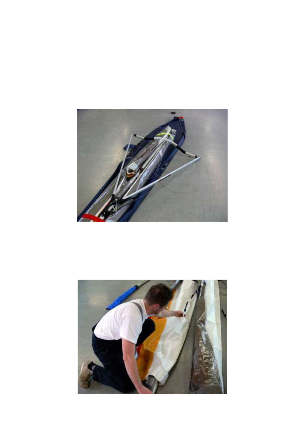
Assembly from the short pack of 3.8 m. (Combi cover bag long / short required,
Standard = Long cover bag)
-2-
Lay down the short pack with the control bar area pointing up. Open the zipper and put
the batten bundle [quiver] and both rear leading edge [wing tubes] to the side. If you
are flying with non-split wheels, slide these on the speed bar now, before mounting it.
The bow of the speed bar is pointing up, when assembling. Alternatively the use of a
profiled bautek- Alu-speedbar [with or without wheels] is an option. Attach the speed
bar right and left with the push-pins at the control bar corners.
Now turn the wing over so it lies on the control bar and open the Velcro ties.
Unfold the rear sail-halves to the rear and the swivel-tip of the right and left outside [=
rear] leading edge tube towards the front in the direction of the keel.

-3-
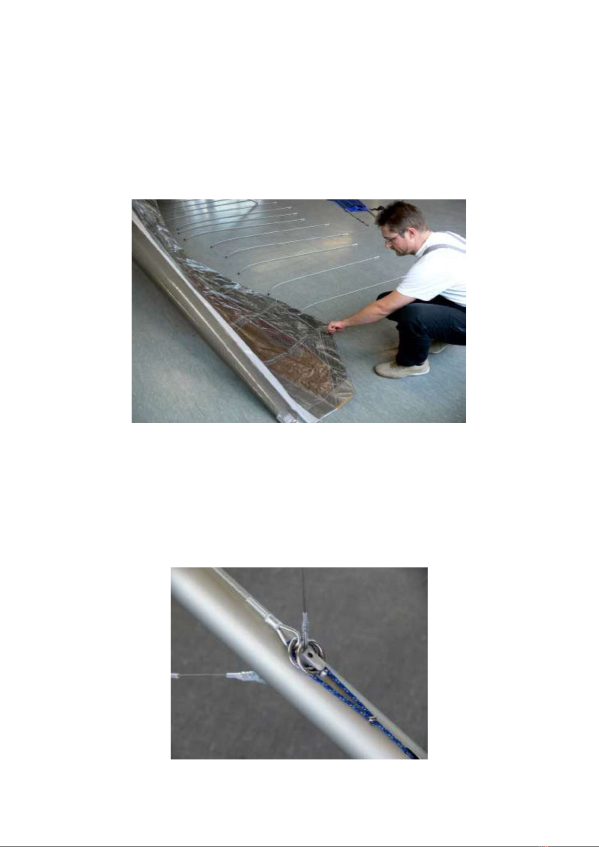
Push the rear sections of the leading edge tubes from the rear into the sail. Let the
swivel tip exit the double sail at the zipper opening and push the tube into the front
leading edge tube with the swivel tip cable pointing up. The swivel tip will swing to the
rear. Press both snaps in and see that both snap out again through the holes in the
front tube.
Then pull the wide, black, inside loop at the end of the sail leading edge over the end-
cap of the rear leading-edge tube. There is an auxiliary loop, which helps to do this.
Pay attention to the proper seating of the loop webbing in the grove of the plastic end-
cap. Close the Velcro loop inside the sail to keep the black loop from moving out of its
grove during transport.
Spreading the sail and inserting the upper battens
Stand the glider on the control bar and raise the kingpost.
-4-
Spread the wings in steps, since the spreader bar has limited float.
In strong winds keep the glider flat on the ground for the next steps.
Push the top battens 1-10, starting at the center with Batten 1, into their sail pockets
and secure them with the spring-loaded end plug, by pushing the plug forward against
the spring and releasing the flat tang into the open space in the trailing edge seam of
the sail.
Red batten numbers = left side, green batten numbers = right side, looking in flight
direction. [Portside and Starboard for the mariners] The batten quiver has separate
pockets for the right and left wing. After the top battens are inserted, you can stand the
glider up, if not done earlier, and tension it.
Before tensioning the glider, standing on the control bar, the wings should be spread
as far as possible. Out of the keel-pocket leads a tensioning line to an elongated hole
in the keel tube. Pull the spreader bar with this line to the rear and hang the steel ring
in the notch of the tension line receptacle.

-5-
Then the steel ring of the rear upper rigging placed in the same notch. Check if the
snap behind both rings is out and secures them.
In the front the two nose wires of the lower rigging are combined with a small screw
closed triangle. Hang the triangle into the receptacle under the nose plate and again
confirm that the snap secures it.
After this attach the snap hook of the spreader-bar safety cable from below = upwards
into the tensioning line eye at the spreader bar; the zipper of the double sail is closed
after this.
-6-
Folding tip battens tensioning
The folding mechanism of the tip battens allows their tensioning with ease.
Tension the tip batten always after the spreader bar is tensioned. With
detensioned mainframe [=spreader bar] the tip battens carry substantial higher loads!
For tensioning unfold the short end of the batten tube in the direction of the end of the
keel and insert its end plug into the web loop at the rear sail corner. Now with the open
hand [Warning: danger of pinching] inside the double sail and the other hand at the
sail corner, push the hinge of the batten past its balance point in the direction of the
end of the keel.
The disassembly of the tip battens done in the reverse manner.
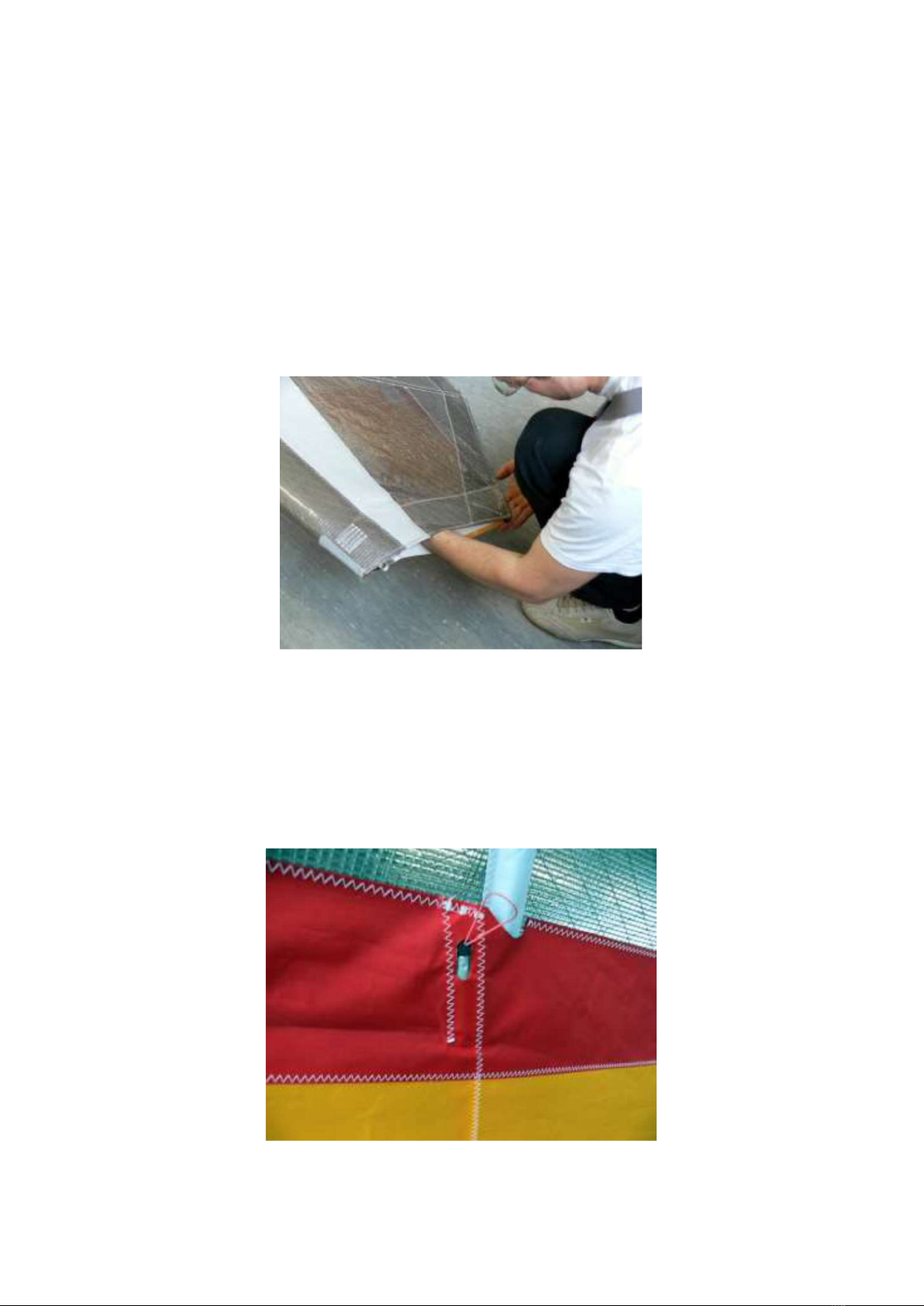
Inserting lower sail battens and folding out the Swivel-tips
Push the straight battens into their pockets in the lower sail; they are not specifically
marked, but clearly of different length; the elongated holes in the lower sail mark their
pockets. Insert them fully and secure them against the rear seam.
-7-
The swivel tips are now folded out and automatically secured in their rear pocket by
the closure of the zipper.
Caution!
Before relaxing the device, the tip battens must be relaxed, the zips open and
the swivel tips be folded!
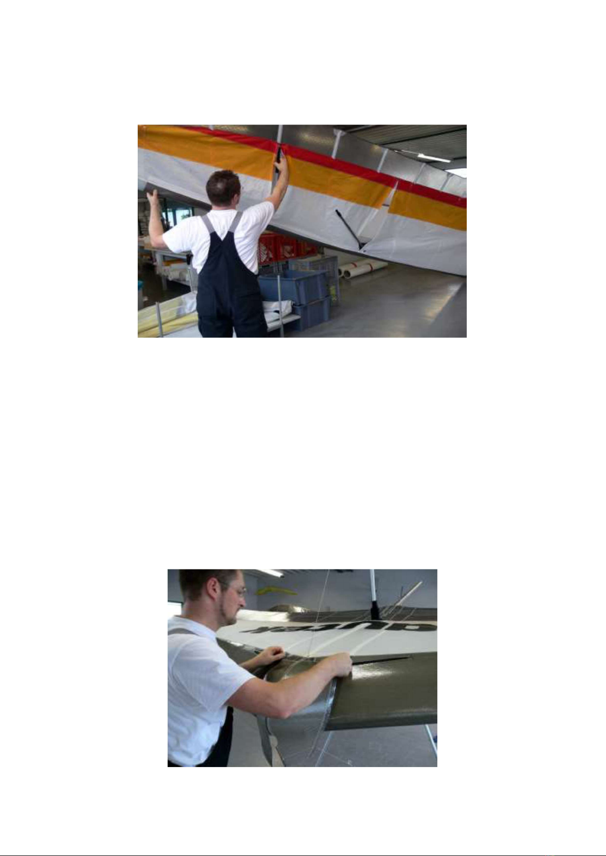
Attaching nose plate cover
The middle batten sits on the front nose plate screw and is secured by a rubber loop
in its position. In the leading edge right and left at the nose plate area are two short
zippers, which prevent folding of the leading edge in the cover / transport bag. Before
you place the nose plate cover as the last step of the set-up, take a look through the
opening of the upper sail at the nose plate area; make sure all parts are operational.
Close the two zippers in the leading edge and press the Velcro strips of the cover in
the proper position at the upper and lower sail on.

-8-
The glider is now flight-ready assembled.
Warning!
Open zips and / or unmounted nose plate cover results in a dangerous flight
behavior with negative control bar pressure. In this case fly as slow as possible
to the nearest landing site. Raindrops on the leading edge lead to a similar flight
behavior. In this case fly a little faster (drops will be partially blown away), no
tight turns and count on landing with an earlier and harder stall. Tip: rub the
leading edge with a dishwashing detergent before the start. That prevents the
drop formation and temporarily ensures almost normal flight characteristics
even in the rain.
Glider breakdown
The breakdown of the glider is done in reverse order of the assembly, with attention to
the following details:
Remove the nose cone and open both zippers at the leading edge, before you place
the glider down on the nose. Open the zippers of the four swivel tips and swing the
swivel tips outward. Pull the lower battens and detention the folding battens. Set the
glider on the end of the keel and detach the spreader bar safety cable and the triangle
of the nose wires. This triangle can be hooked into the snap hook of the spreader bar
safety cable, so it is close at hand at the next assembly. Pull the upper battens 10 – 1
right and left out of the sail and fold the wing in increments together. Roll up each side
of the sail and secure each side, separately at the middle swivel tip with a flour yellow
Velcro tie. The red tie is longer and is placed in front of the control frame apex. Each
rolled up sail end is put together with the folded swivel tip in the long cover bag.
Close the ties loosely to avoid permanent folds. Pull the cover bag over the standing
glider and close it’s zipper from the front up to the control frame apex. Now turn the
glider over, lay it on it’s back and remove the speed bar. Put the protective pouch,
sown to the cover bag, over both down tube ends. Lay the batten bag in the rear of the
cover bag. Close the zipper all the way.

-9-
Pre-flight check
Make it a habit, to do a careful pre-flight check before each start. Functioning
equipment and proper judgment of conditions and the weather reduce the risk
in hang gliding significantly.
1. Check from the nose plate the even bend of both leading edge tubes, the
symmetrical assembly of the glider and the “out” position of safety snap for the
nose wires.
2. Check for easy operation of the VG pulley system and proper functioning of the
VG jam cleat.
3. Base tube installed correctly and no cables kinked and tangs or eyes twisted?
4. Down tubes straight? Keel tube undamaged at control bar apex?
5. Check all lower rig cables, especially at eyes and press fittings.
6. Lift the glider at the rear end of the keel and check with tensioned VG for
symmetry of the glider, the swivel tips right and left and installation of the straight
battens and their secure seat in the double sail seam.
7. Tensioning line/cable ring seated correct in its seat?
8. Is the keel pocket screwed securely to the keel tube?
9. Are both pilot Hang strap and Safety strap correctly fastened and undamaged?
Periodically and after a crash inspect in addition:
All tubes for dents and bends as described in the maintenance and repair
protocol.
Upper and lower rigging right and left and the lines and cables inside the double
sail as well as the swivel tip cables.
Batten curves according to the batten chart.
Take-off
Always make a hang check before the start or always get in your harness after it is
hooked to the glider and the karabiner is locked. One standard routine needs to be
adopted. A hook-in check is essential immediately before any start.
The “Kite” is neutral on the shoulders and easy to guide on launch. The integral spring
system keeps the side wires tensioned, even when the VG is off; so there is no problem
to set proper attitudes and balance for the start. Start with a slow jog and accelerate
continuously till lift-off.
Close your harness after you are a safe distance from the ground and the glider
flies self-stabilizing.

-10-
Flight
The Kite has a variable geometry = nose angle [VG], with which the sail tension can
be increased in flight. With loose VG the wing has more twist, is neutral in turns and
easy to handle. For the first flight half tensioned VG is recommended to avoid over
controlling. Even with full tensioned VG the Kite can be controlled around the
vertical axis; in this configuration the wing has little twist and its best glide ratio. The
Kite is consistent in all speed ranges. The airflow separates late and can be controlled
well.
Landing
Landing starts at higher altitude with repeated checks of the wind direction. Only after
you are sure of the wind direction, should one decide on the approach and then stick
to it.
The Kite is easy to land. Fly the final approach in a straight glide with some extra speed
against the wind and let the glider lose its energy in ground effect. Change hand
position when the glider flies level and at trim speed. Keep your legs bent and
behind you till flare time; arch your back. Your upper body is thus closer to the
down tubes and you have a longer way for the flare. The Kite glides long in ground
effect and stalls soft and easy, with 1/3 VG harder but more definitive. If there is no
wind, you should use the control bar more energetically, at stronger wind only slightly
to flare for stand up landing.
Towing
The Kite is licensed for winch- and UL- tow. Requirements for this per DHV are:
A certified hand glider tow winch
Tow training of the pilot
Training of the winch operator and the UL-Pilot
A certified tow hook up / latch system
For the UL-tow the VG should be ca. 70-100 % tensioned. Then the glider has less
control bar pressure, but is still very controllable. Give at disturbances only short,
strong steering impulses with the hip [body center of gravity] and keep the tow
latch in the middle of the base tube. Do not support yourself on the base tube. Tip:
Pull in on the base tube with open hands.

-11-
General information and limitations
In Germany the Kite is type tested by the DHV and certified as a class 2 model.
The Kite is licensed to be flown only:
by pilots with a correspondent license and training
solo
with an angle of +30deg to -30deg to the horizon
with a roll angle up to 60deg, and
with a top speed of max. 90 km/h
The Kite is not to be used for aerobatics. It can be motorized with different motor
systems [take notice of the license].
The Kite got the certification of DHV airworthiness standards tested for hang
gliders valid in September 2006. This represents the current state of the art. This
level of knowledge is growing, and it may well be that previously unknown
physical relationships have been ignored. We therefore recommend that you
always consider a margin of safety when choosing the weather conditions in
which you want to start, as well as during your flight maneuvers.
Maximum flight enjoyment through optimal trimming
The sails of modern High Performance [HP] gliders are more tensioned and therefore
more sensitive to their configuration = trim. Sail fabric and sailconstruction tolerances
are with special measuring devices taken into account and individually corrected for.
Despite these in depth measuring techniques it might be necessary after some time,
to correct the basic trim.
Test the glider always in light thermal conditions, because changes in flight
characteristics are easier detected in moving air. It is certainly not the case that more
tension also brings about better performance. The sail tension in the direction of the
wingspan can be changed with the position of the leading edge end pieces and the
folding batten length. The end pieces are in standard production screwed through the
middle hole to the tube end.
In case you make any changes, we recommend, marking first the old position,
so that in case the change is unsuccessful, the original position can be found
again.
Center of gravity
The Kite should fly ca. 30-35km/h with hands off = at trim. By repositioning the kingpost
in its base [2 allen key nuts] the center of gravity can be adjusted. Moving forward =
nose heavy = faster, to the rear = tail heavy = slower!

-12-
Device draws slightly to the right: left tail higher, i. screw in the lower hole or / and
reduce the length of the folding batten approximately 2 turns.
Device draws gently to the left: right tail higher, i. screw in the lower hole, or / and
reduce the length of the folding batten approximately 2 turns.
If these changes are not sufficient, can on the better carrying side the bend of batten
no. 10 at the high point be reduced by ca. 3/16 to 3/8 inch [5-10mm]; or on other side
be increased.
If the leading edge end piece tension is increased on one side, then the folding batten
of the same side has to be lengthened by ca. 5/32 inch [4mm]. The folding batten has
a threaded adjustment at the front, turning the nut changes the length of the batten.
Check the curve of the battens from time to time.
Call us, if flight characteristics and performance of your glider do not meet your
expectations and you are not totally enthusiastic about your wing. We are happy
to help you to find the adjustment corrections that can bring about an
improvement.
Maintenance and Repair instructions
For car transport a special support system or a ladder are advantageous. Do not roll
the sail to tight at the Mylar insert. The Velcro ties should also not be too tight, to avoid
folds in the leading edge. A wet glider needs to be spread out for drying after
transport, to prevent mildew spots in the sail. Undo the Velcro ties for this! Carefully
inspect the glider after a crash!
In the lower sail at the keel and the swivel tips are zippers, which facilitate a thorough
inspection. After a hard crash the disassembly ob the tubes is recommended. In an
overload situation a tube is first permanently bent and then breaks subsequently.
Therefore bent tubes where already overstressed and need to be promptly replaced,
because the metal structure is damaged. Call us, if in doubt. Because of repeated set
up and break down most cables are subject to added (ab-) use, especially in the area
of the press fittings and eyes; Check this area regularly!
From time to time the sail battens need to be checked for correct form according to the
batten plan. The length of the leading edge tube end piece is for each glider individually
adjusted. If such a part is replaced, the original length must be ordered or
adjusted to.
Damaged down tubes can be removed by pushing in the snap safety at the top and
unscrewing the M5 Allen bolt at the bottom. All bolt connections without nylon locknuts
are to be secured with Loctite 243. Instructions are on the Loctite container.

-13-
Inspections
The Kite must be completely dismantled and checked after 60 months at the
factory. This inspection is to be repeated every 24 month thereafter.
Spray all zips from time to time with cockpit spray (Silicone spray - car accessory
trade). Soiling of the sail can be eliminated with conventional mild detergents. Rinse
the cloth with clear water afterwards. Patches on the Mylar leading edge, or adhesive
residues of license plates canbe removed with acetone. For maintenance of the
Mylar upper sail and the leading edge a plastic deep care solution [automotive
shop] can be used. This keeps the Mylar flexible and protects it better from
sunlight [UVradiation]. Store the glider in a dry room on wall brackets.
Technical specifications:
Model: Kite
HG class: DHV 2
Sail area: 13,8 m2
Span: 10,15 m
Nose angle: 128º
Aspect ratio: 7,7
Double surface: ca. 85%
Length packed: long: 5,70 m; short: 3,80 m
Battens: 29 (8 in the double sail)
Stall speed: ca. 25 km/h
V ne (never to exceed): 90 km/h
V min sink: ca. 30 km/h
V best glide: ca. 43 km/h
Take-off weight: min. 90 kg / max. 150 kg
Glider weight without cover bag: 29,7 kg
bautek Fluggeräte GmbH
Gewerbegebiet
D-54344 Kenn
Telefon: 06502 -3060; Telefax: 06502 –7436
www.bautek.com
email: [email protected]

-14-
-15-

-16-
Other bautek Fluggeräte Aircraft manuals


Popular Aircraft manuals by other brands

Beechcraft
Beechcraft Baron G58 Pilot operating handbook

MAULE
MAULE Jetasen M-4 Maintenance manual

Textron
Textron Cessna Citation CJ3 Operation manual

Tecnam
Tecnam P92 Echo Classic Jabiru Flight manual

APCO Aviation
APCO Aviation NRG Pro II manual

Diamond Aircraft
Diamond Aircraft DV 20 KATANA Maintenance manual


