Bavis CC Exchange Carrier Manual

CC Exchange Carrier
Replacement Parts Manual
E. F. Bavis & Associates, Inc.
201 Grandin Road
Maineville, Ohio 45039
(513) 677-0500
Copyright 2009 E. F. Bavis & Associates, Inc. Revised 07/27/2009
All Rights Reserved P/N 00687011


CC Carrier Replacement Parts Manual
Table of Contents
CC Carrier Latch Kit............................................................................................................1
White Tape Block Kit..........................................................................................................3
CC Molded Cable Block Kit................................................................................................5
CC Carrier Liner Kit............................................................................................................7
CC Carrier Door Kit.............................................................................................................9
Drive Tape Removal & Install....................................................................................... 11
CC Carrier Diagram………………………………………………………………………13


CC Carrier Latch Kit
04221011
Parts List
Part # Description Qty.
00687011 CC Car Manual 1
01008001 Small Wire Tie 2
04052011 TT Twist Car Spring 2
04053994 CC Carrier Latch 1
04095011 Carrier Latch Rod 1
04115011 Clear Grease 4cc Tube 1
92042123 #6-32 x ¼ Phillips Flathead Screw 4
92042723 #6-32 x ¼ Phillips Truss Head 10
93005063 #8-32 Hex Thin Nylon Locking Nut 1
94039233 3/16 x 3/16 Stripper Bolt 1
Tools Needed
Medium Phillips Screwdriver
3/32 Allen Wrench
11/32 Wrench
Cutters
CC Carrier Latch
Replacement Instructions
Please refer to the diagram on page 13 when replacing the carrier latch.
1. Remove the cc carrier (please see the drive tape removal and install instructions on page
11).
2. Remove the four phillips flat screws and the ten phillips truss screws that hold the carrier
backcover and cover to the chassis with a medium phillips screwdriver. Remove the
covers.
3. Remove the twist car springs and discard.
4. Use a 3/32 allen wrench and an 11/32 wrench and remove the 3/16” stripper bolt from the
carrier latch.
5. Cut the wire tie that holds the latch rod in place and remove.
1

2
6. Remove the carrier latch rod.
7. Slide out the old carrier latch and remove.
8. Take the clear grease provided and lube the back of the new carrier latch that touches the
carrier chassis. Also lube the hole in the latch that the latch rod goes through.
9. Put the carrier latch into place on the carrier chassis and slide the carrier latch rod back
into place the same way as you removed it in step 7.
10. Use a wire tie provided to secure the carrier latch rod back into place. Cut off the extra.
11. Connect the short cable to the latch the same way as you removed it in step 4. Put a little
lube on both sides of the latch where the 3/16” stripper bolt goes through.
12. Install the new TT twist car springs. Make sure that the hook of the spring does not catch
on the edge of the carrier chassis when the latch is moving.
13. Lube the two cable blocks with the clear grease provided. If this carrier has a cable pulley
instead of a cable block, do not lube the pulley.
14. Activate the carrier door latch to make sure that the carrier door opens and closes freely.
If it does not, check the following:
A. The door spring bolts (if applicable) are too tight. Slightly loosen them.
B. The 10-32 nuts that hold the carrier door arms in place are too tight. Slightly
loosen them.
C. The door pivots are damaged. Order new ones from the factory. The part number
is 04006012.
D. The carrier has been hit. Please consult the factory for further assistance. A
replacement carrier might need to be sent.
15. Mount the carrier backcover and cover to the chassis the same way as you removed it in
step 2. Use the screws provided if needed.
16. Reattach the cc carrier (please see the drive tape removal and install instructions on page
11).
17. Run the unit for proper operation.

3
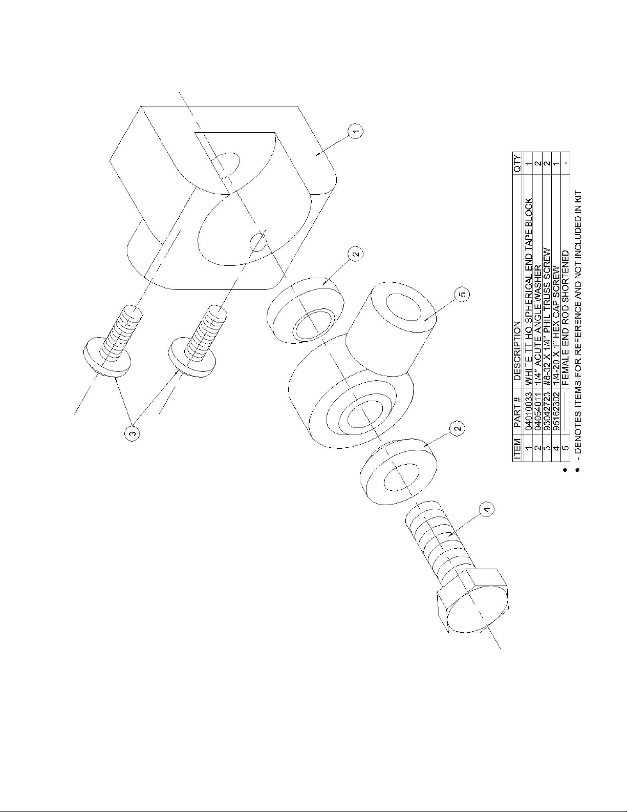
White Tape Block Kit
04221021
Parts List
Part # Description Qty.
00687011 CC Car Manual 1
04010033 White TT HO Spherical End Tape Block 1
04054011 ¼” Acute Angle Washer 1
93042723 #8-32 x ¼” Phillips Truss Screw 2
95162302 ¼-20 x 1” Hex Cap Screw 1
Tools Needed
Medium Phillips Screwdriver
7/16 Nutdriver
White Tape Block
Replacement Instructions
Please refer to the diagram on page 4 when replacing the white tape block.
1. Remove the CC Carrier (please see the drive tape removal and install instructions on page
11).
2. Use a 7/16 nutdriver and remove the ¼ - 20 hex cap screw that holds the white TT ho
spherical end tape block in place. Discard the hex cap screw.
3. Discard the old white TT ho spherical end tape block and the two ¼ acute angle washers.
4. Take the new ¼ - 20 x 1 hex cap screw and slide it through one ¼ acute angle washer, the
pivot post, and the other ¼” acute angle washer and screw it into the new white TT ho
spherical end tape block. Make sure that the ¼” acute angle washers are going in the right
direction. Tighten the ¼-20 bolt with the 7/16 nutdriver.
5. Check and make sure that the white TT ho spherical end tape block pivots freely. If it
does not, check the pivot post for damage.
6. Reattach the CC Carrier (please see the drive tape removal and install instructions on
page 11).
7. Run the unit and check for proper operation.
4

5
CC Molded Cable Block Kit
04221051
Parts List
Part # Description Qty.
00687011 CC Car Manual 1
04068012 CC Molded Cable Block ‘B’ 1
04264991 CC Carrier Retrofit Kit 1
04115011 Clear Grease 4cc Tube 1
04207991 CC Long Cable Replacement Kit 1
92042123 #6-32 x ¼” Phillips Flathead Screw 4
92042723 #6-32 x ¼” Phillips Truss Screw 10
92005002 #6-32 Nylon Locking Nut 5
93044623 #8-32 x ¼” Phil Pan Self Tapping 11
Tools Needed
Medium Phillips Screwdriver
5/16 Nutdriver
CC Molded Cable Block
Replacement Procedure
Please refer to the diagram on page 13 when replacing the molded cable blocks
1. Remove the cc carrier. Please see the drive tape removal and install instructions section
on page 11.
2. Remove the four phillips flat screws and the ten phillips truss screws that hold the carrier
backcover and cover with a medium phillips screwdriver. Remove the covers.
3. Replacing cable block A
A. Refer to the cc long cable replacement manual provided with the kit.
4. Replacing Cable Block B
A. Use a 5/16 nutdriver and remove the two #6-32 nuts that hold the B block in
place. Discard the nuts.
B. Use the clear grease provided and put a small bead inside the grooves of the new
B block.
C. Slide the cable B block back on the studs making sure that you do not pinch the
short cable under the block. The cable must be inside the slot of the cable block so
that the carrier door will open and close properly.
D. Use a 5/16 nutdriver and reattach the cable blocks with the #6-32 nylon locking
nuts provided.

6
5. Replace the C block by referring to the manual provided with the cc carrier retrofit kit.
6. Use the Carrier Latch to test the door for proper operation.
7. Mount the CC Backcover and cover the same way as you removed them in step 2. Use
the screws provided if needed.
8. Reattach the CC Carrier. Please see the drive tape removal and install instructions section
on page 11.
9. Test the unit for proper operation.

7
CC Carrier Liner Kit
04221061
Parts List
Part # Description Qty.
00687011 CC Car Manual 1
04088011 CC Liner Side 1
04088021 CC Liner Back 1
04088031 CC Liner Top and Bottom 2
55555174 .050 Short Arm Allen Wrench 1
92042123 #6-32 x ¼” Phillips Flathead Screw 4
92042723 #6-32 x ¼” Phillips Truss Screw 10
93044623 #8-32 x ¼” Phil Pan Self Tapping 11
Tools Needed
Medium Phillips Screwdriver
11/32 Nutdriver
.050 Allen Wrench (Provided)
Putty Knife
Pliers
CC Carrier Liner
Replacement Instructions
Please refer to the diagram on page 13 when replacing the carrier liners.
1. Remove the CC Carrier (please see the drive tape removal and install instructions on page
11).
2. Remove the four phillips flat screws and the ten phillips truss screws that hold the carrier
backcover and cover with a medium phillips screwdriver. Remove the covers.
3. Use an 11/32 nutdriver and a medium phillips screwdriver and remove the #8-32 phillips
truss screw that holds the hold down spring in place. Remove the hold down spring.
4. Use a pair of pliers and remove the door close spring from the bail.
5. Use the .050 allen wrench provided and remove the outside bail collar.
6. Remove the bail
7. Install the CC liner top and bottom over the old liner. Make sure you mark and punch out
the holes in the liner for the bail to go through.

8
8. Install the CC liner back over the old liner.
9. Install the CC liner side over the old liner. Mark and punch out the hole for the CC hold
down spring bolt.
10. Reinstall the bail the same way as you removed it in steps 5 and 6.
11. Reinstall the door close spring to the bail.
12. Reinstall the hold down spring the same way as you removed it in step 3.
13. Mount the Carrier Cover the same way as you removed them in step 2. Use the screws
provided if needed.
14. Reattach the CC Carrier (please see the drive tape removal and install instructions on
page 11).
15. Run the unit to check for proper operation.

9
CC Carrier Door Kit
04221071
Parts List
Part # Description Qty.
00687011 CC Car Manual 1
04062023 CC Door Arm ‘A’ 1
04062033 CC Door Arm ‘B’ 1
04063011 Door Close Spring 1
04066012 Molded CC Door Pivot 2
04097011 Door Closes Label 1
04098011 Door Opens Label 1
04115011 Clear Grease 4cc Tube 1
92015007 #6-32 Acorn Nut 4
92042123 #6-32 x ¼ Phillips Flathead Screw 4
92042723 #6-32 x ¼ Phillips Truss Head 10
93005063 #8-32 Thin Nylon Locking Nut 1
94005005 #10-32 Thin Nylon Locking Nut 2
94006004 3/16 Aluminum Backup Washer 2
94039233 3/16 x 3/16 Stripper Bolt 1
93044623 #8-32 x ¼” Phil Pan Self Tapping 11
Tools Needed
Medium Phillips Screwdriver
3/32 Allen Wrench
11/32 Nutdriver
3/8 Nutdriver
5/16 Nutdriver
Pliers
CC Carrier Door Repair Kit
Replacement Instructions
Please refer to the diagram on Page 13 when repairing the CC Carrier Door.
1. Remove the four phillips flat head screws and the ten phillips truss screws that hold the
carrier cover and back cover with a medium phillips screwdriver. Remove the covers.
2. Use a pair of pliers and remove the door close spring. Discard the spring.
3. Remove the two #10-32 locking nuts that hold the door arms to the carrier chassis.
Remove the two 3/16 aluminum backup washers. Discard the old nuts and washers.
4. Spread apart the door arms slightly and remove from the carrier chassis.

10
5. Remove the two door pivots and discard.
6. Use a 3/32 allen wrench and an 11/32 nutdriver and remove the 3/16 stripper bolt that
attaches the cc long cable to the door arm. Discard the old stripper bolt and nut.
7. Use a 5/16 nutdriver and remove the four #6-32 acorn nuts that hold the door arms to the
carrier door. Discard the old door arms and acorn nuts.
8. Mount the new door arms with the acorn nuts provided the same way as you removed
them in step 7. Please be sure you have the correct door arm on the correct side.
9. Reattach the cc long cable with the 3/16 stripper bolt and #8-32 nylon locking nut
provided the same way as you removed it in step 6.
10. Slide the two door pivots provided on the door posts.
11. Use the clear grease provided and put a small bead around the top of each door pivot.
12. Slide the carrier door in place the same way as you removed it in step 4.
13. Use the clear grease provided and put a small bead on the door arms where the door pivot
comes through.
14. Put a 3/16 aluminum backup washer provided over each door pivot.
15. Use a 3/8 nutdriver and put a #10-32 thin nylon locking nut on each carrier post. Do not
tighten the nut too tight. The carrier door needs to open and close freely.
16. Reattach the door close spring provided.
17. Activate the carrier latch to make sure the door opens and closes freely and adjust if
needed.
18. Mount the Carrier backcover and install the same way as you removed it in step 1. Use
the screws provided if needed.
19. Run the unit to check for proper operation.

11
Drive Tape Removal and Install
Instructions
Caution
Do not use tape to hold the brake release button down for long periods of time. This will cause
overheating and possible damage to the brake.
Removal of the Drive Tape
1. Remove the flat head screws that hold the speaker panel to the customer vertical tube.
The speaker and panel can hang by the speaker lead.
2. Go inside and send the carrier to the car position outside. Turn the power off on the inside
control assembly.
3. Open the right door of the inside vertical standoff. The door is hinged; removing the two
screws will allow the door to open.
4. On the front side of the tube, insert a screwdriver into a slot in the drive tape.
5. Press and hold the brake release button on the brake board.
6. Push up on the screwdriver pushing the tape up. Observe the carrier outside as it lowers.
Do not let the carrier hit the island. Do this until the drive tape disengages the drive
sprocket.
7. Go outside and remove the carrier from the drive tape with a medium phillips
screwdriver. Leave the screws in the drive tape so you know how to attach the carrier
when the repair is completed.
Install of the Drive Tape
1. Mount the carrier back on the drive tape. Make sure that the tape block holes are not
stripped. If they are, consult the factory for new tape blocks.
2. Feed the drive tape back into the unit until you feel the drive tape stop.
3. Go inside to the inside vertical and press and hold the brake release button.

12
4. Insert a screwdriver into a slot of the drive tape.
5. Push down on the screwdriver feeding the tape around the drive sprocket. Continue to do
this until the carrier is resting on the stabilizers outside. Be careful that the carrier is not
caught on the speaker lead.
6. Turn the power back on and recall the carrier.
7. Run the unit and observe for proper operation. Note: if the carrier started out above the
stop switches, it will not shift into high speed. Simply run the carrier again and it should
shift speeds.
8. Adjust the shift points if needed.
9. Replace the speaker panel on the customer vertical.
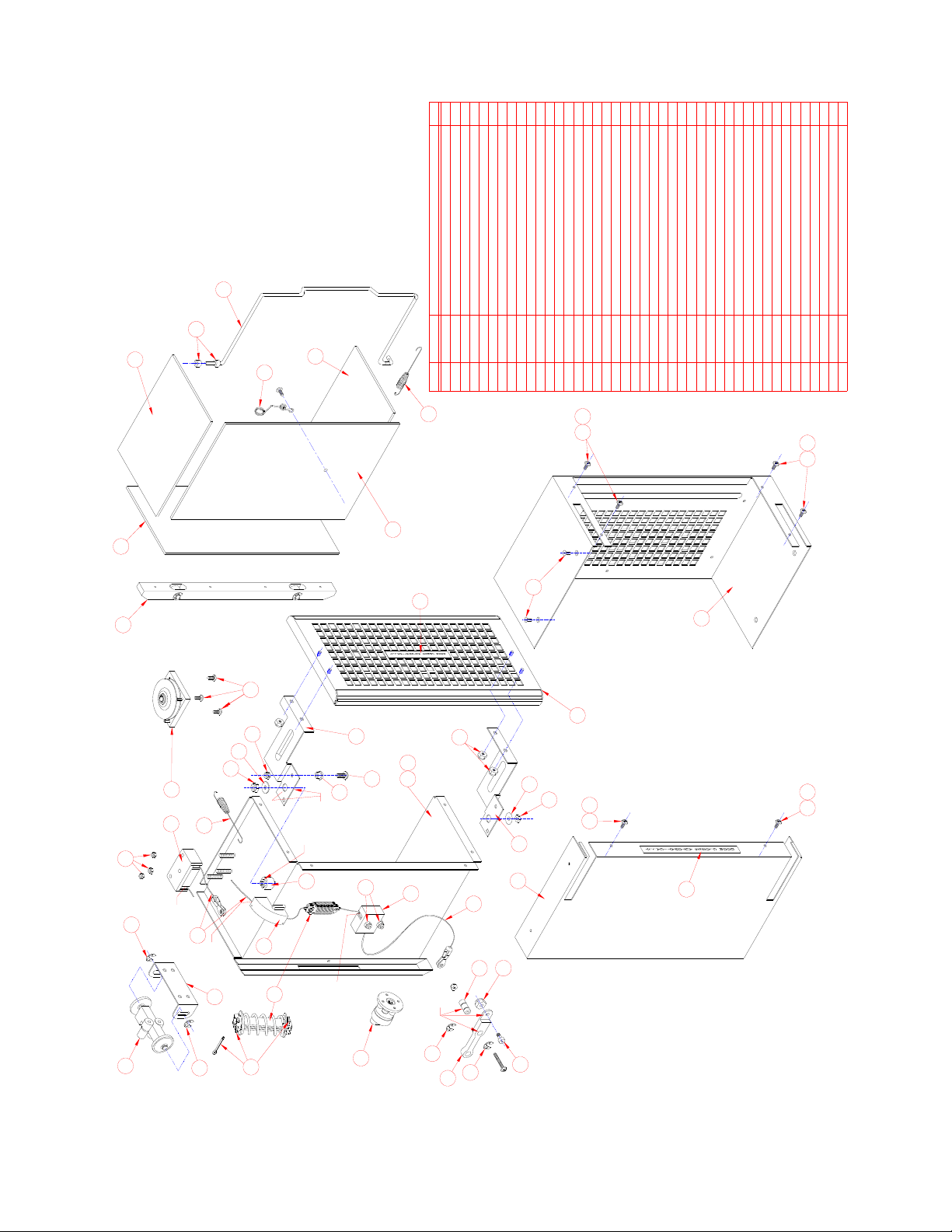
94005005 #10-32 THIN NYLON LOCKING NUT 26 3/16 ALUMINUM BACKUP WASHER
17
15
16
14
10
12
13
11
9
94006004
8
7
2
1
2
CC MOLDED DOOR PIVOT
#6-32 ACORN NUT
ITEM
1 04062033 DOOR ARM 'B'
DOOR ARM 'A'
040660123
920150075
4
040620232
DESCRIPTIONPART # 1
2
4
2
1
QTY
LUBE
10
10
16
8
9
10
14
15
10
11
6
2
1
7
5
3
4
12
3/16 X 3/16 STRIPPER BOLT
CC CAR BACKCOVER
CC LONG CABLE
CC MOLDED CABLE BLOCK 'A'
CC ARTICULATED CAR CHASSIS
#6-32 X 1/4 PHILIPS FLATHEAD SCREW
#6-32 X 1/4 TRUSS HEAD SCREW
92042123
92042723 14
4
DOOR CLOSE SPRING
04063011
#8-32 HEX THIN NYLON LOCKING NUT
18
19
13
DOOR CLOSES LABEL
04097011 1
04098011 DOOR OPENS LABEL 1
CC CARRIER COVER
LUBE
17
18
19
6
7
CC MOLDED CABLE BLOCK 'C'
LUBE
LUBE
LUBE
LUBE
9
35
21
20 CC MOLDED CABLE BLOCK B
DOOR OPEN SPRING ASSEMBLY
CC SHORT CABLE
22
23 CABLE PULLEY RETROFIT
04069021
04068012
04254991
04220991
1
1
1
1
1
1
1
1
1
1
20
21
22
OR
93005063
23
NEWER VERSION
(ENLARGED VIEW)
04069011
26
25
27
27
4
30
28
29
04059011
04078011
04060991
16a CC CAR CHASSIS 104060992
04080012
04067012
94039233
10a #6-32 X 1/4 TRUSS HEAD SCREW
93044623 11
10a
10a
16a
10a
10a
24 CC DOOR W/ROUNDED CORNERS
25
26
28
27 CC HOLD DOWN SPRING
5/32IN PLATED BRASS COLLAR
29
30 PC BAIL WITH HOLES
04105021
04081991
93046006
2
1
1
2
1
1
1
04062014
24
CC LINER SIDE
CC LINER TOP AND BOTTOM
CC LINER BACK
04088011
04088021
04088031
31 CC CARRIER LATCH
1/16 X 1/2 CC COTTER PIN
32
33 6-32 NYLON LOCKING NUT
04053996
92005002
90088003
1
5
2
33
31
10
32
32
NOTE - QUANTITY IN KIT MAY VARY
3/16 ID FLANGED BUSHING
34 04312011 1
#8-32 X 1/2 PHILIPS TRUSS SCREW SS
35 93082723 1
34
1/4" E CLIP ZINC
36
37 LARGE TAPE BLOCK KIT
04203991
95005071 1
4
TT WIDE TAPE BLOCK BRACKET
38 04055011 1
SPHERICAL TAPE BLOCK ASSEMBLY
39 04189991 1
39
38
36
37
37
40
CC CARRIER LATCH BUSHING
40 04095022 1
37
37
41
CC ROLLER RUNNER ASSEMBLY
41 04241991 1
13

Table of contents


