Baxall ZR-DC/WBX User manual

Please read this manual before installing your receiver
ZR-DC/WBX DC Receiver
Installation Instructions

Page 2
ZR-DC/WBX Installation and Operating Instructions
IMPORTANT
The first few pages of these instructions contain important information on safety and product
conformity. Please read, and ensure that you understand this information before continuing.

Page 3
Installation and Operating Instructions ZR-DC/WBX
CONTENTS
Product Safety ........................................................................................................................................................................................... 4
Electromagnetic Compatibility (EMC) .................................................................................................................................................. 4
Manufacturers Declaration of Conformance .................................................................................................................................... 4
General connector layout ............................................................................................................................................................................ 5
Introduction ................................................................................................................................................................................................... 6
Unpacking ..................................................................................................................................................................................................... 6
Mounting ....................................................................................................................................................................................................... 6
Supply Connections ..................................................................................................................................................................................... 6
Connecting the Pan/Tilt head and Auxiliaries ............................................................................................................................................... 7
Connecting the Lens .................................................................................................................................................................................... 8
Connecting the Preset Feedback Potentiometers ........................................................................................................................................ 8
Pan and Tilt head feedback potentiometers ................................................................................................................................................ 9
Connecting the Telemetry ........................................................................................................................................................................... 10
Connecting the Video ................................................................................................................................................................................. 10
Connecting the Alarm Inputs ...................................................................................................................................................................... 10
Connecting the Alarm Output Relay ........................................................................................................................................................... 10
Switch Settings - Lens ............................................................................................................................................................................... 11
Switch Settings - Auxiliary output relays .................................................................................................................................................. 11
Switch Settings - Creep Speed .................................................................................................................................................................. 12
Switch Settings - Auto Pan or Tour ........................................................................................................................................................... 12
Testing and Commissioning ........................................................................................................................................................................ 13
Testing the Video and Telemetry Reception .............................................................................................................................................. 13
Video Gain and Lift Adjustment .................................................................................................................................................................. 13
Testing the Pan/Tilt head, Lens and Presets ............................................................................................................................................. 14
Setting up the Presets ................................................................................................................................................................................ 14
FUSE Replacement ..................................................................................................................................................................................... 14
Specifications ............................................................................................................................................................................................. 15

Page 4
ZR-DC/WBX Installation and Operating Instructions
PRODUCT SAFETY
Please follow these instructions as you install your ZR-DC/WBX and retain them for its lifetime. If you encounter any
problems contact Baxall Limited.
IMPORTANT NOTE
The power supplies in your ZR-DC/WBX receiver are designed to power the receiver itself and to provide outputs for
lens drives, pan and tilt drives etc. Under no circumstances should any other equipment such as cameras, heaters,
fans, interface converters etc. derive their power directly from your ZR-DC/WBX receiver. Incorrect use of the
receiver in this manner may cause damage and invalidate your warranty.
Installation is only to be carried out by competent, qualified and experienced personnel. Wire in accordance with the
country of installations National Wiring regulations. Failure to do so can result in death or injury by electric shock. A
means of disconnecting the receiver from the mains supply must be provided as part of the installation and must be
situated close by.
BEFORE UNDERTAKINGANYINSTALLATION OR MAINTENANCE, THE RECEIVER MUST BE DISCONNECTED FROM THE
MAINS SUPPLY.
Your ZR-DC/WBX is designed for use in a general purpose CCTV installation and has no other function. Do not exceed
the voltage and temperature limits given in the specifications. Only use your ZR-DC/WBX in a clean, dry, dust-free
environment unless a suitable protective housing is provided.
To prevent access by unauthorised personnel, tighten the four lid securing screws on the weatherproof enclosure
with a suitable tool until they cannot be undone by hand. Do not exceed a torque of 4Nm.
ELECTROMAGNETIC COMPATIBILITY (EMC)
This is a Class A product. In a domestic environment this product may cause radio interference in which case the
user may be required to take adequate measures.
This product is intended solely for use in general purpose CCTV applications.
The product must be installed and maintained in accordance with good installation practice to enable the product to
function as intended and to prevent problems. Refer to Baxall Limited for installation guidance.
MANUFACTURERS DECLARATION OF CONFORMANCE
The manufacturer declares that the equipment supplied with this manual is compliant with the essential protection
requirements of the EMC directive 89/336 and the Low Voltage Directive LVD 73/23 EEC. Conforming to the requirements
of standards EN 55022 for emissions, IEC801 parts 2, 3 and 4 for immunity and EN 60950 for Electrical Equipment
safety.

Page 5
Installation and Operating Instructions ZR-DC/WBX
GENERAL CONNECTOR LAYOUT
Shown below are the locations of the connectors, switches, LEDs fuses etc. on the main and preset printed circuit
boards. Although shown separately for clarity, the preset PCB is usually mounted above the main PCB in the position
indicated by the dotted line.
Figure 1
Page 6
ZR-DC/WBX Installation and Operating Instructions
INTRODUCTION
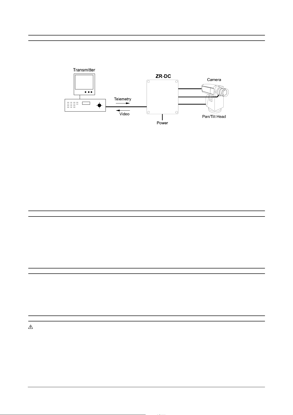
The diagram below shows an example of a telemetry system. Your ZR-DC/WBX receiver is a Closed Circuit TV (CCTV)
component which receives instructions from a remote transmitter and translates them into Pulse Width Modulated
(PWM) DC control signals and DC lens drive signals.
Your ZR-DC/WBX receiver takes as its control input a Baxall 20mA twisted-pair telemetry signal or a Baxall coaxial
telemetry signal (where telemetry signals and video signals share the same coaxial cable). The ZR-DC/WBX can drive
a DC Pan/Tilt head, four auxiliaries and three lens functions (zoom, focus and iris).
Your ZR-DC/WBX can store eight preset positions, each with an associated alarm input. Also linked to the alarm inputs
is a volt-free alarm output relay which closes for one second for each new alarm condition. In addition, a software driven
auto pan or preset tour function is provided.
Note: In order for the auto pan and preset tour functions to operate correctly, the video from the camera must be routed
through the receiver PCB.
Your ZR-DC/WBX also contains a video amplifier, with gain and high-frequency lift. This can improve video transmission
and telemetry reception over longer cable runs.
The ZR-DC/WBX contains a 240V AC to 24V DC power supply which powers the circuit board and a 24V DC Pan/Tilt head.
UNPACKING
Keep your packaging for use if your DC receiver is stored for a time or needs to be returned for whatever reason. The
packaging should contain:
The ZR-DC/WBX receiver
These instructions
Please inform your suppliers and carriers immediately if the product is damaged or any part is missing. Do not attempt
to use it.
MOUNTING
Your ZR-DC/WBX must be permanently and securely fixed at its intended location. Ensure that the mounting surface is
flat to avoid distorting the box and compromising the seals. The ingress protection (IP) rating of the supplied enclosure
is IP65. In order that this is not compromised, suitable cable glands must be used to facilitate cable entry and must be
fitted in accordance with the manufacturers instructions. Cable entry into the enclosure must permit free access to all
other parts for the purposes of maintenance. Cable entry must not obstruct any warning labels or interfere with the correct
operation of the device.
SUPPLY CONNECTIONS
WARNING
SWITCH OFF ALL THE POWER BEFORE CONNECTING THE RECEIVER. YOUR RECEIVER MUST BE EARTHED. THE
PROTECTIVE EARTH CONNECTION MUST BE MADE BEFORE CONNECTING MAINS VOLTAGES. A MEANS OF
DISCONNECTING THE RECEIVER FROM THE MAINS SUPPLY MUST BE PROVIDEDAS PART OF THE INSTALLATIONAND
MUST BE SITUATED CLOSE BY.
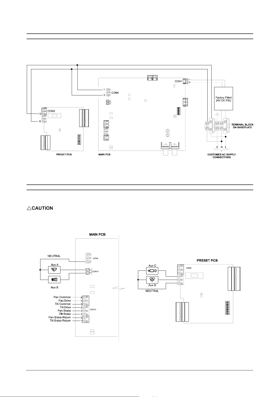
Your ZR-DC/WBX requires connection to a 240V AC supply in accordance with good installation practice. The internal
power supply connections are made at the factory. Ensure that the power is switched off. Connect the power wires to
the EARTH (E), NEUTRAL (N) and LIVE (L) terminals on the terminal block fixed to the metal base plate. Ensure that the
incoming power connections are on the opposite side of the terminal block from all the internal connections so that the
Page 7
Installation and Operating Instructions ZR-DC/WBX
SUPPLY CONNECTIONS
LIVE connections pass through the fuses provided. The 240V AC connection, in addition to operating the 24V DC PSU,
can be switched by internal relays to supply any auxiliary devices operated by the system.
Typical Connections
CONNECTING THE PAN/TILT HEAD AND AUXILIARIES
Referring to the instructions for your Pan/Tilt head and auxiliaries, connect them according to the schematic below. The
Auxiliaries A, B, C and D may be configured using SW1 and SW2. They are shown in the schematic in their default states.
Maximum current is 750mA per relay. Infrared lamps will exceed this so an external slave relay will be neccessary.
Page 8
ZR-DC/WBX Installation and Operating Instructions
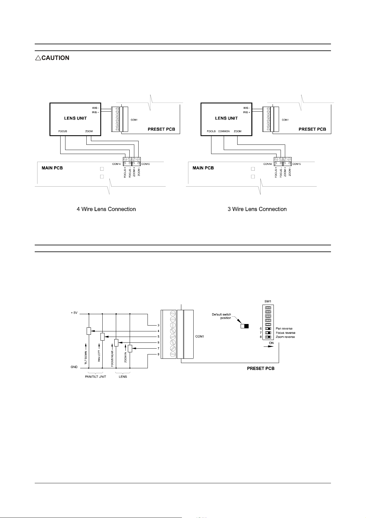
CONNECTING THE LENS
DO NOT CONNECTANY LENS CONNECTIONS TO GROUNDAS THIS MAY DAMAGE YOUR ZR-DC/WBX. IN PARTICULAR,
ENSURE THAT THE LENS COMMON ON A3 WIRE LENS CONNECTION IS NOT CONNECTED TO GROUND.
Switch SW2 on the main PCB needs to be set to the type of lens being used - see Switch Settings - Lens Type
CONNECTING THE PRESET FEEDBACK POTENTIOMETERS
The diagram below shows the default direction for the feedback pots. For example, it shows that as the lens is focused
on a nearby object, the focus feedback signal increases towards +5V. The focus, zoom and pan directions can easily be
reversed using switches 6, 7 and 8 (SW1) on the preset PCB. Changing the tilt feedback direction is slightly more
complicated so try to wire it correctly now e.g. so that tilt down increases the feedback voltage towards +5V. Refer to the
instructions for your lens and Pan/Tilt unit to wire the feedback pots.
The switches SW1/6, SW1/7 and SW1/8 can be used to reverse the operation of the Pan, Focus and Zoom functions
simply by changing the switch to its opposite position.
Page 9
Installation and Operating Instructions ZR-DC/WBX
PAN AND TILT HEAD FEEDBACK POTENTIOMETERS
DANGER OF ELECTRIC SHOCK. SWITCH OFF POWER BEFOREALTERINGANY PAN AND TILT HEAD CONNECTIONS
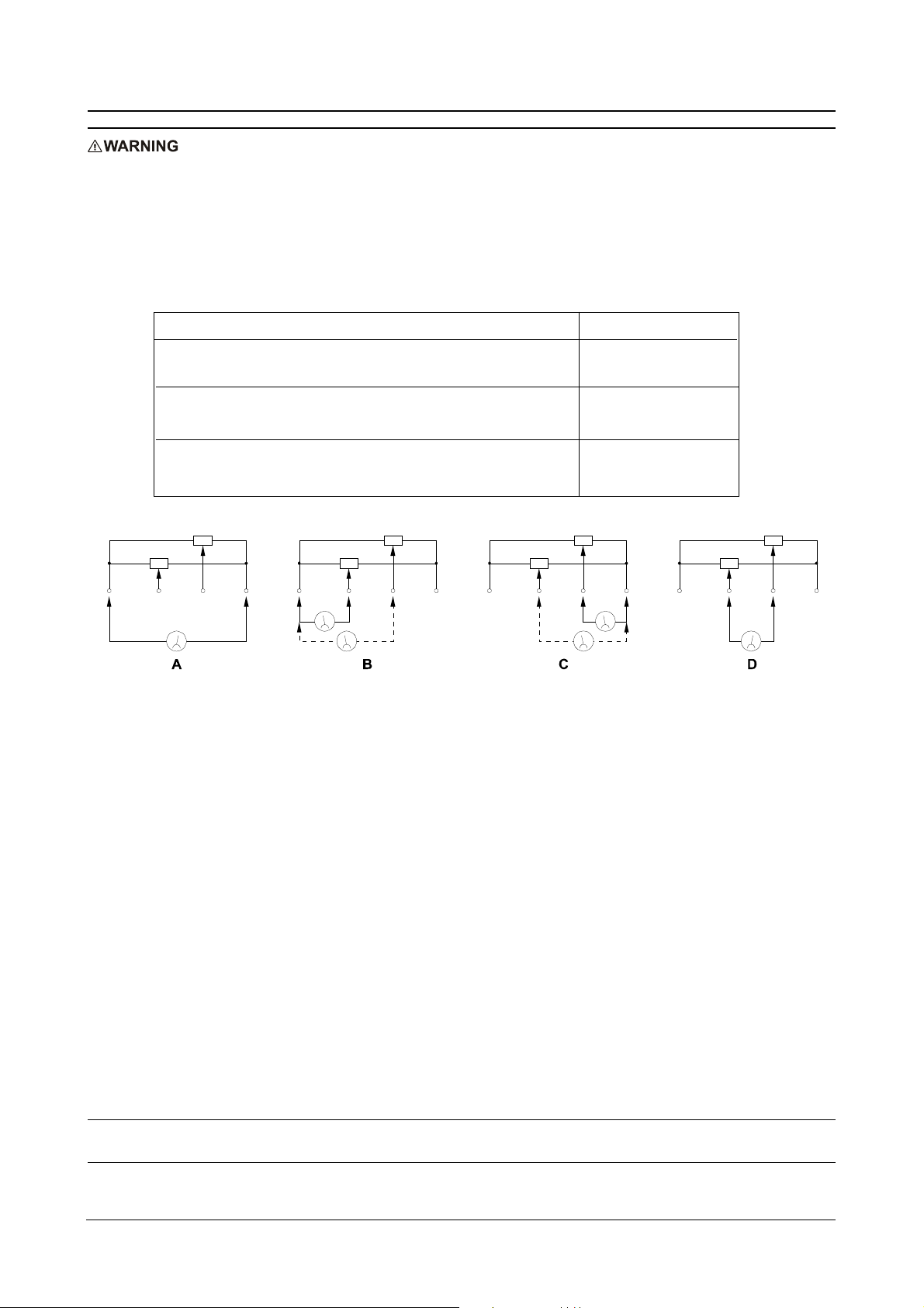
Determining the supply connections
The supply connections to the feedback potentiometers can be identified using a Digital Voltmeter (DVM) set to measure
resistance as follows.
Connect the DVM to any two of the four wires. Actuate both the pan and tilt functions and observe the changes in the
resistance readings of the DVM. The DVM will be connected according to the table below.
Observations Connection
No resistance change when both
pan and tilt are actuated
Resistance reading is changed by pan or tilt
actuation (not both)
Resistance reading changes when
both pan and tilt are actuated
When the DVM is connected according to A above, the supply wires have been correctly identified. Connect the supply
wires to the preset PCB as follows: Positive supply wire to CON 1 terminal 3, Negative supply wire to CON 1 terminal 8.
Determining the pan and tilt potentiometers
Connect the DVM to one of the remaining two wires and the negative supply connection. Actuate the pan function only and
see if the measured resistance changes. If the resistance changes, the wire is connected to the pan feedback potentiometer,
if it doesnt, the wire is connected to the tilt potentiometer. Confirm this by actuating the tilt function and checking the
resistance changes with respect to the negative supply connection. Connect the wires to CON 1 according to the
following: Pan potentiometer to terminal 5, Tilt potentiometer to terminal 4.
Checking correct feedback potentiometer operation
Set the DVM to measure voltage (e.g. 0 to 20V DC) and connect it across the negative supply connection and the tilt
potentiometer connection (CON 1 terminal 8 and CON 1 terminal 4) Operate the tilt function. The voltage measured
should decrease towards 0V as the pan and tilt head is tilted up, and towards 5V as the head is tilted down. If the opposite
occurs, the supply connections are probably incorrect. Exchange the CON 1 terminal 3 and CON 1 terminal 8 connections
with each other.
Next, check the pan function by connecting the DVM across the negative supply and pan potentiometer terminals (CON
1 terminal 8 and CON 1 terminal 5). As the head is panned to the left, the voltage measured should increase towards 5V.
As the head is panned to the right, the voltage measured should decrease towards 0V. If the opposite occurs, use the
mode reversal switch on the preset PCB (SW1, switch 6) to reverse the pan function operation. Note that the switch won't
affect the voltage measured, instead it changes the way the receiver interprets the feedback voltage swing.
Testing
Set up a preset position using the telemetry transmitter according to its instructions, and check the operation and
accuracy of the preset. If all is well, use the same methods to determine the zoom and focus feedback connections.
Note: If after making the zoom and focus connections both the pan and tilt feedback potentiometers do not operate
correctly, try reversing the lens feedback supply connections.
A
B or C
D

Page 10
ZR-DC/WBX Installation and Operating Instructions
CONNECTING THE TELEMETRY
You can use either coaxial or twisted pair telemetry with your ZR-DC/WBX. It switches automatically to the type of telemetry
it first receives after the power is applied.
Twisted-pair Telemetry
Connect Baxall 20 mA twisted pair telemetry to CON 3 on the main PCB. Either polarity is accepted.
Coaxial Telemetry
Baxall coaxial telemetry is connected as the video connections are made. Note that you can still connect the video through
the PCB if you use twisted-pair telemetry.
CONNECTING THE VIDEO
Connect all video using 75 ohm video coaxial cable terminated by BNC connectors. Connect the camera to VIDEO IN, and
the transmitter to VIDEO OUT.
Note: In order for the auto pan and preset tour functions to operate correctly, the video from the camera must be routed
through the receiver PCB.
CONNECTING THE ALARM INPUTS
Your ZR-DC/WBX has 8 alarm inputs. The alarm inputs are split into two banks. Alarm inputs 1 to 4 are always configured
as normally open (N/O). Alarm inputs 5 to 8 are configured as normally open unless the select terminal (SEL) is
connected to ground. In this case they become normally closed (N/C).
Note: When AL5 to AL8 are configured as normally closed, any unused alarm inputs must be connected to ground to
ensure correct operation.
CONNECTING THE ALARM OUTPUT RELAY
A normally open, volt-free relay contact is provided for alarm output purposes. This relay contact closes for approximately
one second for each new alarm condition. The relay is rated for a maximum of 3A at 240V AC.
Page 11
Installation and Operating Instructions ZR-DC/WBX
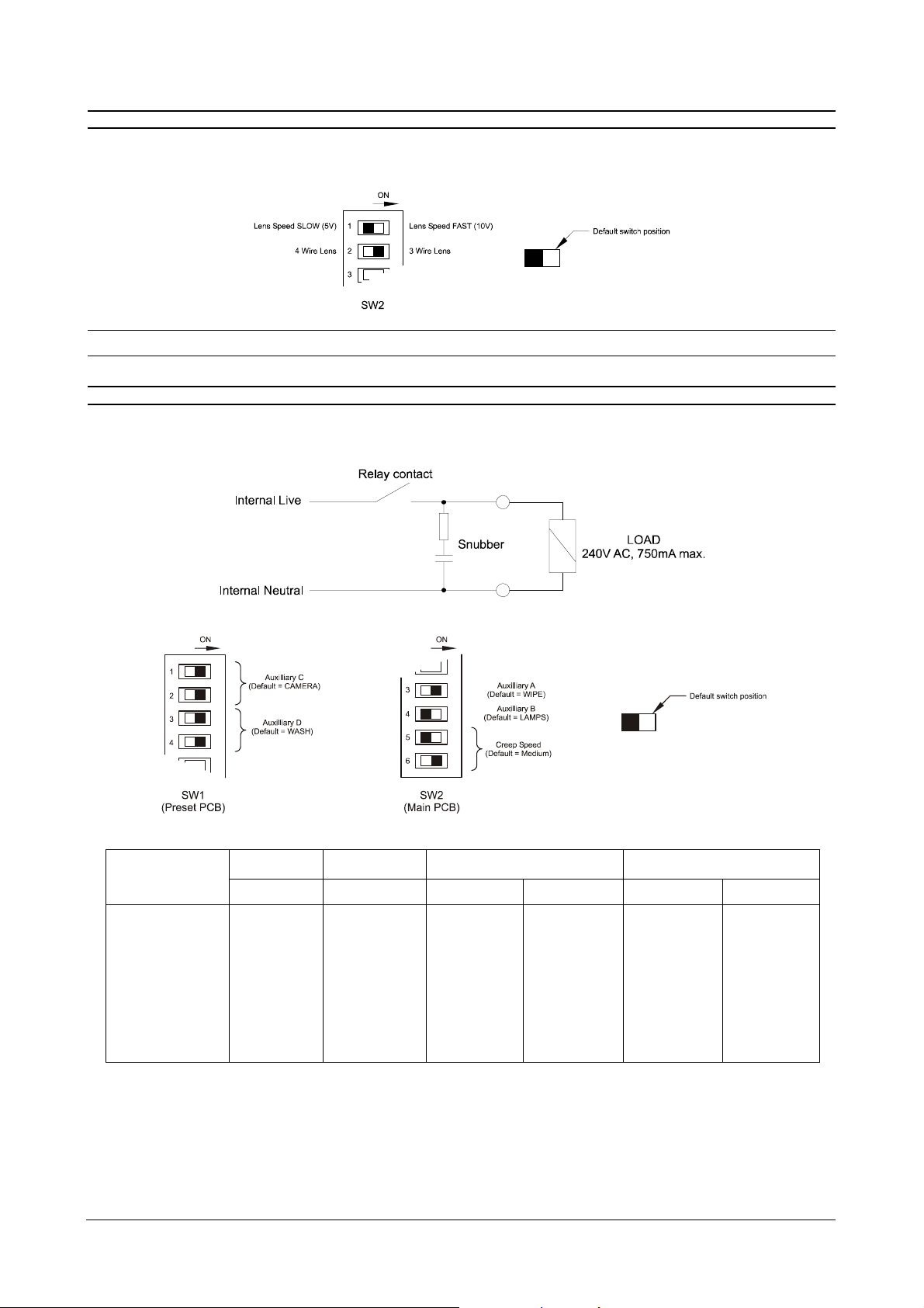
SWITCH SETTINGS - LENS
Switches 1 and 2 of the 6 way dip-switch, SW2 control the Lens speed and the lens type as shown below. The switch is
located on the main PCB.
Note: The iris is independent of whether a 4 wire or 3 wire lens is selected, and also the speed setting of the lens.
SWITCH SETTINGS - AUXILIARY OUTPUT RELAYS
The AUX A, AUX B, AUX C and AUX D relays can be programmed to respond to camera power, wipe, lamps, wash or Aux
4 telemetry commands from the transmitter. The contact configuration is shown below.
Notes: *indicates default setting.
this function remains on for as long as the key is held.
this function toggles between off and on.
Convention SW2/3 = Switch number 3 of dip switch bank SW2.
Function AUX A AUX B AUX C AUX D
SW2/3 SW2/4 SW1/1 SW1/2 SW1/3 SW1/4
Camera On - Off * Off * - -
Wipe Off * - Off On Off On
Lamps - On* On Off - -
Wash - Off On On Off * Off *
AUX4 -- --OnOff
AUX4 -- --OnOn

Page 12
ZR-DC/WBX Installation and Operating Instructions
SWITCH SETTINGS - CREEP SPEED
Four creep speeds are available for preset recall. When the preset has been recalled, it will ramp up to its top speed then
decelerate to the selected creep speed as it approaches the final preset position. Use Switches 5 and 6 of the 6 way dip-
switch, SW2 to select the creep speed. Default setting is Medium.
If the Pan/Tilt head stalls on preset recall, increase the creep speed. If the Pan/Tilt head overshoots, decrease the creep
speed.
SWITCH SETTINGS - AUTO PAN OR TOUR
When auto pan (AUX 3) is selected at the transmitter the standard ZR-DC/WBX can operate in one of two pan modes, auto
pan or Tour. Auto pan is a software driven function and so does not need a specialised pan and tilt unit. When you operate
auto pan the Pan/Tilt head pans for 60 seconds, pauses 15 seconds, pans in the opposite direction, pauses and starts
again. If your Pan/Tilt head hits the end-stops, it rests there until the auto pan asks it to return. The Tour function needs
feedback potentiometers in the pan and tilt head. It performs a tour of all the stored preset camera positions in numerical
order. Preset positions must be defined and stored for the tour function to operate correctly. The default setting is for auto
pan.
Note: On some transmitters, when auto pan is operating, you must first deselect it before manual control can be regained
over the telemetry.
Creep Speed Switch 2/5 Switch 2/6
Slow Off Off
Medium Slow Off On
Medium On * Off *
Fast On On
*indicates default setting.
Page 13
Installation and Operating Instructions ZR-DC/WBX
TESTING AND COMMISSIONING
MAINS VOLTAGES MAY NOW BE PRESENT. THERE IS ARISK OF INJURY OR DEATH BY ELECTRIC SHOCK.
Check that all connections to your ZR-DC/WBX are correct then switch on the power to your camera, transmitter and ZR-
DC/WBX.
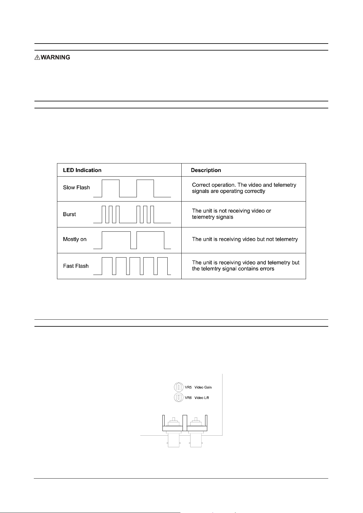
TESTING THE VIDEO AND TELEMETRY RECEPTION
Your ZR-DC/WBX switches to the type of telemetry it first receives when the power is switched on. You can still use the
video connections if you are using twisted-pair telemetry.
The Telemetry and Video Status LED located on the main PCB (see figure 1) is used to check that both the video and
telemetry signals are correct. Correct operation is indicated by a slow regular flash. Other fault conditions are shown
below.
If the video signal level is too low when it arrives at the transmitter then the telemetry can lose synchronisation causing
DATA ERRORS. To remedy this, adjust the video gain and lift potentiometers as shown below.
VIDEO GAIN AND LIFT ADJUSTMENT
Adjustments to the Gain and Lift potentiometers can improve picture quality on the monitor and/or improve coaxial
telemetry reception. VR5 is used to adjust the video Gain and VR6 is used to adjust the video Lift. These are factory set
to 1 V pk-pk. If you have data errors, try adjusting Gain and Lift to improve the picture quality. When your ZR-DC/WBX is
receiving correct telemetry, the Telemetry and Video Status LED will emit a slow regular flash. The location and default
setting of VR5 and VR6 is shown below.
Page 14
ZR-DC/WBX Installation and Operating Instructions
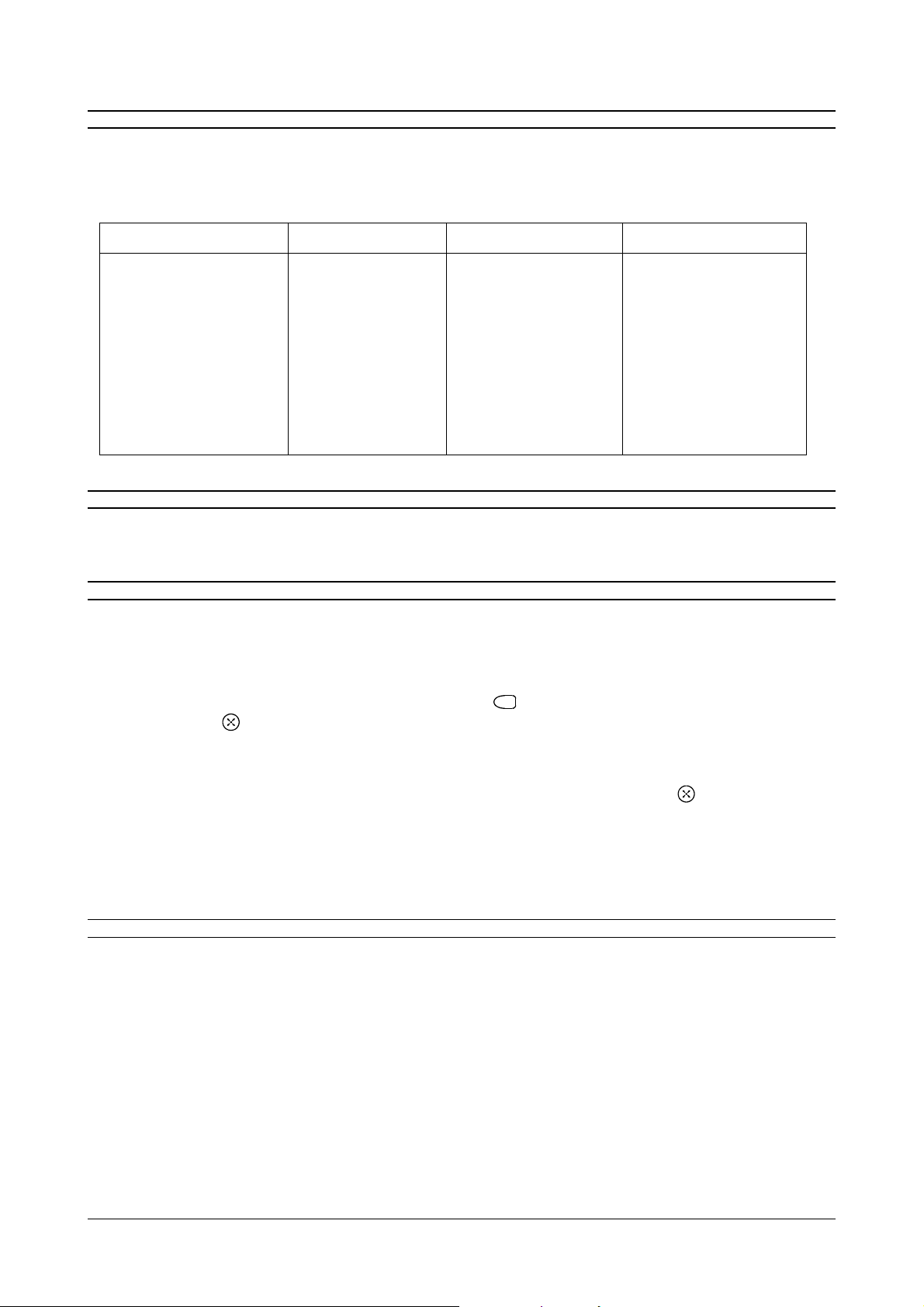
TESTING THE PAN/TILT HEAD, LENS AND PRESETS
The Test Button shown in figure 1 controls the 14 tests. Push and release the button once to enter test 0. Push and
release again to increment through each of the tests. The receiver will automatically leave test mode 30 seconds after the
last depression of the push-button or after Test 13. While you are in test mode, the Telemetry and Video Status LED
remains lit.
Test Number Action Test Number Action
Test 0 Pan Left Test 9 Wipe
Test 1 Pan Right Test 10 Camera
Test 2 Tilt Up Test 11 Lamps
Test 3 Tilt Down Test 12 Aux 4
Test 4 Zoom Out Test 13 Preset 1
Test 5 Zoom In Test 14 Preset 2
Test 6 Focus Out Test 15 Preset 3
Test 7 Focus In Test 16 Preset 4
Test 8 Wash
TESTING THE PAN/TILT HEAD, LENS AND PRESETS
It is only necessary to test one of the preset positions to ensure that the feedback connections are correct. If they are not
then they can be changed by using switches 6, 7, and 8 according to the next section.
SETTING UP THE PRESETS
Most Baxall transmitters access and set the presets by the following method, however on some transmitters the presets
can be accessed directly (see your transmitter manual).
1. Move the pan/tilt head to the desired position for this preset.
2. Store the position as preset <n> using the appropriate method for the transmitter or keyboard being used. This is
normally done by pressing the following keys in sequence:
F
(the function key), <n> (a number for the preset
between 1 and 8), (the preset key).
3. Further preset positions may be stored by repeating step 2 above.
4. Preset positions are recalled using the appropriate method for the transmitter or keyboard being used. This is
normally done by pressing the number of the preset position to be recalled followed by the preset key.
5. Programmed presets can be easily verified by activating the corresponding alarm input, e.g. activating alarm input 5
will recall preset 5.
A link on the preset board (the 2 pin jumper CON 4 shown in figure 1) allows you to disable the presets. When the jumper
is shorted, the presets are disabled.
FUSE REPLACEMENT
ZR-DC/WBX - Supply fuses
The two separate incoming live supply connections are independently fused. The fuse characteristics are clearly
marked on the label adjacent to the supply terminals. When replacing or removing both fuses, ensure that the two
fuses are not inadvertently refitted in the incorrect supply line. If either should fail, the fuse must be replaced with one
of identical value and characteristics as follows.
1. DISCONNECT THE SUPPLY.
2. Pull the appropriate black plastic fuse holder from the terminal block which is fixed to the metal baseplate.
3. Replace the fuse with the correct type and value.
4. Replace the fuse holder and reconnect the supply.

Page 15
Installation and Operating Instructions ZR-DC/WBX
FUSE REPLACEMENT
ZR-DC/WBX - Preset board fuse
The preset PCB is fitted with a protective fuse. If the fuse should fail, it must be replaced with one of identical value and
characteristics as follows.
1. DISCONNECT THE SUPPLY.
2. Pull the plastic fuse carrier from the fuse holder located on the PCB.
3. Replace the fuse with a 3.15A, anti-surge, 20mm cartridge type.
4. Replace the fuse holder and reconnect the supply.
SPECIFICATIONS
Power Supply
The ZR-DC/WBX contains a 240V AC to 24V DC ± 10% power supply.
Telemetry Inputs
Baxall Coaxial Telemetry or 20mA current loop twisted pair to the Baxall Telemetry specification.
Video Input
1V peak to peak composite video via 75 ohm BNC connector
Video Output
1V peak to peak composite video (factory set default) via 75 ohm BNC connector
Maximum gain +6dB
Maximum lift +12dB at 5MHz
Relay Contact
Auxiliaries A, B, C and D: 240V AC at 750mA maximum
Alarm Output relay: 240V Ac at 3A maximum
Lens Motor drive outputs
Selectable between 5V DC and 10V DC at 100mA. Outputs have a 1 second slow start.
Temperature Specifications
Operational Temperature: -10OC to +50OC
Humidity: 10% to 80% (non-condensing)
Storage Temperature: -20OC to +60OC
Storage Humidity: 10% to 95% (non-condensing)
Dimensions
ZR-DC/WBX: 280 x 280 x 130 mm
Weight
ZR-DC/WBX: approx. 2kg

HB-ZR-DC-5 Issue 5 10/00
Baxall Limited, Stockport, England. Visit our Web site: http://www.baxall.com
Baxall Limited reserve the right to make changes to the product and
specification of the product without prior notice to the customer.
Popular Receiver manuals by other brands


Ultra Plus
Ultra Plus X-9200HD PVR user manual

One Forall
One Forall SV-1715 instruction manual

HTRONIC
HTRONIC HT1E user manual

Audio Control
Audio Control BVR-25 Installation and operation manual

RF Technology
RF Technology R220 Operation and maintenance manual

Silvercrest
Silvercrest SL 65 T operating manual


