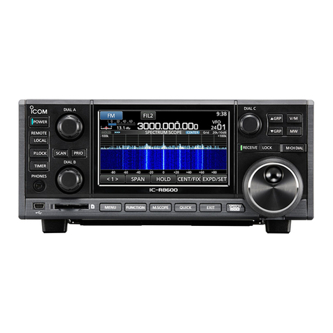
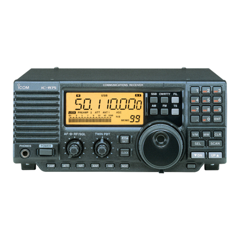
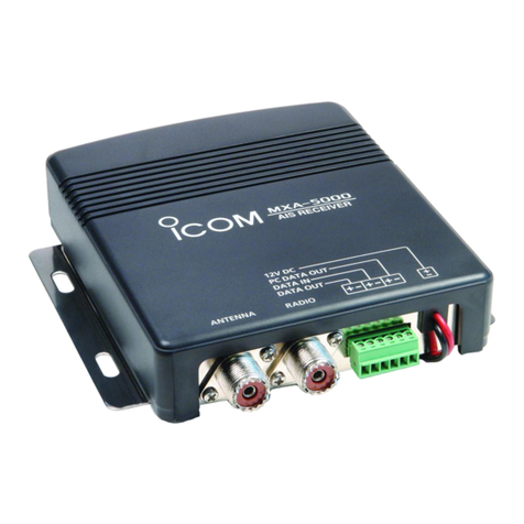
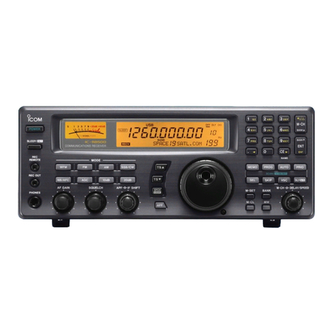
Icom IC-R8600 User manual

I/Q OUTPUT REFERENCE GUIDE
iR8600
COMMUNICATIONS RECEIVER

Table of contents
11
I/Q SIGNAL —————————————————————— 2
■General………………………………………………… 2
DGeneral description ………………………………… 2
■Communication through the [I/Q OUT] port …… 3
DGeneral description ………………………………… 3
DAbout the GUID …………………………………… 3
DAbout the endpoint ………………………………… 3
■About the I/Q signals ……………………………… 4
DGeneral description ………………………………… 4
■I/Q data details ……………………………………… 5
D24-bit long I/Q data ………………………………… 5
D16-bit long I/Q data ………………………………… 5
DRemarks …………………………………………… 6
■Control commands ………………………………… 7
DGeneral description ………………………………… 7
DCommand format …………………………………… 7
■Usable control commands ………………………… 9
DCommand description ……………………………… 9
■Control commands relative to I/Q port setting 10
DReceive frequency ……………………………… 10
DReceive Band edge frequency ………………… 10
DI/Q Output setting …………………………………11
■Operations while the IC-R8600 is in the I/Q mode
13
DOperation limitations in the I/Q mode ………… 13

I/Q SIGNAL
2
DGeneral description
You can get I/Q signals from the [I/Q OUT] port on the IC-R8600 by connecting the IC-R8600 and a PC, with a
USB cable. You can receive I/Q signals and control the IC-R8600, through the USB cable.
Requirement:
• IC-R8600 rmware must be version 1.3 or later.
• Windows 7 /8.1/10 PC (32 bit or 64 bit)
• USB 2.0 or higher
• USB I/Q driver (
USB I/Q Package for HDSDR
)
You can download it from the Icom web site.
(The software is commonly used with HDSDR*.)
*An SDR receive software (freeware). You can download it from: http://www.hdsdr.de/
I/Q signal specications:
Sampling frequency Bit depth Signal Bandwidth
16-bit 24-bit
5.12 MHz Yes N/A 4.48 MHz
3.84 MHz Yes Yes 3.31 MHz
1.92 MHz Yes Yes 1.63 MHz
960 kHz Yes Yes 815 kHz
480 kHz Yes Yes 408 kHz
240 kHz Yes Yes 203 kHz
■General
(Ver.1.30 or later)
IC-R8600
[I/Q OUT]port
PC
[USB]port
(USB3.0/USB2.0)
Windows 10 (32/64 bit)
Windows 8.1 (32/64 bit)
Windows 7 (32/64 bit)
Driver
• I/Q data
•Control command
USB cable

DGeneral description
I/Q signals and IC-R8600 control commands are exchanged through the [I/Q OUT] port on the IC-R8600.
DAbout the GUID
The GUID, that is needed to open the [I/Q OUT] port, is shown below.
68D5F5EE - B0E7 - 49FD - A0D5 - 5B10842656B7
DAbout the endpoint
The IC-R8600 has 3 endpoints. Each endpoint is reserved to receive I/Q data, to send control commands to
the IC-R8600 and to receive the acknowledgement from the IC-R8600.
The communications are done through WinUSB. To use WinUSB, you need to install the driver (USB I/Q
Package for HDSDR) that can be downloaded from Icom web site.
After the driver is installed, you can receive I/Q signals and control the IC-R8600 through the WinUSB, using
an I/Q receive software (user supplied).
To use WinUSB, you need to set the driver’s GUID and appropriate “endpoint.” Refer to the next topic for
details about them.
■Communication through the [I/Q OUT] port
Details of each endpoint:
*IN: Data from IC-R8600 to PC, OUT: Data from PC to IC-R8600
Address
(Hexadecimal) Direction* Endpoint Number
(Hexadecimal) Transfer Type
I/Q Data
IC-R8600 → PC 86 IN 06 Bulk transfer
Control command
IC-R8600 → PC 88 IN 08 Bulk transfer
Control Command
PC → IC-R8600 02 OUT 02 Bulk transfer
IC-R8600
[I/Q OUT] port
PC
Driver
WinUSB Appication
(User supplied)
USB cable
PC
IC-R8600
[USB] port
[I/Q OUT] port
Pipe for I/Q data
Endpoint for I/Q data
Pipe for control commands input
Endpoint for control
commands input
Pipe for control commands output
Endpoint for control
commands output
I/Q SIGNAL
3

DGeneral description
I/Q data is output from the [I/Q OUT] port on the IC-R8600.
1 endpoint is reserved to receive I/Q signals.
The sampling frequency, Bit depth and I/Q signal bandwidth are as followed.
The sampling frequency and Bit depth can be set by the control command.
L“I” and “Q” data are distinguished by the synchronous data that is periodically inserted into the packet. The
contents of synchronous data is xed, and the synchronous data is to be followed by a “I” signal.
LThe data format (I/Q data and synchronous data) differs, depending on the bit depth (16-bit or 24-bit). (p. 5)
■About the I/Q signals
Address
(Hexadecimal) Direction Endpoint Number
(Hexadecimal) Transfer Type
I/Q data
IC-R8600 → PC 86 IN 06 Bulk transfer
Sampling frequency Bit depth Signal bandwidth
16-bit 24-bit
5.12 MHz Yes N/A 4.48 MHz
3.84 MHz Yes Yes 3.31 MHz
1.92 MHz Yes Yes 1.63 MHz
960 kHz Yes Yes 815 kHz
480 kHz Yes Yes 408 kHz
240 kHz Yes Yes 203 kHz
TIP:
The sampling frequency can be set to 120 kHz or less on the HDSDR application.
This is achieved by a down sampling in the Dynamic Link Library (DLL).
I/Q SIGNAL
4

D24-bit long I/Q data
Data format:
The I/Q data is composed of 3 parts: “I” signals, “Q” signals and Synchronous signals.
Each data length is: “I” = 24 bits (3 Bytes), “Q” =24 bits (3 Bytes), Synchronous data=48 bits (6 Bytes).
(The byte order is in the little-endian format.)
D16-bit long I/Q data
Data format:
The I/Q data is also composed of 3 parts: “I” signals, “Q” signals and Synchronous signals.
Each data length is: “I” = 16 bits (2 Bytes), “Q” =16 bits (2 Bytes), Synchronous data=32 bits (4 Bytes).
(The byte order is in the little-endian format.)
• The synchronous data is to be followed by an “I” signal.
• I/Q data range is “–8387967 (0x800281) ~ +8387966 (0x7FFD7E).”
The Synchronous data:
• Data length is 48 bits (6 bytes).
• The Synchronous data is composed of 6 bytes in total: 0x8000 (2 bytes), 0x8001 (2 bytes) and 0x8002 (2 bytes).
• The synchronous data is to be followed by an “I” signal.
• I/Q data range is “–32767 (0x8001) ~ +32767 (0x7FFF).”
The Synchronous data:
• Data length is 32 bits (4 bytes).
• The Synchronous data is composed of 4 bytes in total: 0x8000 (2 bytes) and 0x8000 (2 bytes).
• The Synchronous data is inserted into the I/Q data, at the following rate.
■I/Q data details
Sampling rate Synchronous data appearance rate
3.84 MHz One Synchronous data in 8192 pairs of I and Q signals
1.92 MHz One Synchronous data in 4096 pairs of I and Q signals
960 kHz One Synchronous data in 2048 pairs of I and Q signals
480 kHz One Synchronous data in 1024 pairs of I and Q signals
240 kHz One Synchronous data in 512 pairs of I and Q signals
Sampling rate Synchronous data appearance rate
5.12 MHz One Synchronous data in 10923 pairs of I and Q signals
3.84 MHz One Synchronous data in 8192 pairs of I and Q signals
1.92 MHz One Synchronous data in 4096 pairs of I and Q signals
960 kHz One Synchronous data in 2048 pairs of I and Q signals
480 kHz One Synchronous data in 1024 pairs of I and Q signals
240 kHz One Synchronous data in 512 pairs of I and Q signals
…
Q QS S QSII SSSI IIIQQQ
3 bytes 3 bytes 6 bytes 3 bytes 3 bytes
8000 8001 8002
2 bytes 2 bytes 2 bytes
…
IQI ISSI SSQ Q Q
4 bytes2 bytes 2 bytes 2 bytes 2 bytes
8000 8000
2 bytes 2 bytes
I/Q SIGNAL
5

DRemarks
The I/Q data contains a DC component that is produced in the signal processing.
The DC component appears as a constant frequency component positioned at the center frequency (0 Hz).
A lower sampling frequency makes the DC component level greater.
An example of the DC component that is monitored on the HDSDR software. (Display frequency= 7 MHz,
Sampling frequency=240 kHz)
DC component
■I/Q data details (Continued)
I/Q SIGNAL
6

DGeneral description
Following 2 endpoints are reserved to send control commands:
• Sends the control commands from a PC to the IC-R8600.
• Sends the acknowledgement from the IC-R8600 to the PC.
DCommand format
You can control the IC-R8600 using the CI-V commands. Every command is composed of a byte array in
hexadecimal. Every command’s total length in bytes must be an even number.
After sending a command from the PC to IC-R8600, an acknowledgement is returned. When you send
commands one after another, you need to send the next command after the acknowledgement is received.
Writing command format:
Send a writing command from PC to change an IC-R8600 setting.
A writing command is composed of a command number and setting data that follows the command.
The IC-R8600 will return the result as an acknowledgement after receiving a command.
LThe control command format is based on the ICOM Communication Interface V (CI-V) format.
LThere are 2 command types: Writing commands and Reading commands. Refer to the next topic for details about them.
■Control commands
Address
(Hexadecimal) Direction Endpoint Number
(Hexadecimal) Transfer Type
Control command
IC-R8600 → PC 88 IN 08 Bulk transfer
Control command
PC → IC-R8600 02 OUT 02 Bulk transfer
Preamble IC-R8600
address
PC
address
Command
Padding
Sub
command
Data area
Postamble
q w e r t y i o
F E F E 9 6 E 0 F D F F× × × × × × × × ………… × ×
1 byte
(Variable) (Variable)
q e w u i
F E F E 9 6E 0 F B F D
Preamble PC
address
IC-R8600
address
Postamble
OK
code
q e w u i
F E F E E 0 9 6 F A F D
Preamble PC
address
IC-R8600
address
Postamble
NG
code
•Command (PC to IC-R8600)
•Acknowledge to a valid command (IC-R8600 to PC)
•Acknowledge to an invalid command (IC-R8600 to PC)
I/Q SIGNAL
7

PC to IC-R8600
IC-R8600 to PC
OK message to PC
NG message to PC
Reading command format:
Send a request command from the PC to request to return an IC-R8600 setting value.
A reading command is composed of only a command number.
The IC-R8600 will return the requested setting value as an acknowledgement when receiving the command.
If the request command is invalid, “NG (FA)” will be returned as the acknowledgement.
■Control commands
DCommand format (Continued)
q w e r t i o
F E F E 9 6 E 0 F D F F× × × ×
Preamble IC-R8600
address
PC
address
Command
Padding
Postamble
1 byte
(Variable)
Sub
command
q e w r t y i o
F E F E 9 6E 0 F D F F× × × × …………
Preamble PC
address
IC-R8600
address
Command
Padding
Sub
command
Data area
Postamble
1 byte
(Variable) (Variable)
q e w u i
F E F E E 0 9 6 F A F D
Preamble PC
address
IC-R8600
address
Postamble
NG
code
•Command (PC to IC-R8600)
•Acknowledgement to a valid command (IC-R8600 to PC)
•Acknowledgement to an invalid command (IC-R8600 to PC)
NOTE: When the data length is an odd number
Every command’s total length in byte must be an even number.
If the total length is an odd number, you need to add an extra “FF” at the end of the packet, to make the length an
even number. In the same manner, the length of the acknowledgement data from the IC-R8600 is an even number.
FE FE FF
FF
96 E0 Cn Sc Data area FD
Preamble
code (fixed)
IC-R8600’s address
(fixed)
PC’s default address
(“E0” in Acknowledgement)
Command number
(see the command table)
Sub command number
(may not necessary.
See command table.)
BCD code data for
frequency or setting
entry
End of message
Postamble (fixed)
Padding
(See the note below)
FE FE E0 96 FB FD
FE FE E0 96 FA FD
Preamble
code (fixed)
PC’s address
(fixed)
IC-R8600’s address
(fixed)
OK code
(fixed)
End of message
Postamble (fixed)
NG code
(fixed)
q qw we er t y i iu
q we iu
o
o
FE FE E0 96 Cn Sc Data area FD
q we r t y i
I/Q SIGNAL
8

Some commands can both read and write data, while others can only read or write.
Usable commands differ, according to the I/Q mode state (ON or OFF).
■Usable control commands
DCommand description
Command
Number
Sub
command
Number
Data Command Function
When the
I/Q mode is
OFF
When the
I/Q mode is
ON
05 See p.10 Set the receive frequency. Not usable Usable
11* 00, 10,
20, 30
Send/read the Attenuator
(00=ATT OFF, 10=10 dB, 20=20 dB, 30=30 dB) Not usable Usable
12* 00~02 Send/read the antenna connector (only in the HF band)
(00=ANT1, 01=ANT2, 02=ANT 3) Not usable Usable
14* 02 0000~
0255
Send/read the RF Gain
(0000=Minimum, 0255=Maximum) (BCD value) Not usable Usable
16* 02 00/01 Send/read the PRE-AMP setting
(00=OFF, 01=ON) Not usable Usable
65 00/01 Send/read the IP+ function status
(00=OFF, 01=ON) Not usable Usable
1A 0E Read the band edge Count
(
Number of data in an edge unit returned in a BCD value.)
Not usable Usable
0F See p.10 Read the band edge frequency Not usable Usable
12 00/01 The OVF Indicator status
(00=OFF, 01=ON) Not usable Usable
13* 00 00/01 Send/read the I/Q mode status
(00=OFF, 01=ON) Usable Usable
01 See p.11 Send/read I/Q Output setting Set to “ON”:
Not usable
Usable
Set to “OFF”:
Usable
Read setting:
Usable
02 00/01 Send/read HF band BPF setting
(00=OFF, 01=ON) Not usable Usable
Commands other than listed above Not usable Not usable
*(Asterisk) Send/read data
I/Q SIGNAL
9

■Control commands relative to I/Q port setting
DReceive frequency
Command: 05
qwert
10Hz digit: 0 ~ 9
1Hz digit: 0 ~ 9
1kHz digit: 0 ~ 9
100Hz digit: 0 ~ 9
100kHz digit: 0 ~ 9
10kHz digit: 0 ~ 9
10MHz digit: 0 ~ 9
1MHz digit: 0 ~ 9
1GHz digit: 0 ~ 3
100MHz digit: 0 ~ 9
XX X X XX XX XX
LYou can omit the upper digits entry. When omitted, the current frequency is applied.
DDReceive Band edge frequency
Command: 1A 0F
PC to IC-R8600 (Write data format)
Specify the band edge to read by the edge number in a BCD code.
q
Edge number: 01 to XX*
X X
LThe upper number (*marked) will be the returned value of command “1A 0E.”
LIf the specified number exceeds the readable capacity, “NG (FA)” will be returned.
To read the number of the edge, send command “1A 0E” (The Read Receive Band Edge Count command).
IC-R8600 to PC (Read data format)
qwertyuio!0!1!2
XXXX XXXXXXXX2DXXXXXXXXXX
Edge frequency (Lower) Edge frequency (Upper)
Separator (Fixed)
10 Hz digit: 0 ~ 9
1 Hz digit: 0 ~ 9
1 kHz digit: 0 ~ 9
100 Hz digit: 0 ~ 9
100 kHz digit: 0 ~ 9
10 kHz digit: 0 ~ 9
10 MHz digit: 0 ~ 9
1 MHz digit: 0 ~ 9
1 GHz digit: 0 ~ 3
100 MHz digit: 0 ~ 9
10 Hz digit: 0 ~ 9
1 Hz digit: 0 ~ 9
1 kHz digit: 0 ~ 9
100 Hz digit: 0 ~ 9
100 kHz digit: 0 ~ 9
10 kHz digit: 0 ~ 9
10 MHz digit: 0 ~ 9
1 MHz digit: 0 ~ 9
1 GHz digit: 0 ~ 3
100 MHz digit: 0 ~ 9
Edge number 01~XX*
LThe upper number (*marked) will be the returned value of command “1A 0E.”
L The lower edge frequency, separator (xed to “2D”) and upper edge frequency are returned as well as the Edge number.
I/Q SIGNAL
10

DI/Q Output setting
Command: 1A 13 01
PC to IC-R8600 (Write data format):
Sets the I/Q output setting to ON or OFF.
• Turning OFF the I/Q signal output
I/Q output setting
0=OFF
0 (Fixed)
0 0
• Turning ON the I/Q signal output
Also sends the bit depth and sampling frequency data.
I/Q output setting
Sampling frequency
Bit depth
1=ON
0 (Fixed)
0 X 0 X0 1
You can set the I/Q signal output setting by sending the command through the [I/Q OUT] port.
Only when the I/Q mode is set to “ON,” you can set the I/Q output to ON.
When the sent command is valid and accepted by the IC-R8600, the acknowledgement “OK (FB)” will be
returned. “NG (FA)” will be returned if invalid.
I/Q Output Bit depth Sampling frequency
00: OFF 00: 16-bit 01 5.12 MHz 04 960 kHz
01: ON 01: 24-bit 02 3.84 MHz 05 480 kHz
– – 03 1.92 MHz 06 240 kHz
NOTE: The combination of 5.12 MHz and 24 bit is invalid, and “NG (FA)” will be returned.
■Control commands relative to I/Q port setting (Continued)
I/Q SIGNAL
11

DI/Q Output setting (Continued)
IC-R8600 to PC (Read data format):
Reads the I/Q output settings.
• When the I/Q signal output is OFF
I/Q output setting
0=OFF
0 (Fixed)
0 0
• When the I/Q signal output is ON
I/Q output setting
Sampling frequency
Bit depth
1=ON
0 (Fixed)
0 X 0 X0 1
LAlso the bit depth and sampling frequency are returned.
I/Q Output Bit depth Sampling frequency
00: OFF 00: 16 bit 01 5.12 MHz 04 960 kHz
01: ON 01: 24 bit 02 3.84 MHz 05 480 kHz
– – 03 1.92 MHz 06 240 kHz
■Control commands relative to I/Q port setting
I/Q SIGNAL
12

■Operations while the IC-R8600 is in the I/Q mode
You need to enter the I/Q mode to get I/Q signals.
While the IC-R8600 is in the I/Q mode, [REMOTE] LED lights and the IC-R8600 is in the “Remote controlled
mode,” thus you cannot operate the IC-R8600.
To exit the I/Q mode, send the command that cancels the mode, or push the [LOCAL] key on the IC-R8600
front panel. Turning OFF the IC-R8600’s power also exits the I/Q mode.
While the IC-R8600 is in the I/Q mode, the operations that a user can perform are limited.
DOperation limitations in the I/Q mode
Setting:
All changes (frequency, preamp setting, and so on) made in the I/Q mode are not saved.
All the settings will be returned to the condition/state before entering the I/Q mode.
Receive setting:
While in the I/Q mode, the receive mode is xed to “USB,” and “AGC” is forcibly turned OFF.
Audio output:
Audio output from the internal speaker, external speaker terminal and headphone terminal are muted.
The audio output from the USB Audio, [AF/IF] terminal and [LAN] port are not muted.
The Monitor function is forcibly turned OFF.
Others:
• Normal scan, Priority scan and Tone scan are not usable. (Forcibly canceled if running.)
• The Recording function is not usable.
• The Memory channel is not automatically changed by the Timer function.
(The Automatic Power OFF function is still usable.)
• The BER measurement function is not usable, and forcibly turned OFF if in use.
• “NG (FA)” will be returned to all the commands excepts those related to the I/Q mode: reading and entering
the I/Q mode. Setting receive frequency, receive mode transceive and receiving digital signals are disabled.
• The cloning operation using the CS-R8600 is not usable.
• The IF signal from the 10.7 MHz OUT is disabled.
I/Q SIGNAL
13

1-1-32 Kamiminami, Hirano-ku, Osaka 547-0003, Japan
A7375-11EX
© 2018 Icom Inc.
Other manuals for IC-R8600
3
Table of contents
Other Icom Receiver manuals
Popular Receiver manuals by other brands

TERK Technologies
TERK Technologies XM Commander XM-RVR-FM-001 installation guide

Gewiss
Gewiss Chorus Series Installation and user manual

Sirius Satellite Radio
Sirius Satellite Radio SCH1C Guide d'installation

Lexicon
Lexicon RV-8 user guide

Pioneer
Pioneer XV-DV505 Setting up

Sony
Sony STR-DA6400ES - Multi Channel Av Receiver Network guide