Baxlo HT6000 User manual
Ver: 1.0
INSTRUMENTOS DE MEDIDA Y PRECISIÓN, S.L.
Ps. Sanllehy, Bloque 6, Nave 2, Polígono Sudeste
CP 08213 POLINYÀ (Barcelona) - SPAIN
+34 93 713 34 72
https://baxlo.com/

User Manual
HT6000 Digital Hardness Tester
We apologize for any inconvenience caused by minor inconsistencies in these instructions, which may occur as a result of device development and improvement. P a g e 1|26
Contents:
1. INTRODUCTION...........................................................................................................................................................................................................................................................3
1.1. RECOMMENDATIONS BEFORE USE. ............................................................................................................................................................................................................................3
1.2. WASTE ELECTRICAL AND ELECTRONIC EQUIPMENT (WEEE).......................................................................................................................................................................................4
2. WARRANTY..................................................................................................................................................................................................................................................................4
3. SECURITY REQUIREMENTS. .........................................................................................................................................................................................................................................4
3.1. ELECTRIC RISK..............................................................................................................................................................................................................................................................5
4. RISKS PREVENTION......................................................................................................................................................................................................................................................6
5. BOX CONTENTS. ..........................................................................................................................................................................................................................................................6
6. GENERAL DESCRIPTION...............................................................................................................................................................................................................................................7
6.1. FUNCTION. ..................................................................................................................................................................................................................................................................7
6.2. WORKING PRINCIPLE...................................................................................................................................................................................................................................................7
6.3. MAIN TECHNICAL SPECIFICATIONS .............................................................................................................................................................................................................................7
6.4. IMAGES. ......................................................................................................................................................................................................................................................................8
6.5. SWITCHING ON THE DEVICE......................................................................................................................................................................................................................................10
6.6. SWITCHING OFF THE DEVICE.....................................................................................................................................................................................................................................10
6.7. STANDBY MODE........................................................................................................................................................................................................................................................10
6.8. CHARGING THE BATTERY. .........................................................................................................................................................................................................................................10
6.9. MAIN FUNCTION OF THE BUTTONS. .........................................................................................................................................................................................................................10
6.10. TAKING THE MEASUREMENTS. .................................................................................................................................................................................................................................10
6.11. TAKING MEASUREMENTS ON PLASTIC MATERIALS, RUBBERS, PLASTERS, ETC. .......................................................................................................................................................10
6.12. TAKING MEASUREMENTS ON FRUITS. ......................................................................................................................................................................................................................11
6.13. SUMMARY OF MENU OPTIONS.................................................................................................................................................................................................................................11

User Manual
HT6000 Digital Hardness Tester
We apologize for any inconvenience caused by minor inconsistencies in these instructions, which may occur as a result of device development and improvement. P a g e 2|26
6.14. DISPLAY DESCRIPTION...............................................................................................................................................................................................................................................12
1. Main screen (Full mode). ..........................................................................................................................................................................................................................................13
2. Main screen (Simple mode). .....................................................................................................................................................................................................................................14
3. Data Management Screen.........................................................................................................................................................................................................................................14
4. Explanatory images of the screens............................................................................................................................................................................................................................16
6.15. DATA EXPORT TO EXCEL............................................................................................................................................................................................................................................19
7. SPECIFIC PRODUCT SAFETY. ......................................................................................................................................................................................................................................24
8. MAINTENANCE AND STORAGE TASKS.......................................................................................................................................................................................................................24
8.1. CLEANING..................................................................................................................................................................................................................................................................24
8.2. TASKS TO CARRY OUT CORRECT MAINTENANCE. .....................................................................................................................................................................................................24
9. CE DECLARATION OF CONFORMITY. .........................................................................................................................................................................................................................25
10. TEST CERTIFICATE......................................................................................................................................................................................................................................................25
11. DIAGNOSTIC TABLE. POSSIBLE ERRORS AND SOLUTIONS. ........................................................................................................................................................................................26
User Manual
HT6000 Digital Hardness Tester
We apologize for any inconvenience caused by minor inconsistencies in these instructions, which may occur as a result of device development and improvement. P a g e 3|26
1. INTRODUCTION.
Thanks for purchasing a Baxlo instrument. Please, read the entire
manual and the safety practices in this manual before operating or servicing
the device. Although the information contained in this manual represents the
best judgment of the manufacturer, the manufacturer does not assume any
responsibility for its use.
1.1. RECOMMENDATIONS BEFORE USE.
These INSTRUCTIONS are intended for the user. If you have any questions
about this, contact the manufacturer. Do not allow inexperienced persons to
operate or maintain this device. Do not use the device until you have fully read
these instructions. If you do not understand any part of these instructions,
please contact the manufacturer for additional information. Be sure to read the
safety precautions before installing or using this device.
…IT IS THE RESPONSIBILITY OF THE USER…
This device will perform in accordance with the description contained in
this manual, the accompanying labels, and the instructions provided.
•It should not be used with improper maintenance or operation.
Broken, missing, worn or bent parts must be replaced immediately. If
such repair or replacement becomes necessary, the manufacturer
recommends requesting service by phone or in writing to the dealer
from whom it was purchased. This device or any of its parts must not
be modified without the prior written authorization of the
manufacturer.
•The user shall be solely responsible for any malfunction resulting from
misuse, improper maintenance, damage, repair, or improper
modification by anyone other than the manufacturer or an authorized
dealer designated by the manufacturer.
•It is recommended to use only replacement parts recommended by
the manufacturer. In case of detecting any deficiency, notify the
manufacturer to correct it.
•Before using the device, check that all its components do not show any
damage caused during transport; otherwise, the defective parts must
be replaced.
•Do not move or remove the security warnings. If they are damaged or
lost, they must be replaced.
THE MANUFACTURER DECLINES ALL RESPONSIBILITY FOR DAMAGE OR
DETERIORATION CAUSED BY UNAUTHORIZED MODIFICATIONS MADE TO THE
DEVICE.
User Manual
HT6000 Digital Hardness Tester
We apologize for any inconvenience caused by minor inconsistencies in these instructions, which may occur as a result of device development and improvement. P a g e 4|26
1.2. WASTE ELECTRICAL AND ELECTRONIC EQUIPMENT (WEEE).
HOW TO DISPOSE OF OBSOLETE ELECTRICAL AND ELECTRONIC
APPLIANCES
1) If the symbol of a crossed-out wheelie bin appears on a device, it
means that it is covered by Directive 2012/19/EU.
2) All electrical or electronic equipment must be disposed of in a
way other than the municipal garbage collection service, through
collection points designated by the government or local
authorities.
3) The correct collection and treatment of useless devices helps to
avoid potential risks to the environment and public health.
4) For more information on how to dispose of obsolete devices,
contact your local council, the garbage collection service or the
store where you purchased the device.
RISK OF EXPLOSION IF BATTERY IS REPLACED BY AN INCORRECT TYPE.
DISPOSE OF USED BATTERIES ACCORDING TO DIRECTIONS.
2. WARRANTY.
The manufacturer guarantees the original purchaser the current legal
guarantee period. During the warranty period, the purchaser or the purchaser's
authorized personnel shall be responsible for the maintenance and
replacement of any device found to be a problem after inspection.
IMPORTANT: Scratches, bumps or falls and water or moisture ingress are NOT
INCLUDED IN THE WARRANTY.
The guarantee does not include the following items:
•Accidents caused by irregular use, or mistreatment of the device
for not following the instructions defined by the manufacturer.
•Any device that has been modified or whose maintenance has
been carried out by personnel not authorized by the
manufacturer.
The device requires, for warranty service, to be sent with proof of
purchase, a detailed description of the problem and the serial number of the
device obtained from your local service.
This warranty does not include consumables. If the device uses
unauthorized parts or its maintenance is carried out by persons not qualified
or authorized by the manufacturer, it will be out of warranty. If you have any
questions about the particular device or service provider, contact the
manufacturer or service representative.
3. SECURITY REQUIREMENTS.
Please read all of the safety information below before using your device:
User Manual
HT6000 Digital Hardness Tester
We apologize for any inconvenience caused by minor inconsistencies in these instructions, which may occur as a result of device development and improvement. P a g e 5|26
•Use of unauthorized cables, power adapters, or batteries may cause
fire, explosion, or other hazards.
•Use only authorized accessories that are compatible with your device.
•The operating temperature range of this device is from 0ºC to 40ºC.
Using this device in an environment outside of this temperature range
may damage the device.
•Your device has a built-in battery, to avoid damaging the battery or the
device, do not attempt to replace the battery yourself.
•Do not open the device. If repair is necessary, contact the
manufacturer.
•It must be kept away from sources of heat. Fire danger.
•Do not drop the device or give it shock.
•Do not open the device. If repair is necessary, contact the
manufacturer.
•It must be kept away from sources of heat. Fire danger.
•Do not drop the device or give it shock.
•Do not spill liquid on its components.
•The user must not modify the design or configuration of the device
without consulting the manufacturer or its authorized representative.
•Electrical elements can be damaged by corrosion; therefore, this
device must be used away from corrosive environments.
•As far as possible, please keep the unit out of direct sunlight. The
ambient temperature and relative humidity must be as specified
according to the type of installation.
3.1. ELECTRIC RISK.
Contact with electrical parts and ground can cause severe damage.
Therefore:
•Exposed or poorly connected cables and conductors can expose the
operator or bystanders to fatal electrical shock.
•Use it only if it is in good condition. Replace wires that are broken,
damaged, or with exposed conductors.
•Keep everything dry, the cables and the power source.
User Manual
HT6000 Digital Hardness Tester
We apologize for any inconvenience caused by minor inconsistencies in these instructions, which may occur as a result of device development and improvement. P a g e 6|26
4. RISKS PREVENTION.
During use, the following preventive measures should be taken into
account:
•THE CONNECTIONS WILL BE IN PERFECT SECURITY CONDITIONS.
•ALWAYS READ THE MANUAL AND THE LABELING.
ELECTRIC RISK. DO NOT TOUCH OR HANDLE THE ELECTRICAL
EQUIPMENT.
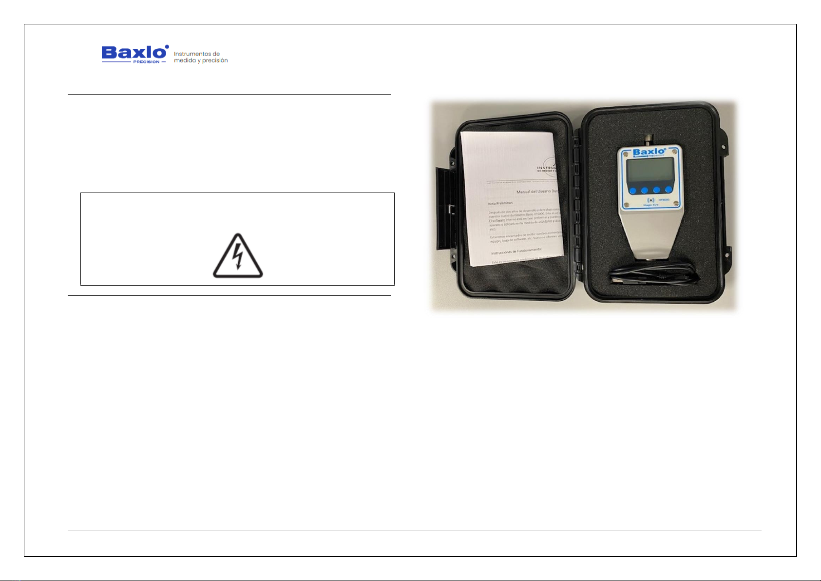
5. BOX CONTENTS.
•HT6000 Hardness Tester
•USB Cable
•Quick Start Guide
User Manual
HT6000 Digital Hardness Tester
We apologize for any inconvenience caused by minor inconsistencies in these instructions, which may occur as a result of device development and improvement. P a g e 7|26
6. GENERAL DESCRIPTION.
Thanks for purchasing our Baxlo Digital Hardness Tester. This device has
been carefully designed by applying our extensive knowledge in the field of
hardness measurement of different materials, taking advantage of the latest
available technology to offer a satisfactory and reliable use. This device is also
widely used to determine the degree of ripeness of all kinds of fruits and
vegetables. (Grapes, blueberries, tomatoes, strawberries, etc).
This manual describes the operation and the different functions of the
Baxlo HT6000 Digital Hardness Tester.
For the description of the functions of the device in this manual, the four
buttons on the front panel are numbered 1 to 4 from left to right.
6.1. FUNCTION.
The main purpose of this equipment is to determine the Shore hardness
of plastic materials, soft materials, fruits, etc.
The device works with a rechargeable battery via USB.
The device can store up to 5000 measures in the internal memory and
dump these data to the computer through the USB port.
6.2. WORKING PRINCIPLE.
The apparatus applies a force by means of an internal spring and reads
the penetration of an indenter of known dimensions into the material. The
penetration has a range of 0 to 2.5mm.
By accurately reading the penetration of the indenter into the material,
the apparatus gives a measure of the hardness of the sample from 0 to 100
shore units.
The penetration measurement is done by an on-chip magnetic sensor. It
has a backlit display to show the results and access the different configurations.
6.3. MAIN TECHNICAL SPECIFICATIONS
HT6000 DIGITAL HARDNESS TESTER
Brand
Baxlo
Model
HT6000
Dimensions
130 x 72 x 33mm
Weight
400 grams
Measuring Range
0-100 Shore Units
Resolution
0.1 Shore Units
Max. Measurement Error
0.5 Shore Units
Storage Capacity
5000 measures
Supply Voltage
5Vdc
Max. power consumption
2W
Battery capacity
2000mAh
Battery life
150 hours in Standby mode
IP rating
IP 54
Data communication
USB Cable

User Manual
HT6000 Digital Hardness Tester
We apologize for any inconvenience caused by minor inconsistencies in these instructions, which may occur as a result of device development and improvement. P a g e 8|26
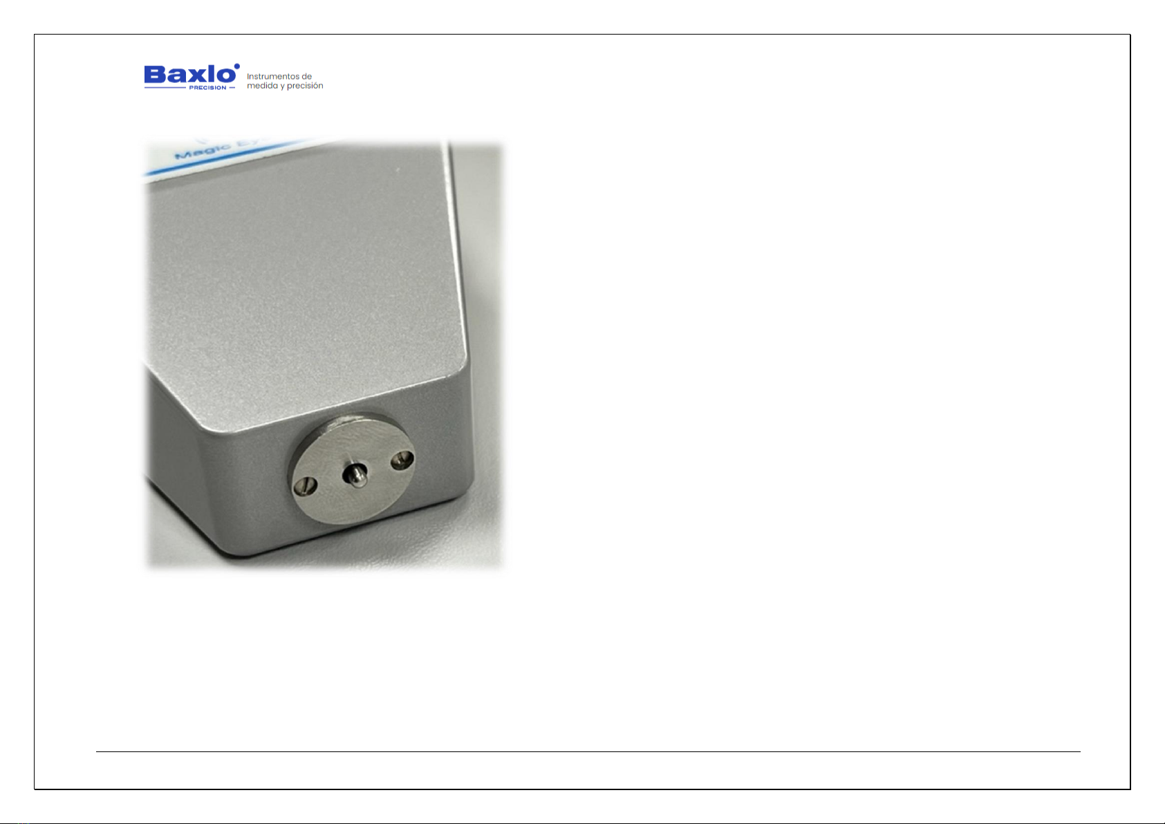
6.4. IMAGES.
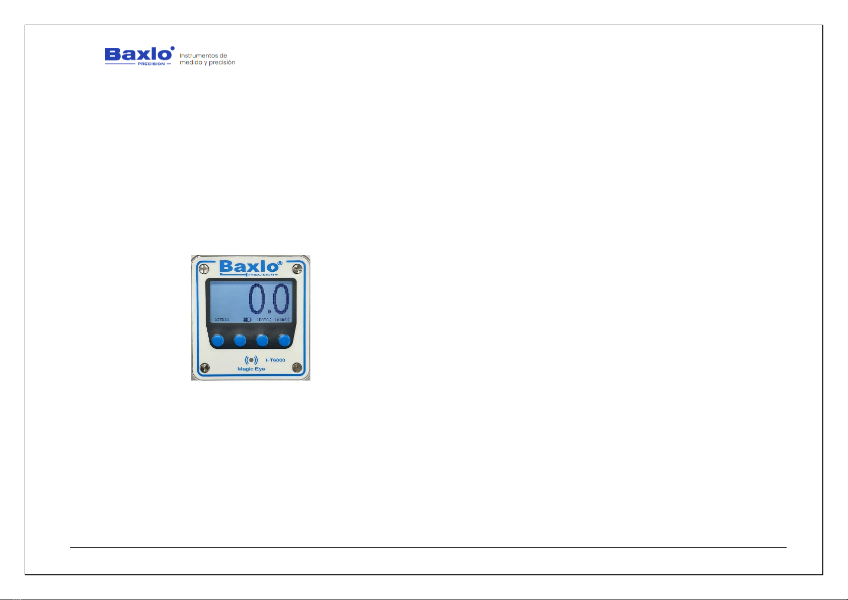
Main Unit
Detailed picture of the connections and the instrument clamping piece
User Manual
HT6000 Digital Hardness Tester
We apologize for any inconvenience caused by minor inconsistencies in these instructions, which may occur as a result of device development and improvement. P a g e 9|26
Detail image of the measurement sensor

User Manual
HT6000 Digital Hardness Tester
We apologize for any inconvenience caused by minor inconsistencies in these instructions, which may occur as a result of device development and improvement. P a g e 10|26
6.5. SWITCHING ON THE DEVICE.
To turn on the device, press the left button (1). If it does not turn on,
charge the device by connecting it using the attached cable to any USB socket.
A full charge will last from 4 to 6 hours.
6.6. SWITCHING OFF THE DEVICE.
With the device ON, press the key (1) for 3 seconds. The device will be
switched off and will only respond by pressing again the power button (1).
6.7. STANDBY MODE.
To save battery, the device enters the Sleep or Standby state after 1
minute of no activity (This time can be adjusted in the parameters section). If
the sensor is activated again or if any key is pressed, the instrument returns to
work normally. In the Standby state, the screen is simply turned off, but the rest
of the functions are still active.
6.8. CHARGING THE BATTERY.
When the battery indicator shows that it is discharged or the unit is off
and don’t respond to the pressing of any button, connect the device to any USB
socket by means of the supplied USB cable. The battery indicator will indicate
that it is charging. Disconnect from the USB socket, after 4 –6h.
6.9. MAIN FUNCTION OF THE BUTTONS.
•Button 1: On/Off the device. Resetting the measurement
•Button 2: Transfer the current reading via USB to the computer.
•Button 3: Measurement list / Data management
•Button 4: Settings
6.10. TAKING THE MEASUREMENTS.
Press the sample piece to be measured against the durometer disk
exactly the same as in a conventional analog durometer.
After X seconds (user-definable time) the device will emit a sound and
the “Magic Eye” LED will light up, showing the hardness of the piece. The “Magic
Eye” led will light up in blue, green or red depending on the margins that we
have entered in the configuration parameters.
•Blue = Over limit
•Green = Within limits
•Red = Below limit
The sound also indicates the state of hardness.
•Three beeps = Over limit
•Two beeps = Within limits
•1 beep = Below limit
At this point, the reading and all his associated data (date, time,
temperature, etc.) is stored in the internal memory of the device and
immediately afterwards, the device is ready for the next measurement.
The internal memory can store up to 5000 readings with all its associated
data.
6.11. TAKING MEASUREMENTS ON PLASTIC MATERIALS,
RUBBERS, PLASTERS, ETC.
1. Test probes must have a thickness of, at least 6 mm. and not
being subjected before to any mechanical effort. For thinner test

User Manual
HT6000 Digital Hardness Tester
We apologize for any inconvenience caused by minor inconsistencies in these instructions, which may occur as a result of device development and improvement. P a g e 11|26
blocks, you must provide a base of the same material or other of
the same hardness.
2. The surfaces to be tested must be as flat as possible. On rubber
materials they should be dusted with talcum powder prior to the
test.
3. Temperature is an important factor in hardness measurement.
Check that the ambient temperature indicated by the instrument
is within those specified by the measurement standards.
4. The standard stabilization time for elastic materials is 3 sec.
Check the stabilization time in the parameters section. The
stabilisation time is of utmost importance for the measurement
of the hardness of elastic materials.
5. Make at least three impressions at different positions on the test
piece, separated at least 5 mm from each other. To determine
the nominal hardness of the material, take the arithmetic mean
of the three measurements.
6. When testing, the durometer must exert a force of
approximately 1 kg on the surface to be measured. For the Shore
00 scale the force must be 250 g and for the Shore C, D and D0
scales the force shall be 5 kg.
7. The pressure must be exerted perpendicular to the surface. If
the shape and size of the workpiece allow, better results can be
obtained by using a device to hold the apparatus (durometer
stand) which allows the durometer to be pressed
perpendicularly, with an adequate and constant force.
6.12. TAKING MEASUREMENTS ON FRUITS.
1. The surface of the sample must be clean and dry. Choose an
area as smooth as possible.
2. Take at least two measurements on each side of the fruit. If you
obtain different readings, thake the average as a
representation of the hardness of the fruit.
3. When performing the test, the durometer should be pressed
firmly against the fruit sample with regular pressure while
assuring that the durometer´s lower disk is in contact with the
surface of the fruit. Please, make sure that the instrument axis
is as perpendicular as possible to the surface of the sample.
Once in position, exercise a pressure of approx. 1Kg except for
the F0 scale which is approx. 250 gr.
4. Wait without moving the piece until the stabilization time has
passed and the durometer beeps and fixes the reading on the
screen.
5. If the shape and size of the fruit allows it, better results can be
obtained by using a device to hold the apparatus (durometer
stand) which allows the durometer to be pressed
perpendicularly, with an adequate and constant force.
6.13. SUMMARY OF MENU OPTIONS.
Main menu
•Settings: Enter the configuration parameters submenu.
•Clear Memory Data: Deletes the list of measurements.
•Factory Settings: Returns the device to the factory default
options.

User Manual
HT6000 Digital Hardness Tester
We apologize for any inconvenience caused by minor inconsistencies in these instructions, which may occur as a result of device development and improvement. P a g e 12|26
•Clock Setup: Allows you to change the date and time.
•Date Format: Changes de date display between DD/MM/YY
(Day/Month/Year) and MM/DD/YY (Month/Day/Year)
•Exit: Return to the main screen.
Settings Menu
•Language: Change the language of the menus.
•Limit Hard: Upper limit of hardness. With greater measures the
Magic Eye led will flash blue and the measure is indicated with
three beeps.
•Limit Soft: Lower limit of hardness. With Lower measures the
Magic Eye led will flash red and the measure is indicated by one
beep. If a lower limit is programmed higher than the upper limit
by mistake, the lower limit will be automatically cancelled and
the device will only respond to the upper limit. The "Magic Eye"
LED will show in blue the measurements above the upper limit
and in red the measurements below it.
•Measurement Time: Defines the stabilization time that the
device takes to set the measurement. If a time = 0 is entered,
the display always shows the current value without stabilization
time. In this mode, the measurements are not stored nor does
the LED or the beep turn on.
•Free Mode: It is equivalent to put a Measurement time of 0 sec.
There is not a stabilization time. The display shows the current
hardness value but the measures are not stored and the beep
and magic Eye functions are not enabled.
Batcht: Allows you to enter the batch number. When uploading
the data to the computer, each measurement will be associated
with the batch number entered in this option.
Display: Allows you to switch between the full screen with all the
information and a summary screen with larger digits but less
information.
•TempDisplay: Change the temperature display between Celsius
and Farenheit degrees.
•Beep: Activates or deactivates the sound.
•ECOMode: Turns the “Backlight” illumination of the screen on /
off.
•Standby (sec): After this time without activity, the screen turns
off, but the device is still active.
•Exit: Return to the Main Menu.
6.14. DISPLAY DESCRIPTION
The device can show three screens which are described below.
•The main display has two modes which can be selected in the
parameter section.
oFull Display: Shows all the complete information
(Temperature, date, time, duration of the
measurement, etc.). We call this display mode Full
Mode.
oSimple display: Shows the current measurement with
larger digits but no additional information.
•Data management screen: Shows the complete List of
Measurements stored in the internal memory and also serves
to bulk that data to the computer.
User Manual
HT6000 Digital Hardness Tester
We apologize for any inconvenience caused by minor inconsistencies in these instructions, which may occur as a result of device development and improvement. P a g e 13|26
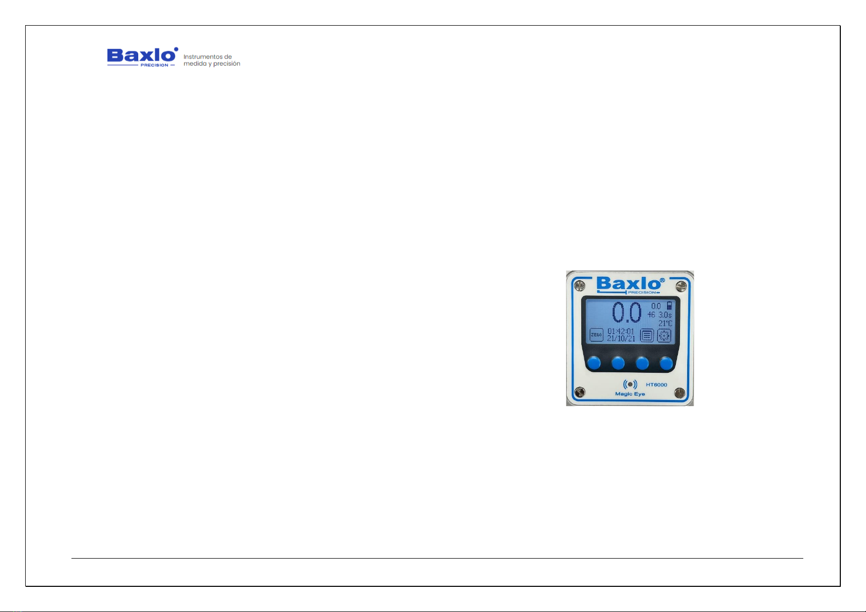
1. Main screen (Full mode).
The information provided by this screen is:
•Reading: Indicates the current hardness reading
•Maximum Reading: Indicates the maximum value reached by the
reading in the current measurement
•Measurement counter: Indicates the number of measurements made
since the last reset of the counter. It may not coincide with the order
number of the measurements on the data management screen. To
reset the measurement counter, press the Zero (1) and List (3)
buttons simultaneously.
•Battery Status Indicator: Indicates the battery charge status. When
the battery is being charged via the USB port the indicator will flash.
•Measurement Time: Indicates the time that the hardness
measurement will last. This value can be modified in the
configuration of the equipment settings. When the measurement is in
progress, it counts down and shows the time remaining to set the
hardness measurement. When the counter reaches zero, the
measurement is memorized and is displayed on the screen.
•Room temperature: Displays the room temperature in Celsius or
Fahrenheit degrees. (See parameters section to change the display
between Centigrade degrees and Fahrenheit degrees).
•Function Icons: Indicates the function of each button in the current
mode.
•Clock: Shows the current date and time.
The function of the buttons on this screen are:
•Zero Button (1): Resets the measurement indicator and corrects small
measurement errors in the rest position of the device.
•Data Communication Button (2): By pressing this button, the current
value of the measurement is sent through the communications port
along with all its associated data (measurement number,
temperature, date, time, etc.)
•Data Management Button (3): Pressing this button you enter the
measurement and data management list screen.
•Settings button (4): Enter the equipment settings configuration menu.
Image of the main screen
User Manual
HT6000 Digital Hardness Tester
We apologize for any inconvenience caused by minor inconsistencies in these instructions, which may occur as a result of device development and improvement. P a g e 14|26
2. Main screen (Simple mode).
The information provided by this screen is:
•Current reading: Indicates the current hardness reading
•Battery Indicator: Indicates the battery charge status. When the
battery is being charged via the USB port the indicator will flash.
•Buttons Function: Indicates the function of each button in the current
mode.
The function of the buttons is the same as in the Full mode screen.
Image of the main screen
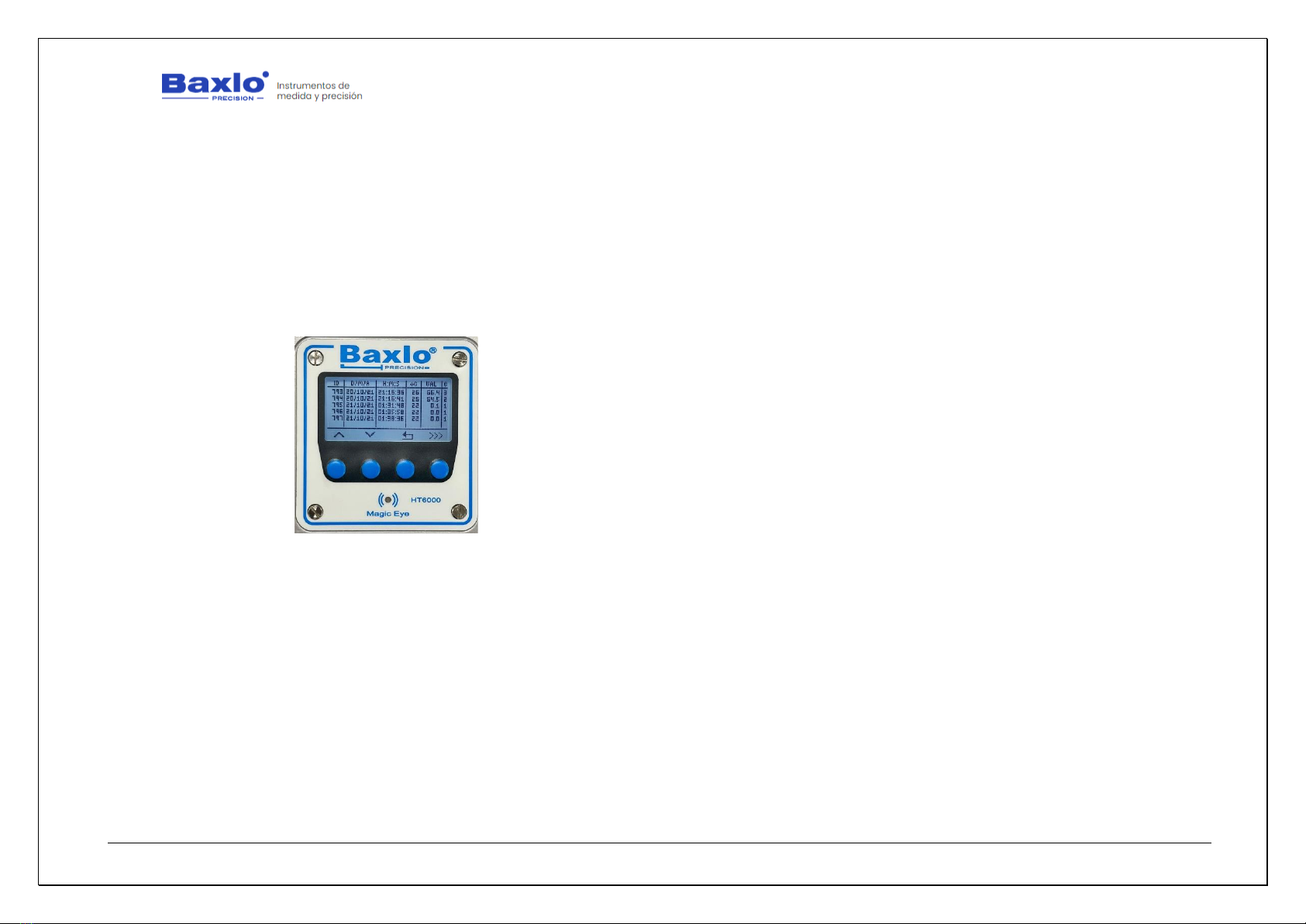
3. Data Management Screen.
Shows the complete list of the measurement history. The measurement
list can be cleared and reset from the main menu.
•Measurement number: Indicates the order number of the
measurement
•Date: Indicates the day on which the measurement was carried out in
DD/MM/YY format.
•Time: Indicates the time at which the measurement was made.
•Temperature: Indicates the room temperature in Celsius degrees.
•Reading: Indicates the hardness value.
•Category: Indicates the hardness category of the part according to the
following classification:
1. Below the hardness specified in the Soft Hardness parameter
2. Within the values specified between the Soft Hardness and
Firm Hardness parameters specified in the parameter menu.
3. Above the hardness specified in the Firm Hardness
parameter.
The functions displayed on this screen are:
•List Up: Scrolls the list of measurements up.
•List Down: Scrolls the list of measurements down.
•Exit: Returns to the main screen.
User Manual
HT6000 Digital Hardness Tester
We apologize for any inconvenience caused by minor inconsistencies in these instructions, which may occur as a result of device development and improvement. P a g e 15|26
•Data output: Pressing this key for more than two seconds starts the
block communication of all the measurements, with their associated
data, to the computer connected to the USB port. This communication
may take a while depending on the volume of data to be transferred.
During the time the communication lasts, the Magic Eye LED will flash
green. Once all the data has been communicated, the led will stop
flashing and normal operation can be continued.
Image of the data management screen
User Manual
HT6000 Digital Hardness Tester
We apologize for any inconvenience caused by minor inconsistencies in these instructions, which may occur as a result of device development and improvement. P a g e 16|26
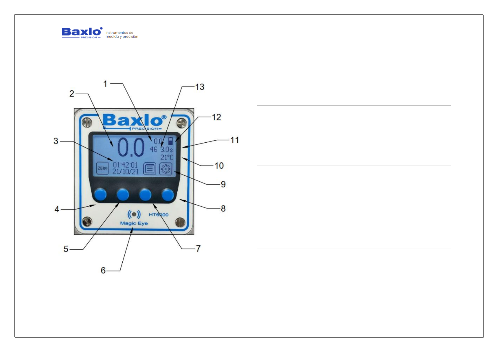
4. Explanatory images of the screens.
Image of the main screen
1
MAXIMUM READING
2
READING
3
CLOCK: TIME / DATE
4
RESET BUTTON
5
DATA SEND BUTTON
6
LED MAGIC EYES
7
DATA MANAGEMENT BUTTON
8
SETTINGS BUTTON
9
FUNCTION ICONS
10
ROOM TEMPERATURE
11
MEASUREMENT TIME
12
BATTERY STATUS INDICATOR
13
MEASUREMENT COUNTER

User Manual
HT6000 Digital Hardness Tester
We apologize for any inconvenience caused by minor inconsistencies in these instructions, which may occur as a result of device development and improvement. P a g e 17|26
Image of the main screen
1
CURRENT READING
2
BATTERY INDICATOR
3
BUTTON FUNCTION
4
RESET BUTTON
5
DATA SEND BUTTON
6
DATA MANAGEMENT BUTTON
7
SETTINGS BUTTON
User Manual
HT6000 Digital Hardness Tester
We apologize for any inconvenience caused by minor inconsistencies in these instructions, which may occur as a result of device development and improvement. P a g e 18|26
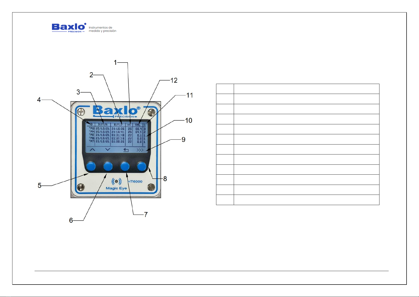
Image of the data management screen
1
TEMPERATURE
2
TIME
3
DATE
4
MEASUREMENT NO.
5
LIST UP
6
LIST DOWN
7
EXIT BUTTON
8
BULK DATA COMMUNICATION
9
FUNCTION ICONS
10
LIST OF MEASURES
11
CATEGORY
12
READING

User Manual
HT6000 Digital Hardness Tester
We apologize for any inconvenience caused by minor inconsistencies in these instructions, which may occur as a result of device development and improvement. P a g e 19|26
6.15. DATA EXPORT TO EXCEL.
The following steps explain how to export the data contained in the
device's memory to an Excel table.
What do we need?
We will need the following:
•Baxlo Digital Durometer
•USB Cable
•Windows 10 or 11 computer with Excel installed.
•USB communication drivers.
•The Termite Communications Program.
•Excel data template.
Step by step instructions:
1. Installation of communication drivers:
i. Unzip the file "Durometer Drivers Baxlo.Zip" that we
have previously provided.
ii. Run the installer:
Inside the “Baxlo Durometer Drivers” folder there are
2 executable files (Files with the .exe extension).
For computers with Windows 10 or Windows 11 64-
bit, you must run the file
"CP210xVCPInstaller_x64.exe" and follow the
installation instructions.
iii. Connect the durometer using the supplied USB cable.
iv. Once the installer has been executed, and the
durometer is connected to the computer, we are
going to verify that the driver has been successfully
installed using the Windows Device Manager. To do
this, in the Windows search bar we will enter the
following command: “devmgmt.msc”.
v. The following screen will appear:
We will locate the lines marked in the previous figure that indicate that
the Durometer is connected and has been recognized.
Table of contents
Popular Test Equipment manuals by other brands


Pace
Pace ThermoTweez Handpiece TT-65 Operation & maintenance instructions

PCB Piezotronics
PCB Piezotronics 482C26 Installation and operating manual

Rohde & Schwarz
Rohde & Schwarz RTE Series Getting started

REED
REED R5500 instruction manual

Bayrol
Bayrol 287300 instruction manual

EXFO
EXFO FTB-8500 Series user guide

Klein Tools
Klein Tools LAN EXPLORER instructions

Textron
Textron Tempo PE930 instruction manual

Wiltron
Wiltron 59A50 Operation and maintenance manual

ENDEVCO
ENDEVCO 123 instruction manual

Standard Electric Works
Standard Electric Works 6500 LC instruction manual

yellow jacket
yellow jacket YJ-LTE 95730 Operation and maintenance manual