ISA T2000 User manual

DATE: 20/04/2011
DOC.MIE12110 REV.4
T2000
INTRODUCTORY GUIDE

DOC. MI
E12210 Rev.
4
Page
2
of
86
REVISIONS SUMMARY VISA
NPAGE DATE
1All 25/04/2006 Issued Lodi.
239 to 43 8/06/2006 Added the
Calibration
chapter
Lodi
3All 23/11/2009 Minor corrections Lodi
471, 72 20/4/2011 Modified for the
firmware revision
1.40
Lodi

DOC. MI
E12210 Rev.
4
Page
3
of
86
SHORT FOREWORD.......................................................................................................5
INTRODUCTION................................................................................................................6
1 TEST SET DESCRIPTION AND USE...................................................................9
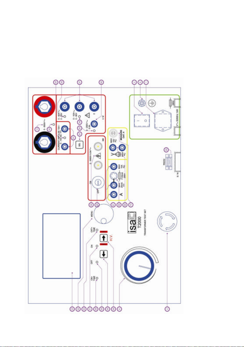
1.1 THE FRONT PANEL....................................................................................................9
1.2 THE POP-UP MENU.................................................................................................12
1.2.1 Transformers selection....................................................................13
1.3 POWER-ON...............................................................................................................18
1.4 OUTPUTS DESCRIPTION AND HAZARDOUS SITUATIONS .........................20
1.4.1 Main current and voltage outputs............................................20
1.4.2 HV voltage output................................................................................22
1.4.3 Hazardous situation summary...................................................23
1.5 CURRENT GENERATION.........................................................................................24
1.6 OPTIONAL THERMAL PRINTER.............................................................................26
1.7 PROTECTIONS .........................................................................................................26
2 TRANSFORMERS TESTING FUNDAMENTALS...........................................30
2.1 CURRENT TRANSFORMERS...................................................................................30
2.2 REMANENCE..............................................................................................................31
2.3 HIGH CURRENT TESTS..........................................................................................31
2.4WINDING RESISTANCE TEST.............................................................................31
3 WHAT’S INSIDE?.......................................................................................................33
3.1 PHYSICAL DESCRIPTION.....................................................................................33
3.2 DETAILED FUNCTION DESCRIPTION................................................................37
3.2.1 Main output transformer, XTF10350 (5).............................37
3.2.2 Main front board PWA11411 (17).............................................38
3.2.3 TRANSFORMERS board PWA21412 (83)...............................38
3.2.4 CONV-T 3000 board PWA21401 (16).....................................39
3.2.5 INTE ON-OFF T 3000 board PWA11410 (7)........................40
3.2.6 MICR T1000 board PWA41300 (15)........................................40
4 THE HELL, IT DOESN’T WORK..........................................................................42
4.1 INTRODUCTION.......................................................................................................42
4.2 ERROR MESSAGES.................................................................................................42
4.3 TROUBLE SHOOTING.............................................................................................46
4.4 AT POWER-ON DOES NOT TURN ON.................................................................47
4.5 NO OUTPUT FROM THE MAIN CURRENT AND VOLTAGE..............................48
4.6 THE AC VOLTAGE MEASUREMENT IS NOT STABLE......................................48
4.7 PROBLEMS DURING UPGRADE............................................................................48
4.8 FALSE ALARM OF MISSING GROUND CONNECTION....................................49

DOC. MI
E12210 Rev.
4
Page
4
of
86
4.9 THE DISPLAY BACKLIGHT DOES NOT TURN ON OR THE DISPLAY
DOES NOT OPERATE.......................................................................................................49
4.10 A110 VRATED TEST SET WAS POWERED AT 220 V.............................51
4.11 THE TEST SET DOES NOT COMMUNICATE WITH THE PC........................53
4.12 FAULT ON THE 10 VOR 600 VEXTERNAL MEASUREMENT....................55
4.13 FAULT ON THE 10 AEXTERNAL MEASUREMENT.........................................65
4.14 FAULT ON THE REAL TIME CLOCK..................................................................69
4.15 THE ENCODER IS BROKEN................................................................................70
4.16 UPGRADE TO FIRMWARE REVISION 1.40....................................................71
4.17 THE FAULT CANNOT BE FIXED.........................................................................73
5 CALIBRATION.............................................................................................................77
5.1 INTRODUCTION......................................................................................................77
5.2 CALIBRATION PROCEDURE................................................................................77
5.3 T2000 OUTPUT CALIBRATION........................................................................79
5.3.1 OUTPUT CURRENTS CALIBRATION.............................................79
5.3.2 OUTPUT VOLTAGES CALIBRATION..............................................80
5.4 EXTERNAL INPUT CURRENTS........................................................................82
5.5 EXTERNAL INPUT VOLTAGES........................................................................84
APPENDIX 1 SPARE PARTS LIST.........................................................................86

DOC. MI
E12210 Rev.
4
Page
5
of
86
SHORT FOREWORD
Dear T 2000 user,
I often wondered why the user’s manual is not very much used,
even if it includes valuable information. As me too I am a user of
such manuals, the answer I have given myself is that valuable
information are concealed somewhere in the thick thing, and I do
not have time to waste to find it. So, either the manual is actually
of help, or I ignore it.
This is why I decided to split the T 2000 manual in three:
specification, with all performance details; application manual, with
instructions about how to use it one its operation is understood;
introductory guide, with the device description and basic
information. The idea is that you may read once the device
description, while you need application examples more than once;
so, why not to split the manual in three?
The only exception to this organization is next page: it reminds to
be cautious when using these test sets. We are on the field since
more than 50 years, and no injury has ever been reported; yet,
your kids want you back home after work.
Have a good work with T 2000!
Primo Lodi
Q&A Manager

DOC. MI
E12210 Rev.
4
Page
6
of
86
INTRODUCTION
T 2000 allows performing all the test to be performed on current
and voltage transformers. The following table lists the tests that
can be performed on CT and VT.
N. TEST
OF TEST DESCRIPTION
1CT Ratio, Voltage mode
2CT Ratio, polarity and burden
3CT Burden; secondary side
4CT Excitation curve
5CT Winding or burden resistance
6CT Voltage withstand
7CT Polarity by impulses
8VT Ratio; polarity
9VT Burden, secondary side
10 VT Ratio, electronic transformers
11 VT Voltage withstand
12 VT Secondary over-current protection
13 PT Ratio per TAP
14 PT
Resistance of Tap Changer
contacts
15 PT
Tap Changer dynamic resistance
test
16 RGround resistance and resistivity
With external options, T 2000 can test:
. With the High IDC module, up to 400 A: contact resistances, in
the micro-Ohm range;
. With the high current booster: primary tests, up to 2000 A;
. With the very high current booster: primary tests, up to 4000 A.
The basic T 2000 function is to generate current and voltages, as
requested by the type of test to be performed, that is selected on
the LCD screen by means of the multi-function knob. Test results
are kept in memory, and can be transferred to a PC at a later
time, along with settings.

DOC. MI
E12210 Rev.
4
Page
7
of
86
The instrument contains one generator with many outputs: High
AC current; Low AC current; Low DC current; Current impulses;
High AC voltage; Low AC voltage; Low DC voltage.
All outputs are adjustable and metered on the large, graphic LCD
display. With the multi-purpose knob and the LCD display it is
possible to enter the MENU mode, that allows to set many
functions, that make T 2000 a very powerful testing device, with
manual and semi-automatic testing capabilities, and with the
possibility to transfer test results to a PC via the RS232 interface.
These results can be recorded, displayed and analysed by the
powerful TDMS software, which allows creating a data base of
test results for all the plant.
The ease of operation has been the first goal of T 2000: this is
why the LCD is graphic, and so large. With it, the dialogue in MENU
mode is made easy. Besides, all T 2000 outputs relevant to the
selected test are continuously measured, and output values are
displayed, with no extra effort to the operator.
Additional features are:
. Two meters, current and voltage, with independent inputs, and
with High and Low inputs each, allow measuring CT or VT outputs
or any other source;
. The optional thermal printer gives the immediate printout of the
CT saturation curve;
. An auxiliary contact, that follows START and STOP inputs, allows
simulating the circuit breaker.
At power-on, there is a message asking to wait for the self
diagnosis is completed. After this, the following menu is displayed.

DOC. MI
E12210 Rev.
4
Page
8
of
86
The desired operation is accessed by the multi-function wheel.
The following chapters explain how to operate with the above
selections.
NOTE: WINDOWS is a trademark of MICROSOFT inc.

DOC. MI
E12210 Rev.
4
Page
9
of
86
1 TEST SET DESCRIPTION AND USE
In this chapter we describe the test set and inform about the
operations that are common to relay or transformers testing.
1.1 THE FRONT PANEL

DOC. MI
E12210 Rev.
4
Page
10
of
86
The following list includes the key components inside T 2000.
1) Supply socket and main supply fuse, rated T5A, incorporated in
the supply socket.
2) Power-on switch, with light.
4) Emergency push-button with lock-in.
5) Main outputs transformer.
6) Main outputs adjustment.
7) INTE ON-OFF printed circuit board; code YWA11410.
8) Earth socket.
11) Back panel board ; code YWA11413.
12) High output current measurement transformer.
13) Output sockets for high current output.
15) Microprocessor board, code YWA41300.
16) Converter board code YWA11401.
17) Front panel board; code YWA11411.
22) MENU control knob, with switch.
23) Display.
25) Serial interface connector.
26) Main current outputs measuring transformer.
27) Main current output sockets.
28) High Voltage enable key.
29) Variable transformer home position switch.
44) 800 A range selection light.
45) 40 A or 25 V range selection light.
46) 10 A or 90 V range selection light.
49) ON + TIME light: current is generated and time metered until
STOP is detected.
50) OFF light: no current generation.
51) ON light: current is generated.
52) OFF + TIME light: current is removed and time metered until
STOP is detected.
53) Main AC voltage selection light.
54) Main DC current or current impulses selection light.
55 and 56) START and STOP push-buttons.
57) Push-button for the selection of main output.
58) HV voltage on light.
60) Main AC voltage safety sockets.
61) Main DC current or current impulses safety sockets.
67) External current meter safety sockets.

DOC. MI
E12210 Rev.
4
Page
11
of
86
68) External voltage meter safety sockets.
69) 25 mA metering input protection fuse.
70) 10 V measurement input connector.
80) Transformer protection thermal switches.
81) Serial interface supply transformer.
82) Electronic power switch (SCR).
83) TRANFORMERS board for the auxiliary supplies, PWA11412.
84) HV output measurement transformer.
85) Fan.
86) Primary circuit breaker.
87) HV opening relay.
88) HV output current meter.
89) Input current meter.
NOTE: the connector to the 10 V input (70) can be removed only
acting on the connector body. DON’T PULL THE CABLE, AS YOU
COULD DAMAGE IT!

DOC. MI
E12210 Rev.
4
Page
12
of
86
1.2 THE POP-UP MENU
The following is the list of features that are menu selected. The
menu is operated by means of the control knob marked MENU, that
incorporates a switch. The menu is entered pressing the knob and
selecting the item moving the knob. Once the item has bee found
and programmed, pressing the arrow the menu moves back of one
step, so that other programming can be performed; else, selecting
ESC the menu returns to the main window.
The first display is the following.
Next screens depend upon the type of selection:
. For transformer tests, there is a dedicated screen for each type
of test: only relevant parameters are displayed and recorded.
. Other selections: Resistance, Results, Preferences, Test header.
Any setting can be saved to and recalled from the memory. Up to
10 settings can be stored and recalled; setting no. 0 is the default
one, and pops up at power-on. Settings are permanently stored in
the memory; new settings can be written to the same address
after confirmation. For normal mode operation it is possible to
recall the standard setting, that cannot be modified.
During the test, test results can be stored in the memory (up to
500 results may be stored). At the end of test, settings and test
results can be transmitted to a PC provided with TDMS. The
software allows saving test results, examining them and so on.
The specification of TDMS is given in a separate document.

DOC. MI
E12210 Rev.
4
Page
13
of
86
When the PC is connected, settings can also be created and
transferred into T 2000 using TDMS.
1.2.1 Transformers selection
With this selection, the choice is: CT; VT; PT. After entering the
final selection, the operator can input the relevant parameters,
still by using the multi-function knob: turning it allows changing
the parameter; pressing it makes it possible to go to next
parameter.
Once all parameters are set, it is possible to start the test and
execute it. Test time is kept to the minimum to avoid the excess
of heating.
The following table summarizes all tests and the corresponding
performances.

DOC. MI
E12210 Rev.
4
Page
14
of
86
TES
T
OF
TEST
DESCRIPTIO
N
INPUT
DATA CONN.
OUT CONN.
IN MEASUREMENTS
CT
N. 1 Ratio Voltage
mode -I
primary
;
-I
second
ary
(nomin
al
values)
-
Voltag
e
output
-
Voltag
e input
High/Lo
w V AC
to CT
seconda
ry
CT
primary
to low
or high
Vin
1) High / Low VAC
out;
2) Low V in;
3) Polarity;
4) Actual ratio;
5) Ratio error %;
and excitation
curve, if selected
CT
N. 2 Ratio, polarity
and burden -I
primary
;
-I
second
ary
(nomin
al
values)
;
-
Clamp
Y/N;
-
Clamp
ratio;
-
Voltag
e
input.
High I
AC
to CT
primary
CT
second
ary
to high
I in;
(Low
Iin with
Clamp)
;
CT
second
ary to
Vin low
or high.
1) High I AC out
(primary);
2) I in
(secondary);
3) Nominal ratio;
4) Actual ratio;
5) Ratio % error;
6) Polarity
7) VA rating
8) Power factor;
CT
N. 3 Burden,
secondary side
-IN
second
ary
(nomin
al
value);
-
Voltag
Low I AC
to
CT
burden
CT
burden
to Vin
1) I out
(secondary);
2) V out
(secondary);
3) Phase V-I out
(secondary);
4) Power factor;
5) VA rating;

DOC. MI
E12210 Rev.
4
Page
15
of
86
e
input.
-
Curren
t
output
CT
N. 4 Excitation
curve -
Voltag
e
output
-I nom
second
ary
-VA
rating
-
Accurac
y class
-
Overlo
ad
-
Interna
l loss
-
Standa
rd
(IEC,
ANSI)
High V
AC to CT
seconda
ry
1) High V AC out;
2) I out of High V
AC;
3) Iout-Vout
curve;
4) Current at
knee, IKm;
5) Voltage at
knee, VKm
CT
N. 5 Winding or
burden
resistance
-
Temper
ature
compe
nsation
Y/N
-
Ambien
t and
target
temper
atures
Low I DC
to CT
burden
or
winding
CT
burden
to Vin
1) Low I DC out;
2) V of lowI DC
out;
3) Resistance;
4) Compensated
resistance
CT
N. 6 Voltage
withstand -Max
High V
AC ;
-Max I
test
-Tmax
High V
AC to:
Primary
and
seconda
ry;
1) High V AC out;
2) I out of High V
AC ;
3) Elapsed Time

DOC. MI
E12210 Rev.
4
Page
16
of
86
CT
N. 7 Polarity by
impulses Low IDC
to CT
primary
CT sec.
to Iin 1) I DC out;
2) I secondary;
3) Polarity
TEST
OF TEST
DESCRIPTION
INPUT
DATA CONN.
OUT CONN. IN
MEASUREMENTS
VT
N. 8 Ratio; polarity V
primary
in kV;
V
seconda
ry;
Connecti
on LL,
LN for
primary
and
seconda
ry
(nominal
values)
High V
AC
to VT
primary
VT
secondary
to V in
1) High VAC
(primary)
2) V in
(secondary);
3) Phase shift ;
4) Actual ratio;
5) Ratio error %;
6) Polarity
VT
N. 9 Burden,
secondary side
-V
seconda
ry
(nominal
value)
-
Connecti
on LL,
LN
-
Voltage
output
-
Voltage
input
Low V
AC to
VT
burden
VT burden
to V in (if
enabled)
1) V out
(secondary);
2) I out
(secondary);
3) Phase V-I;
4) Power factor;
5) VA rating
VT
N. 10
Electronic
Voltage
Transformers
-V
primary;
-V
seconda
ry;
-
Connecti
on LL,
High V
AC
to VT
primary
VT
secondary
to V in
1) High VAC
(primary)
2) V in
(secondary);
3) Actual ratio;
4) Ratio error %;
5) Polarity

DOC. MI
E12210 Rev.
4
Page
17
of
86
LN for
primary
and
seconda
ry
(nominal
values)
VT
N. 11
Voltage
withstand -Max
High V
AC;
-Max I
test;
-Test
duration
.
High V
AC to
Primary
and
second
ary;
1) High V AC out;
2) I out of High V
AC ;
3) Elapsed Time
VT
N. 12
Over-current
protection -I Trip
-Output
current
Low I
AC to
VT
protecti
on
1) I out
(secondary)
2) I trip
PT
N. 13
Ratio per Tap -V
primary
in kV;
-V
seconda
ry;
-
Connecti
on LL,
LN for
primary
and
seconda
ry
High V
AC
to VT
primary
VT
secondary
to V in
1) High V AC out;
2) I of High V AC;
3) Phase V-I
4) V in;
5) Actual ratio;
6) Ratio error %.
PT
N. 14
Resistance of
Tap Changer
contacts
-
Tempera
ture
compens
ation
Y/N
-
Ambient
and
target
tempera
tures
Low I
DC V in 1) I DC out;
2) V of IDC out;
3) Resistance;
4)Compensated
resistance
PT
N. 15
Dynamic tap
changer test -Time
base Low I
DC V in 1) I DC out;
2) V of IDC out;

DOC. MI
E12210 Rev.
4
Page
18
of
86
-trigger
level 3) Resistance;
4) Resistance
waveform
R
Grid
N. 16
Resistance or
resistivity of
earthing grid
-Output
voltage
-Input
voltage
Low V
AC to
auxiliar
y spike
V input
from
measurem
ent
spike(s)
1) Output
voltage
2) Output current
3) Input voltage
4) Ground
resistance or
Ground resistivity
1.3 POWER-ON
At first, be sure that the main control knob (6) is turned (rotated)
to the zero position (complete counter-clockwise). The reason is
that the current generator is actually a high current voltage
generator. If the output is connected to the load (typically low
impedance), as soon as the test is started, a very high current
can circulate in the circuit.
Next, connect the mains supply cable to the instrument and then
to the supply. The power supply must be made of three wires:
phase, neutral and ground. It is also intended that the neutral will
have a low voltage with respect to ground (20 V maximum).
If you need an extension cable, use a cable where the copper
cross section of 6 sq. mm. minimum: this serves to prevent
heating and voltage drops, that would cause also a reduction of
the performances.
Power-on T 2000: the test set checks if it is connected to the
ground; if not, it alerts the operator with the following message.
All operations will be inhibited until the ground is available; power-
off, connect to the ground and then power-on again. Usually the
grounding connection is provided by the power supply cord; if the
ground connection is not available at the power outlet, connect T
2000 to ground using the yellow/green cable with crocodile

DOC. MI
E12210 Rev.
4
Page
19
of
86
provided. The connection to water pipes or to a big metal frame
will do.
NOTE: this protection checks the voltage between phases and
ground; at least one of them (the neutral) must have a low
voltage with respect to the ground. This means that T 2000
cannot be powered by two phases of a 220 V (or 110 V) three-
phase supply (127 V or 63.5 V phase to neutral).
If you are in this situation, and you are sure that the ground is
there, you can over-ride the alarm as follows:
. Press the > key;
. The alarm will show up again;
. Press the > key four times in all: the message will disappear, and
you can continue.
T 2000 diagnostic tests also the voltage supply value: if it
exceeds the limits of ± 20%, one of the following messages will be
displayed.
If the ground is connected, the following message is displayed.
During this time, a diagnostic sequence controls:
. Key microprocessor board components;
. Auxiliary supply voltages.
If something is wrong, the operator is alerted by one of the
following messages.

DOC. MI
E12210 Rev.
4
Page
20
of
86
At the end of it, default selections are active; T 2000 is in the
OFF state.
If some selection keys are pressed at power-on, the following
message warns the operator to release them.
After power-on, the following control lights turn on (default
situation):
. TEST OFF (50);
. MENU SELECTION: 40 A SOCKET (45).
To operate the test set it is necessary to perform the pop-up
menu selections. During operation, if something goes wrong the
test set protections intervene; usually, the operator is alerted by
a message.
1.4 OUTPUTS DESCRIPTION AND HAZARDOUS SITUATIONS
1.4.1 Main current and voltage outputs
The first thing to be understood is that all main outputs are
generated by a sole transformer, and are adjusted by knob (6); as
a consequence:
. It is impossible to adjust separately the AC current and the AC
voltage;
.The output selection does not open the unselected outputs;
. Only one connection should be made to main outputs. In
particular, if there are two connections to output sockets (27)
and (13), the displayed current value is meaningless, currents will
divide as a function of the burden.
The situation of zeros is the following:
. There are three independent zero: 800 A; 3000 V; all other main
outputs;
. The zero of low current outputs is in common with the 250 V AC
output, but it is not directly connected to the zero of the DC
current output, as there is a rectifying bridge between them. DO
NOT CONNECT THESE ZERO BETWEEN THEM: this would cause a
short-circuit on one of the rectifying diodes.
Other manuals for T2000
2
This manual suits for next models
1
Table of contents
Other ISA Test Equipment manuals
Popular Test Equipment manuals by other brands

Kenwood
Kenwood CS-5230 Service manual

Good Will
Good Will MDO-2000E Series user manual

Dräger
Dräger Interlock 7500 Instructions for use

RKI
RKI GX-2003 user guide

PAS Systems International
PAS Systems International PAS Vr. Alcohol Screening & Verification... instruction manual

UE Systems
UE Systems ULTRAPROBE 10000 instructions