ENDEVCO 123 User manual

Endevco Model 123
3-Channel
PE/IEPE Signal Conditioner
INSTRUCTION
MANUAL
IM123
Revision A2
October 28, 2013

2
Safety............................................................................................................................. 3
Description..................................................................................................................
... 4
Wiring Information.................................................
......................................................... 5
Front
Panel..................................................................................................................... 6
Rear
Panel..................................................................................................................... 7
Setting Up the Model
123............................................................................................... 8
Calculating/Setting Gain
………………………………………………………………….… 8
Filter Mo
dule Installation………………………………………………………………….... 10
Signal Ground/Power Ground
Isolation…………………………………………………… 11
Included/Optional
Accessories……………………………………………………………... 11
Outline Dimensions..................................................................
.......................................12
Table of Contents
3
Safety
Read this manual in its entirety before operating the Model 123 Signal Conditioner. Read all wiring and power
hookup instructions and understand the requirements prior to using another m
anufacturer's products with the
Model 123
. Insure that any product being interfaced with the Model 123 is wired according to prevailing local
safety and operational standards before operating.
The following symbols and terms may be found on the Model 123 and its manuals and indicate important
information.
When found on the device, this symbol indicates that the operator should refer to the manual for
important instructions on the proper use of this device. When found in the manual, this symbol
indicates that the reader should understand the implications contained in the text before operating
the device.
This symbol indicates that a shock hazard may be present. Read the instruction manual carefully
and insure that the device is wired properly and that all settings have been checked prior to applying
power to the device.
The WARNING label indicates important information that should be heeded for safe and proper performance
of the device.
The
CAUTION label is used to indicate that damage to the power supply or equipment connected to it could
occur if directions are not followed. Warranty could be invalidated if the instructions in this manual are not
followed.
Disassembling the Instrument
Turn Input Power Switch OFF before removing power cable from the instrument.
Remove power cable from instrument before disassembling any part of the instrument.
Grounding
To avoid electrical shock, the power cord protective grounding conductor must be
connected to power ground.
Fuse Replacement
For continued fire protection, replace fuse only with the specific type and rating by
qualified personnel (Reference Manual "Rear Panel" section). Disconnect the power
cord before replacing fuse.

4
Description
The Model 123 is a new microprocessor controlled 3-Channel Signal Conditioner for Piezoelectric (PE) or
Integrated Electronic Piezoelectric (IEPE) sensors. The Model 123 incorporates a charge amplifier when
used with PE sensors. An integral 0, 4, or 10mA, user selectable, current source with 20Vdc compliance
voltage is utilized with IEPE sensors. A user friendly interface allows programming Input Sensitivity and
Output Sensitivity, then allowing the instrument to calculate the amplifier gain. All gain selections are
stored in non-volatile memory and reinitialized when power is applied. Gain can also be entered directly
if desired.
The Model 123 utilizes a microprocessor SLEEP mode to eliminate high frequency clock noise and their
associated harmonics. The microprocessor WAKES momentarily to acknowledge front panel switch
depressions, then goes to SLEEP immediately after processing and executing the requested function.
This allows the amplifiers to operate with minimum self generated noise and provides clean, clock free
amplified signals. The Model 123 also uses low noise linear voltage regulators instead of switching
regulators to minimize interference.
The Model 123 uses 12 bit DACs, for each channel, to set amplifier gains from 0.00 to 999.9 with 0.5%
precision. Amplifier gains can be changed “on the fly” without damage to the instrument.
The Model 123 provides 1.5Hz to 230 kHz broadband frequency response, with optional plug-in, 4-pole
Butterworth high pass and low pass filter modules available. Filter selection is provided via rear panel
switches. Front panel LEDs display filter selections. Each channel can drive 10mA into a 1k ohm load.
The Model 123 channel-to-channel signal ground is non-isolated. However, signal ground is isolated
from power ground. An internal DIP switch allows shorting signal ground to power ground.
A rear panel voltage selector switch allows selection of 100, 115 or 230 Vac, 50-60Hz, input power.
The Model 123 is designed for CE compliance for EMC emissions and immunity and for Product Safety.
The Model 123 is directly compatible with Endevco’s line of PE and IEPE transducers.
Wiring Information
5
CH1, CH2 and CH3 Signal Inputs
Reference the rear panel drawing shown on page 7.
Before connecting power to the instrument, verify INPUT POWER (ON/OFF) switch is in the OFF position
and the INPUT POWER SELECT switch is set to the correct voltage. Connect inputs and outputs prior
to applying power to the instrument.
For connection to PE sensors set INPUT SELECT switch to PE position and connect to the BNC input for
PE sensors.
For connection to IEPE sensors set INPUT SELECT switch to IEPE position and connect to the BNC
input for IEPE sensors. Select 4mA or 10mA source current for IEPE sensor excitation.
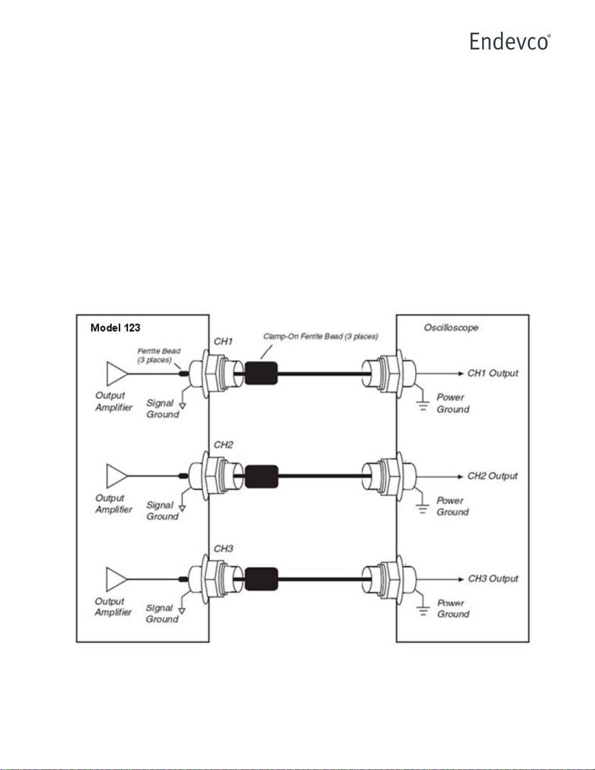
CH1, CH2 and CH3 Signal Outputs
Typical Hookup to an Oscilloscope

6
Front Panel

7
Rear Panel

8
Setting up the Model 123
Verify the POWER ON/OFF switch is in the OFF position and the POWER INPUT SELECTOR SWITCH
is set to the proper input power voltage prior to making any input or output connections to the instrument.
1. Connect sensor to its proper inputs (PE/IEPE).
2. Connect outputs.
3. Disable the High Pass (HP) and Low Pass (LP) filters by selecting HP OUT and LP OUT on the
rear panel.
4. Set the appropriate input type (PE/IEPE) on the rear panel.
5. If using IEPE sensors, set the appropriate IEPE current source value.
6. Connect AC power to the instrument.
7. Turn POWER ON/OFF switch ON.
8. Verify the following on the front panel.
a. POWER LED illuminates.
b. The appropriate PE or IEPE LEDS illuminate.
c. HP and LP filter LEDs are OFF.
Calculating/Setting Gain
1. To allow the instrument to calculate the gain for CH1, perform the following.
a. Set the SENSITIVITY/GAIN (SW1) thumbwheel switch to the transducer sensitivity.
Example: If the PE or IEPE transducer has a sensitivity of 10.52 pC/g or mV/g, set
the SENSITIVITY/GAIN thumbwheel switch to 0010.52.
b. Depress CH1 (SW5) switch momentarily. The CH1 LED will illuminate.
c. Depress ENTER (SW2) switch for INPUT SENSITIVITY. The instrument will store the
INPUT SENSITIVITY value for CH1 in non-volatile memory for use in calculating the gain
setting. The CH1 LED will extinguish.
d. Set the SENSITIVITY/GAIN (SW1) thumbwheel switch for the desired output sensitivity.
Example: If an OUTPUT SENSITIVITY of 100mV/g is desired, set the
SENSITIVITY/GAIN switch to 0100.0.
e. Depress CH1 (SW5) switch momentarily. The CH1 LED will illuminate.
f.Depress ENTER (SW3) switch for OUTPUT SENSITIVITY. The instrument will store the
OUTPUT SENSITIVITY value for CH1 in non-volatile memory for use in calculating the
gain setting. The CH1 LED will extinguish.
Note: The INPUT SENSITIVITY and OUTPUT SENSITIVITY for CH1 is entered and set.
The instrument is now ready to calculate CH1’s gain based on these settings. If these
values are not updated, they will continue to be used whenever the instrument is asked to
calculate CH1’s gain.

9
g. Depress CH1 (SW5) switch momentarily. The CH1 LED will illuminate.
h. Depress GAIN (SW4) switch for CALCULATE/SET gain.
i.The instrument will calculate and set Gain=Output Sensitivity/Input
Sensitivity=100/10.52=9.51. This gain value is stored in non-volatile memory and
recalled when input power is applied.
j.CH1 LED will extinguish.
2. To simply set the gain to a desired value, perform the following.
a. Set the SENSITIVITY/GAIN thumbwheel switch to the desired gain.
Example: If a gain of 10 is desired, set the SENSITIVITY/GAIN thumbwheel switch to
0010.00.
b. Depress CH1 switch momentarily. The CH1 LED will illuminate.
c. Depress and hold the GAIN switch for the CALCULATE/SET gain, for approximately 3
seconds. The CH1 LED will extinguish.
d. The gain for CH1 will be set to 10.00 and the value will be stored in non-volatile memory
to be recalled when input power is applied.
3. Use steps 1-2 to calculate or set gain for CH2 and CH3.
Location and Installation of Filter Modules
1. Ensure all power is disconnected from the unit.

10
2. Remove the top cover by removing the two top screws on the rear of the unit.
3. After the top cover is removed, you should see filter sockets as indicated below (6 places).
Each socket is labeled on the board with the channel number and LP/HP.
4. Install filter module like shown below (shown with LP Filter Module installed)
5. Filter modules for both LP and HP filters on all channels are installed in the same manner.
Signal Ground/Power Ground Isolation

11
1. Ensure all power is disconnected from the unit.
2. Remove the top cover by removing the two top screws on the rear of the unit.
3. After the top cover is removed, you will see the DIP swich pictured below, near the back of the
unit.
4. With the DIP switch set to the numbered side, signal ground is isolated from power ground
(default, pictured below), for each channel. With the switch in the alternate position, signal
ground is shorted to power ground.
Included/Optional Accessories
Part Number
Description
EW599
Powercord
Included
IM123
Instruction manual
Included
EJ21
BNC to 10-32 adaptor
Optional
31875-XXXX-Y
Low pass filter module
Optional
42875-XXXX
High pass filter module
Optional
Outline Dimensions

12
Table of contents
Other ENDEVCO Test Equipment manuals


Popular Test Equipment manuals by other brands


Chroma
Chroma 63200A Series Operation & programming manual

hc-cargo
hc-cargo 211083 instruction manual

Tektronix
Tektronix 2 Series Declassification and security instructions

Time Electronics
Time Electronics 1048 user manual

Rigol
Rigol DS1000Z-E Series Performance Verification Guide

VOLTCRAFT
VOLTCRAFT LiPo Checker Pro 2-8S operating instructions