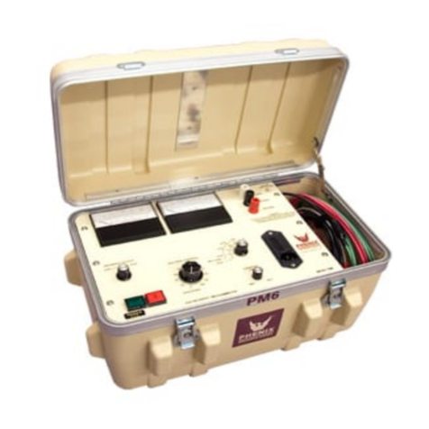
Phenix 635-5P User manual

PORTABLE AC DIELECTRIC TEST SET
Model Number 635-5P
LO/ch
October 17, 1997 +

TABLE OF CONTENTS
Section Number
DANGER
TECHNICAL SPECIFICATIONS 1
INTRODUCTION 2
SAFETY 3
CONTROLS AND INSTRUMENTATION / FIGURE 1 4
SET-UP AND OPERATION 5
ELECTRICAL SCHEMATICS 6
PARTS LIST 7
MAINTENANCE 8
WARRANTY 9
RETURNED MATERIAL 10
PARTS ORDERING INFORMATION 11
RECOMMENDED SPARE PARTS 12

1-1
TECHNICAL SPECIFICATIONS
INPUT: 120 VAC, 2 A, 1 phase, 60 Hz
OUTPUT: 0-35,000 VAC
Due to the short circuit current limiting of the 635-5P, the following maximum full
output voltages are available at the specified currents.
Output Current Approx. Max. Voltage Available
1 mA 32 kV
2 mA 27 kV
3 mA 24 kV
4 mA 20 kV
5 mA 15 kV
6 mA 10 kV
Current limited to <10 mA output on short circuit.
INSTRUMENTATION:
Voltmeter: 3 1/2 digit LCD display
Scale: 0-35.0 kVAC
Accuracy: +/-1% FS
Currentmeter: 3 1/2 digit LCD display
Scale: 0-10.0 mA AC
Accuracy: +/-1% FS
DIMENSIONS: 18.5" H x 13.5" W x 11" D; 66 lbs.
(470 mm H x 343 mm W x 279 mm D; 30 kg)

2-1
INTRODUCTION
The Phenix Model 635-5P is a portable AC Dielectric Test Set for performing dielectric strength
tests primarily on vacuum bottles. The test set may also be used for testing other samples which
are no load or light load (< 1 mA) in nature. A built-in self-protection feature current limits the
short circuit output current to safe levels, preventing damage to the test set. Under dead short
conditions, the output voltage will drop to zero.

3-1
SAFETY
Because the 635-5P is designed to supply high voltages, safeguards have been built into it.
These safeguards are only effective if safe work practices are also used. The test set and these
procedures have been designed for use by knowledgeable electrical workers who have been
properly trained in its use.
Please note the following:
1. The test set must be grounded. The third prong on the input power plug is for this purpose.
DO NOT REMOVE THIS PRONG.
2. The tests described here are to be used ONLY on DE-ENERGIZED and isolated
transformers.
3. HIGH VOLTAGES (LETHAL IN VALUE) ARE GENERATED DURING THE TESTS AND
EXTREME CAUTION MUST BE USED. FOLLOW ALL SAFETY PROCEDURES.
GROUND OBJECT UNDER TEST BEFORE TOUCHING.
4. High Voltage section is located in a plastic case. DO NOT touch case while high voltage is
energized. Do not touch high voltage output lead when high voltage is energized.
5. Maintain safe working distances when the test set is energized.

4-1
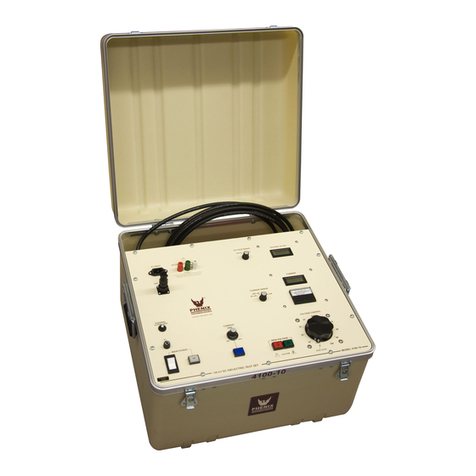
CONTROLS AND INSTRUMENTATION
The following is a brief description of the various controls and instrumentation found on the Model
635-5P.
Refer to Figure 1.
1. Main Power On Switch. Toggle switch supplies power to test set.
2. ON Indicator Lamp. Neon lamp indicates Main Power is ON.
3. Fuse. Overload protection for all control, metering, and power circuits.
4. High Voltage ON. "Deadman" pushbutton must be depressed and held to energize high
voltage. Pushbutton will light when high voltage is energized. Failure to hold down
pushbutton will cause high voltage to de-energize. Pushbutton is zero start interlocked.
5. Fault Indicator Lamp. Neon indicator lamp will glow or flicker indicating breakdown or
arcing within the object under test.
6. Voltage Adjust Knob. Controls output voltage from zero to full output voltage. Knob
must be in the zero or full counter clockwise position to energize high voltage.
7. Output Kilovoltmeter. Digital LCD display indicates output voltage. Scale: 0-35.0 KVAC.
8. Output Currentmeter. Digital LCD display indicates output current. Scale: 0-10.0 mAAC.

5-1
SET-UP AND OPERATION
1. Place unit on bench or other suitable flat surface.
2. Undo (2) latches on side of case.
3. Remove cover, power, control, return, and output cables. Exercise caution in removing cover
because control cables are permanently connected to the bottom of the case.
4. Separate High Voltage (bottom) section and control (cover) section to provide safe operating
distance between operator and high voltage.
5. Locate red high voltage output lead. Insert banana jack end of lead into jack provided on top
of high voltage section.
6. Connect high voltage and low voltage return leads to object under test.
7. Connect input power cord to a 117 VAC, 60 Hz grounded outlet.
8. Turn on Main Power toggle switch. Main Power indicator lamp should glow. Digital output
meters should now display zeros (+/-1 count).
9. Turn output voltage control knob to zero (full counter clockwise position). Depress high
voltage on pushbutton. Button should now glow indicating high voltage is energized. Raise
output voltage to desired test level by turning voltage control knob clockwise.
While raising the output voltage, pay special attention to the output currentmeter. If it should
suddenly show a high reading, this means the sample has broken down. Arcing or temporary
breakdowns will be indicated by the fault lamp.
10. At completion of high voltage test, return voltage control knob to zero and release high voltage
on pushbutton. High voltage on lamp should go out. If high voltage on pushbutton is released
while voltage control knob is off of zero, high voltage will deenergize and cannot be renergized
until voltage control knob is returned to zero.
11. To repack unit for transport, reverse step 3 above. Be sure to remove high voltage lead from
jack on top of high voltage section. Failure to do so may scratch or damage control panel.
A Note About Automatic Current Limit Circuit:
Unit is equipped with automatic current limit circuit which limits maximum output current to
approximately 10 milliamperes under dead short conditions. This feature consists of a high
impedance high voltage transformer combined with a series connected primary resistance to limit
the maximum current. This circuit will allow you to attain maximum output voltage when unit is
lightly loaded (less than 1 milliampere) while protecting the unit from damage when shorts or
breakdowns occur in the object under test.

6-1
ELECTRICAL SCHEMATICS
Drawing Number Description
1. -01-E634 Model 635-5P Portable AC Dielectric
2. -01-P118 Dual 5 VDC Power Supply PC Board
3. -01-P119 Meter Calibration PC Board

7-1
PARTS LIST
ITEM DESCRIPTION PART NO.
A1 PCB1165 Dual 5VDC Power Supply 31116500
A2 PCB1166 Meter Cal Board 31116600
BDG1 Diode Bridge 1789210
C1 Capacitor, .22µfd, 400V 1093170
C2 Capacitor, .01µf, 1kV 1092050
F1 Fuse, 5A, 250V, 3AG 1603605
Relay Socket, 3 Pole 1157620
J1 Corcom Connector 1152590
J2 10 Pin Female Recept. 1150128
J2 10 Pin Male Plug 1150129
Clamp 1150926
K1 Relay, 3PDT, 115VAC 1700610
M1-2 Meter, Acculex DP652 1506400
PL1,3 Lamp, Neon 115VAC 1423260
R1 Resistor, 2.7K Ohm, 2W 1712085
R2, A&B Resistor, 50 Ohm, 200W 1740208
Resistor, 500 Ohm, 50W 1741030
R3 Resistor, 10 Ohm, 2W 1710155
R4-2pcs. Resistor, 75M Ohm, 6W 1748200
R5 Resistor, 2K Ohm, 1/2W 1722078
R6 Resistor, 5K, 1/2W 1712110
R7 Resistor, 1.2M Ohm, 1/2W 1715996
S1 Switch, Toggle, DPDT 1865005
S2, PL2 Switch, Pushbutton, EAO 1860120
Lamp, 60V 1420150
Lens, Red 1422150
SCR1 SCR, C106D 1803100
SG1 Spark Gap, 90V 1605110
T1 Variac, Staco 221 1890105
T2 Transformer, HV, Phenix GV1118 38321118
Z1,2 5.6V Zener 1780034
Miscellaneous Components
Line Cord, 18/3, 8 ft. long 1077167
Case, Anvil 16”H x 9 ½”Dx 12”W 2100525
Return Lead, #10AWG, Hypalon 1078170
Clip #27C 1353042
Boot, Black 1353041
High Voltage Lead --
Clip #27C 1353042
Boot, Red #29 1353040
Plug, Banana, Red 1356200
Interconnect Cable, 4 Cond, 20AWG (2 pcs.) 1075040

8-1
MAINTENANCE
No solution or chemical stronger than ordinary mild soap and water solution should be applied to
the cabinet area of this unit. Care must be used when cleaning the meter faces and console
panel. Abrasives may remove printing and descriptive titles and scratch meter faces. When
cleaning, always have unit disconnected from power source. Never attempt to clean inside the
unit as the cleaning solution may cause damage to the electronic components.
In the event it becomes necessary to replace any parts, a complete description can be found with
the supplied parts list.

9-1
WARRANTY
Phenix Technologies, Inc. warrants to the original purchaser of any new merchandise that the
merchandise is free from defects in material and workmanship under normal use and service for a
period of 18 months from the date of shipment. The obligation of Phenix Technologies, Inc. under
this warranty is limited, in its exclusive option, to repair, replace, or issue credit for parts or
materials which prove to be defective, and is subject to purchaser's compliance with the Phenix
Technologies, Inc. warranty claim procedure as set forth below. The happening of any one or
more of the following events will serve to void this warranty and defect or damage resulting
therefrom is specifically excluded from warranty coverage:
A. Defects due to accident, negligence, alteration, modification, faulty installation by purchaser
or purchaser's agents or employees, abuse, or misuse.
B. Attempted or actual dismantling, disassembling, service or repair by any person, firm, or
corporation not specifically authorized in writing by Phenix Technologies, Inc.
C. Defects caused by or due to handling by carrier, or incurred during shipment, transshipment,
or other move.
This warranty covers only those parts and/or materials deemed by Phenix Technologies, Inc. to
be defective within the meaning of this warranty. The liability of Phenix Technologies, Inc. shall be
limited to the repair, replacement, or issuance of credit for parts deemed defective within the
meaning of this warranty. Costs incurred by purchaser for labor or other expenses incidental to
the inspection, repair, replacement, or issuance of credit for such parts and/or material shall be
the sole responsibility of purchaser. This warranty shall not apply to any accessories, parts, or
materials not manufactured or supplied by Phenix Technologies, Inc. and if, in the sole discretion
of Phenix Technologies, Inc., purchaser's claim relates to any materials or workmanship manu-
factured or performed by the supplier of a component part, or of the manufacturer of a device of
which the defective part is a component, Phenix Technologies, Inc. reserves the right to disclaim
liability under this warranty and to direct that the purchaser deal directly with such supplier or
manufacturer. Phenix Technologies, Inc. agrees to assist the purchaser in processing or settling
any such claims without prejudicing its position as to liability.
Warranty Claim Procedure
Compliance with the following warranty claim procedure is a condition precedent to the obligation
of Phenix Technologies, Inc. under this warranty.
A. Purchaser must notify Phenix Technologies, Inc. in writing by certified or registered mail, of
the defect claimed within 18 months after date of original shipment. Said notice shall
describe in detail the defect, the defective parts and/or part, and the alleged cause of defect.
B. At the exclusive option of Phenix Technologies, Inc., purchaser shall dismantle or dis-
assemble at purchaser's cost and expense and shall ship the defective part or material
prepaid to and from Phenix Technologies, Inc., Accident, Maryland 21520, for inspection, or
permit an authorized service representative of Phenix Technologies, Inc. to inspect the
defective part or material at purchaser's premises. If Phenix Technologies, Inc. shall inspect
the part or material at the purchaser's premises, purchaser shall provide facilities for, and at
purchaser's cost and expense, dismantle, disassemble, or otherwise make accessible the
subject part of material whether or not same is a component of or installed in a device other

9-2
WARRANTY
than that manufactured or supplied by Phenix Technologies, Inc. If disclosure shows that the
defect is not one for which Phenix Technologies, Inc. is liable, the purchaser agrees to
reimburse Phenix Technologies, Inc. for all expense incurred.
C. Upon receipt of the defective part or material, or after access to same, Phenix Technologies,
Inc. shall inspect the part or material to determine the validity of purchaser's claim.
The validity of any warranty claim, purchaser's compliance with Phenix Technologies, Inc.
warranty claim procedure, the obligation to either repair, replace, or issue credit, or direct the
purchaser to deal directly with a manufacturer or supplier are to be determined solely and
exclusively by Phenix Technologies, Inc. and any determination so made shall be final and
binding.
This warranty is expressly in lieu of all other warranties expressed or implied on the part of Phenix
Technologies, Inc., including the warranties or merchantability and fitness for use, and
consequential damages arising from any breach thereof and Phenix Technologies, Inc. neither
assumes nor authorizes any other person, firm, or corporation to assume any liability or obligation
in connection with this sale on its behalf and purchaser acknowledges that no representations
except those made herein have been made to purchaser.

10-1
RETURNED MATERIAL
If for any reason it should become necessary to return this equipment to the factory, the Service
Department of Phenix Technologies, Inc. must be given the following information:
Name Plate Information
Model Number
Serial Number
Reason for Return
Cause of Defect
If Phenix Technologies, Inc. deems return of the part appropriate, it will then issue an
"Authorization for Return".
If return is not deemed advisable, other inspection arrangements will be made.
NOTE: Material received at this plant without the proper authorization shall be held as
"Customer's Property" with no service until such time as the proper steps have been taken.
Your cooperation is requested in order to ensure prompt service.

11-1
PARTS ORDERING INFORMATION
Replacement parts are available from Phenix Technologies, Inc.
Changes to Phenix Technologies' products are sometimes made to accommodate improved
components as they become available, and to give you the benefit of the latest technical
improvements developed in our Engineering Department. It is, therefore, important when ordering
parts to include the serial number of the unit as well as the part number of the replacement part.
When your purchase order is received at our office, a representative of Phenix Technologies will
contact you to confirm the current price of the part being ordered. If a part you order has been
replaced with a new or improved part, an Applications Engineer will contact you concerning any
change in part number.
Your order for replacement parts should be sent to:
Replacement Parts Department
Phenix Technologies, Inc.
75 Speicher Drive
Accident, Maryland 21520

12-1
RECOMMENDED SPARE PARTS
In order to maintain your set in full operating condition with a minimum of down time, the following
spare parts should be kept on hand to avoid unnecessary phone calls, expensive modes of
shipment, delays in repairs, etc. Pricing is available upon request.
Quantity Description Part Number
1 Fuse, 250V, 5A 1603605
1 Bulb, 60VAC 1420150
1 Lamp, Neon, 115VAC 1423250
1 Meter, Digital, LCD 1506400
Table of contents
Other Phenix Test Equipment manuals