BBB MARK-B 1 User manual

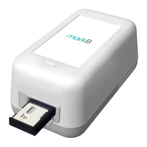
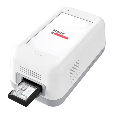
MARK-B™ 1 analyzer
User Manual
MARK-B™ 1 analyzer (Immunoassay analyzer) *Model: MB-100
MARK-B™ 1 analyzer detects specific biomarkers via immunoassay (MESIA;
Magnetic Electrochemical Sandwich ImmunoAssay) from a small amount of test
sample (e.g. whole blood). MARK-B™ 1 analyzer is intended to be used as an in
vitro diagnostic medical device. Please read this user manual thoroughly for
correct use and keep it for future reference.
IVD


Table of Content
1. Product Introduction ﹒﹒﹒﹒﹒ ﹒﹒﹒﹒﹒﹒﹒﹒﹒﹒﹒﹒﹒﹒﹒﹒﹒﹒﹒﹒﹒﹒﹒﹒﹒﹒﹒ 4
1-1. Intended Use ﹒﹒﹒﹒﹒﹒﹒﹒﹒﹒﹒﹒﹒﹒﹒﹒﹒﹒﹒﹒﹒﹒﹒﹒﹒﹒﹒﹒﹒﹒ ﹒ 4
1-2. Principle﹒﹒﹒﹒﹒﹒﹒﹒﹒﹒﹒﹒﹒﹒﹒﹒﹒﹒﹒﹒﹒﹒﹒﹒﹒﹒﹒﹒﹒﹒﹒﹒﹒﹒4
1-3. Precautions & Warnings ﹒﹒﹒﹒﹒﹒﹒﹒﹒﹒﹒﹒﹒﹒﹒﹒﹒﹒﹒﹒﹒﹒﹒﹒﹒﹒ 4
1-4. Components﹒﹒﹒﹒﹒﹒﹒﹒﹒﹒﹒﹒﹒﹒﹒﹒﹒﹒﹒﹒﹒﹒﹒﹒﹒﹒﹒﹒﹒﹒﹒﹒ 5
1-5. Symbol Guide﹒﹒﹒﹒﹒﹒﹒﹒﹒﹒﹒﹒﹒﹒﹒﹒﹒﹒﹒﹒﹒﹒﹒﹒﹒﹒﹒﹒﹒﹒﹒ 5
1. Product Description ﹒﹒﹒﹒﹒﹒﹒﹒﹒﹒﹒﹒﹒﹒﹒﹒﹒﹒﹒﹒﹒﹒﹒﹒﹒﹒﹒﹒﹒﹒﹒﹒﹒7
2-1. MARK-B™ 1 analyzer ﹒﹒﹒﹒﹒﹒﹒﹒﹒﹒﹒﹒﹒﹒﹒﹒﹒﹒﹒﹒﹒﹒﹒﹒﹒﹒﹒﹒7
2-2. Check Cartridge ﹒﹒﹒﹒﹒﹒﹒﹒﹒﹒﹒﹒﹒﹒﹒﹒﹒﹒﹒﹒﹒﹒﹒﹒﹒﹒﹒﹒﹒﹒ 8
2. Screen Description ﹒﹒﹒﹒﹒﹒﹒﹒﹒﹒﹒﹒﹒﹒﹒﹒﹒﹒﹒﹒﹒﹒﹒﹒﹒﹒﹒﹒﹒﹒﹒﹒﹒9
3-1. Home Screen ﹒﹒﹒﹒﹒﹒﹒﹒﹒﹒﹒﹒﹒﹒﹒﹒﹒﹒﹒﹒﹒﹒﹒﹒﹒﹒﹒ ﹒﹒ ﹒9
1. Initial Setup ﹒﹒﹒﹒﹒﹒﹒﹒﹒﹒﹒﹒﹒﹒﹒﹒﹒﹒﹒﹒﹒﹒﹒﹒﹒﹒﹒﹒﹒﹒﹒﹒﹒ ﹒﹒10
2. Running a Test ﹒﹒﹒﹒﹒﹒﹒﹒﹒﹒﹒﹒﹒﹒﹒﹒﹒﹒﹒﹒﹒﹒﹒﹒﹒﹒﹒﹒﹒﹒﹒﹒ ﹒﹒15
5-1. How to perform RUN TEST ﹒﹒﹒﹒﹒﹒﹒﹒﹒﹒﹒﹒﹒﹒﹒﹒﹒﹒﹒﹒﹒﹒﹒﹒ 15
5-2. Result Management ﹒﹒﹒﹒﹒﹒﹒﹒﹒﹒﹒﹒﹒﹒﹒﹒﹒﹒﹒﹒﹒﹒﹒﹒﹒﹒﹒﹒20
3. Running a QC Test (Control Solution Test) ﹒﹒﹒﹒﹒﹒﹒﹒﹒﹒﹒﹒﹒﹒﹒﹒﹒﹒﹒﹒﹒﹒ 21
4. Function Setting ﹒﹒﹒﹒﹒﹒﹒﹒﹒﹒﹒﹒﹒﹒﹒﹒﹒﹒﹒﹒﹒﹒﹒﹒﹒﹒﹒﹒﹒﹒﹒﹒﹒ 27
7-1. Setup Screen ﹒﹒﹒﹒﹒﹒﹒﹒﹒﹒﹒﹒﹒﹒﹒﹒﹒﹒﹒﹒﹒﹒﹒﹒﹒﹒﹒﹒﹒﹒﹒27
7-2. Administrator Settings ﹒﹒﹒﹒﹒﹒﹒﹒﹒﹒﹒﹒﹒﹒﹒﹒﹒﹒﹒﹒﹒﹒﹒﹒﹒﹒﹒ 28
7-3. Wi-Fi Settings ﹒﹒﹒﹒﹒﹒﹒﹒﹒﹒﹒﹒﹒﹒﹒﹒﹒﹒﹒﹒﹒﹒﹒﹒﹒﹒﹒﹒﹒﹒ 30
7-4. Printer Settings ﹒﹒﹒﹒﹒﹒﹒﹒﹒﹒﹒﹒﹒﹒﹒﹒﹒﹒﹒﹒﹒﹒﹒﹒﹒﹒﹒﹒﹒﹒ 31
7-5. Date & Time Settings ﹒﹒﹒﹒﹒﹒﹒﹒﹒﹒﹒﹒﹒﹒﹒﹒﹒﹒﹒﹒﹒﹒﹒﹒﹒﹒﹒ 32
7-6. Lock Settings ﹒﹒﹒﹒﹒﹒﹒﹒﹒﹒﹒﹒﹒﹒﹒﹒﹒﹒﹒﹒﹒﹒﹒﹒﹒﹒﹒﹒﹒﹒﹒ 34
1. Maintenance ﹒﹒﹒﹒﹒﹒﹒﹒﹒﹒﹒﹒﹒﹒﹒﹒﹒﹒﹒﹒﹒﹒﹒﹒﹒﹒﹒﹒﹒﹒﹒﹒﹒﹒﹒ 36
8-1. System Check ﹒﹒﹒﹒﹒﹒﹒﹒﹒﹒﹒﹒﹒﹒﹒﹒﹒﹒﹒﹒﹒﹒﹒﹒﹒﹒﹒﹒﹒﹒﹒36
8-2. Version Information and Update ﹒﹒﹒﹒﹒﹒﹒﹒﹒﹒﹒﹒﹒﹒﹒﹒﹒﹒﹒﹒﹒﹒﹒ 40
8-3 Device Registration﹒﹒﹒﹒﹒﹒﹒﹒﹒﹒﹒﹒﹒﹒﹒﹒﹒﹒﹒﹒﹒﹒﹒﹒﹒﹒﹒﹒﹒43
8-4. Auto Power Off Settings ﹒﹒﹒﹒﹒﹒﹒﹒﹒﹒﹒﹒﹒﹒﹒﹒﹒﹒﹒﹒﹒﹒﹒﹒﹒﹒ 45
8-5. Cleaning ﹒﹒﹒﹒﹒﹒﹒﹒﹒﹒﹒﹒﹒﹒﹒﹒﹒﹒﹒﹒﹒﹒﹒﹒﹒﹒﹒﹒﹒﹒﹒﹒﹒ 46
8-6. Storage Requirements ﹒﹒﹒﹒﹒﹒﹒﹒﹒﹒﹒﹒﹒﹒﹒﹒﹒﹒﹒﹒﹒﹒﹒﹒﹒﹒﹒ 46
1. Error Messages ﹒﹒﹒﹒﹒﹒﹒﹒﹒﹒﹒﹒﹒﹒﹒﹒﹒﹒﹒﹒﹒﹒﹒﹒﹒﹒﹒﹒﹒﹒﹒﹒﹒﹒47
10-1. Notifications ﹒﹒﹒﹒﹒﹒﹒﹒﹒﹒﹒﹒﹒﹒﹒﹒﹒﹒﹒﹒﹒﹒﹒﹒﹒﹒﹒﹒﹒﹒﹒ 47
10-2. Error pop-ups﹒﹒﹒﹒﹒﹒﹒﹒﹒﹒﹒﹒﹒﹒﹒﹒﹒﹒﹒﹒﹒﹒﹒﹒﹒﹒﹒﹒﹒﹒﹒51
1. Technical Information ﹒﹒﹒﹒﹒﹒﹒﹒﹒﹒﹒﹒﹒﹒﹒﹒﹒﹒﹒﹒﹒﹒﹒﹒﹒﹒﹒﹒﹒﹒﹒ 57
2. Product Warranty ﹒﹒﹒﹒﹒﹒﹒﹒﹒﹒﹒﹒﹒﹒﹒﹒﹒﹒﹒﹒﹒﹒﹒﹒﹒﹒﹒﹒﹒﹒﹒﹒ 58
3

1. Product Introduction
1-1. Intended Use
The MARK-B™ 1 analyzer is an instrument that performs immunoassay on test cartridges. It reads
specific biomarkers within the test sample.
When discarding the analyzer, discard in a safe place in accordance with the WEEE Directive
(2002/96/EC).
4
1-2. Principle
MARK-B™ 1analyzer is an instrument based on an immunoassay technique called MESIA (Magnetic
Electrochemical Sandwich Immunoassay). MARK-B™ 1analyzer can be used to analyze asingle or
multiple analyte(s) by detecting electrochemical signals on the test cartridge, which is for aone-time in
vitro diagnostic (IVD). The magnets within the device form magnetic fields, which facilitate the
interaction of nanoprobes in the test cartridge to induce antibody-antigen reactions and remove
unbound magnetic nanoprobes. The MARK-B™ 1analyzer measures the concentration of any
antigensor antibodies by detecting electrochemical signals from the reaction-completed magnetic
nanoprobes. MARK-B™ 1analyzer transmits the test data to the designated server via Wi-Fi.
1-3. Precautions &Warnings
Please read this user manual thoroughly for appropriate use.
MARK-B™ 1analyzer is for use in IVDs.
MARK-B™ 1analyzer and test cartridges are indicated for use in clinical laboratories.
Check that all components are present in the package.
Read this user manualbefore operating the analyzer.
The analyzer needs AC power connection to operate for an extended period of time and charge.
Please ensure your power supply is compatible with the analyzer’s power specifications.
Increasing the inner temperature activates the cooling fan inside the air vent.
Establish afree distance of at least 10 cm (4 inches) from the face of the air vent when installing the
device.
Keep the air vent free from inflow of foreign substances.
Accidental entry of metals into the analyzer may cause breakdown or electric shock.
Please refer to product-specific package inserts included in each test kit for more information.
Turn off the powerandremove the adapter if you do not expect to use the analyzer for an extended
period of time.
Do not use or store the product in alocation exposed to open flames.
Do not expose or store the product in alocation subject to high temperature and high humidity.
Prevent water and dust from entering the device.
Do not apply excessive force, drop or step on the product.
Avoid dropping the device while moving it.
Do not assemble or modify the analyzer.
The analyzer is not water-resistant. Do not wash it with water or touch it with wet hands.
Do not use the product to diagnose specific illnesses and conduct screening tests, such as neonatal
screening.
Use the analyzer only to assist medical decision-making.
Keep this product out of thereach of children.
In order to comply with radio frequency (RF) exposuer limits, antennas should be located at a
minimum of 20cm or more from the body all persons.

5
1. Product Introduction
1-4. Components
The following are the components you should check upon opening the package of MARK-B™
1 analyzer.
Please check that all components are included in the box.
Please contact the purchase location if any of the following components are not included or
damaged.
✔ MARK-B™ 1 analyzer, 1EA
✔ User manual
✔ Quick guide
1-5. Symbol Guide
Please refer to the following symbols that can be found on the external package, package
descriptions, enclosed papers, etc.

6
1. Product Introduction

2. Product Description
2-1. MARK-B™ 1 analyzer
Power button
Buttons to turn the device on or off.
Tray (closed)
A component to insert the test cartridge.
Opening and closing of the tray are controlled by the
software.
Screen
Interface that the user can touch to operate the analyzer
and check the results.
Tray (open)
The tray is open with the cartridge inserted.
(Component as closed status shown in .)
Air vent
A component to control temperature inside the analyzer.
Power supply connector
An adapter connection port to supply power to the
device.
Electrode connector for test cartridge
A connector for cartridge reading.
Cartridge recognition switch
A switch to check cartridge insertion.
USB port
A USB-A port for barcode scanner and mobile printer.
7
2
3
1
9
4
5
6
7
8
3

8
The check cartridge is used to evaluate instrumental and electronic operations of the
analyzer.
An alignment sensor is embedded in the check cartridge to check the alignment of magnets at
the top and bottom of the analyzer.
2-2. Check Cartridge
2. Product Description
Cartridge contact pad
Contact pad for the operation check of MARK-B™ 1
analyzer

3. Screen Description
3-1. Home Screen
Status bar
Indicates MARK-B™ 1 analyzer’s network
connection, battery level and time.
Status indicating icon
is displayed when QC test result shows
“fail” or the QC test is not carried out.
is displayed when battery level is 15%
or lower.
is displayed when temperature is either
15℃ or lower, or at least 30℃.
is displayed when the first System Check
is not performed, or System Check result
is Fail.
Time
Displays day, date and month.
Run test
Touch the button to start the test.
QC Test interval and test information
Check QC Test intervals and recent/next test
schedule of the QC test
Run QC Test
Touch the button to run the QC test.
Test results
Check all test results.
Admin login / logout
Login to / logout of the admin account.
Settings
Change settings.
Check device information and update it.
1
2
3
4
5
6
7
8
9
9
89
1
2
3
4
6
7
5

10
4. Initial Setup
Touch the ‘Select Time Zone’ → Select the time zone where the user is located.
→ When setting is completed, touch the ‘DONE’ button.
STEP 1. Connect the power adapter. STEP 2. Touch the ‘power’ button to start.
STEP 3. Time Zone setting

11
4. Initial Setup
Connect Wi-Fi → Select the Wi-Fi to connect to. → When connected, the ‘DONE’ button is
activated.→ Touch the ‘DONE’ button.
STEP 4. Wireless network (Wi-Fi) setting
Icon Connection Status Description
Connected Wi-Fi is connected and active.
Requesting
connection
Please wait as the Wi-Fi signal is being acquired. In the
case of no response, touch ‘Reconnect Wi-Fi’ to try again.
Connection Failure Wi-Fi connection has failed.
Check wireless connection status or select other Wi-Fi.
Network not
connected
The icon indicates that Wi-Fi is not connected.
Select the ‘Reconnect Wi-Fi’ to connect in-range
accessible Wi-Fi.

12 12
Enter admin password → Touch the ‘OK’ button
• Administrator ID is automatically set as ‘Admin’.
• Please set your own admin password.
• Password is case-sensitive and must be a combination of letters
and numbers.
• Your password cannot contain spaces and must be less than 45
characters long.
• Touch the eye-shaped icon to check entered password.
Establish QC Test settings according to each item → Touch the ‘OK’ button
QC Lock On
• In the case of when QC Test result shows ‘FAIL’,
the test is unavailable until the result shows ‘PASS’.
• Conduct QC test regularly as scheduled, otherwise test cannot be
run.
QC Lock OFF
• A test can be run regardless of QC Test results.
QC interval
• On : A test can only be run upon completion and passing of the QC
Test on the designated QC Test date
• OFF : Disables QC Test interval
• Interval setting : Set up QC Test interval within 1 to 365 days
STEP 5. Create Admin Password
STEP 6. Lock Setting
4. Initial Setup

4. Initial Setup
STEP 7. Device registration
• If there is no hospital for device registration, touch the ‘Register device later’ button.
• Device registration is available later in [‘Settings’ → ‘Device registration’] (see
Page 44).
13
a. Enter hospital code in the window.
b. After entering hospital code, touch the ‘DONE’ button to connect to hospital server.
c. Once connected to server, initial setup is completed and the home screen will be displayed.

14
4. Initial Setup
Printer is sold separately.
Barcode Scanner Connection
Printer Connection
Barcode scanner is sold separately.
a. Connect the barcode scanner to the USB Port on the back of MARK-B™ 1 analyzer.
b. Barcode scanner automatically starts operation when connected to the USB port.
a. Turn the printer on.
b. USB Connection
The printer is automatically recognized once USB cable is connected.
c. Bluetooth Connection
Please refer to [Function settings → Printer setting] on Page 32 of this manual.

15
5. Running a Test
5-1. How to Perform RUN TEST
a. Scan the code with a barcode scanner or type it using the keypad.
b. Touch the ‘OK’ button.
If you do not have a barcode
scanner, touch the ‘Input
operator ID manually’ to enter
the code using the keypad.
STEP 2. Operator code scan
STEP 1. Touch the ‘RUN TEST’ button to start test
• Operating temperature(Device without a cartridge) is -10 ~
45°C (14 ~ 113°F).
• Run test within the specified range of temperature.
• If the temperature is out of range, the test cannot be run.
• When the battery level becomes 15% or lower, the test cannot
be run.
• Fully charge the battery before running a test.

16
a. Scan the QR code on the cartridge pouch with a barcode
scanner.
b. After scanning the QR code, cartridge type and LOT code
are displayed on the screen.
If you do not have a barcode
scanner, touch the ‘Input patient
code manually’ to enter the code
using the keypad.
a. Scan the patient code with a barcode scanner.
b. When the code is inputted, proceed to the cartridge insertion.
• Barcode scanner is sold separately.
• If QR code recognition fails, scan a new cartridge pouch.
• Please check if the test marker is correct.
STEP 3. Patient code scan
STEP 4. Cartridge QR code scan
5. Running a Test
5-1. How to Perform RUN TEST

17
STEP 5. Test cartridge insertion
5. Running a Test
5-1. How to Perform RUN TEST
● If the tray does not move out, the device displays ‘Contact System Administrator’. In that
case, follow the instructions and contact the administrator.
a. Insert a test cartridge to the tray according to the
instructions on the screen.
b. When the cartridge is inserted in the correct position, the
screen automatically instructs to inject test sample.
• Ensure the correct operator and test sample code are entered before inserting a cartridge.
• Ensure the QR code of the cartridge to be inserted is scanned.
• Double check whether you are using the correct test cartridge for the marker.
• Before inserting a cartridge, ensure that you are not using an already used one.
• When ‘Please contact the system administrator’ message is displayed after inserting a
cartridge, stop using it and contact the administrator.

18
STEP 6. Test sample injection and starting test
5. Running a Test
5-1. How to Perform RUN TEST
a. Prepare a test sample.
b. Before injecting the sample, check injection location of the test sample and
whether a sufficient amount of test sample is prepared.
c. Inject the test sample within 2 minutes after inserting a cartridge.
d. After injection of the test sample is completed, touch the ‘OK’ button.
• When the analysis starts, please wait until analysis reaches ‘100%’.
• If the tray is not inserted into analyzer within 2 minutes after injected sample, start over
with a new cartridge.
• If an error occurs in waiting mode, inject more of the sample into the cartridge inserted.
• When an error occurs in analyzing mode, start over with a new cartridge.
• Refer to the test cartridge package insert for details on how to draw test samples.

19
5. Running a Test
5-1. How to Perform RUN TEST
STEP 8. Discard the used cartridge.
Refer to the images below to eject the cartridge from the tray.
Discard used cartridge in a safe place under relevant laws and regulations.
a. When test is completed, the result of the test is displayed on the same screen.
b. Check the result and remove the cartridge from the tray.
c. Touch the ‘DONE’ button → Return to the home screen.
STEP 7. Check the result of the test.
TEST RESULT: Positive or Negative
- Normal operation of test cartridge
If the warning sign is displayed as
shown:
“ * warning: unexpected signal
detected.”,
a retest is recommended.

20
5. Running a Test
5-2. Result Management
Check the results of the test.
- The results can be checked by touching the ‘TEST RESULTS’ button on the home screen.
Other manuals for MARK-B 1
1
Table of contents
Other BBB Measuring Instrument manuals
Popular Measuring Instrument manuals by other brands
Agilent Technologies
Agilent Technologies 4339B Operation manual
Chauvin Arnoux
Chauvin Arnoux PAC 20 user manual
YASKAWA
YASKAWA 1000 Series installation manual
PCB Piezotronics
PCB Piezotronics IMI SENSORS 623C11 Installation and operating manual
Extech Instruments
Extech Instruments PQ3450-30 user manual
Stahl
Stahl ConSig 8010 operating instructions
