manuals.online logo
Brands
  1. Home
  2. •
  3. Brands
  4. •
  5. BBC Bircher
  6. •
  7. Switch
  8. •
  9. BBC Bircher CleanSwitch Lock User manual

BBC Bircher CleanSwitch Lock User manual

1
   
  
88
3888
Ø 54
60
CleanSwitch Lock
       + 
    
x 38
y 38
z 42
30
x 88
y 92
z 80
x 88
y 92
z 80
x = Feller, y = Hager, z = Gira / Jung
x Ø 54
y Ø 54
z Ø 54
Feller / Hager Gira / Jung
88
min.
70 mm
2 3
4
1TOP TOP
1Safety instructions
Translation of the original instructions
General
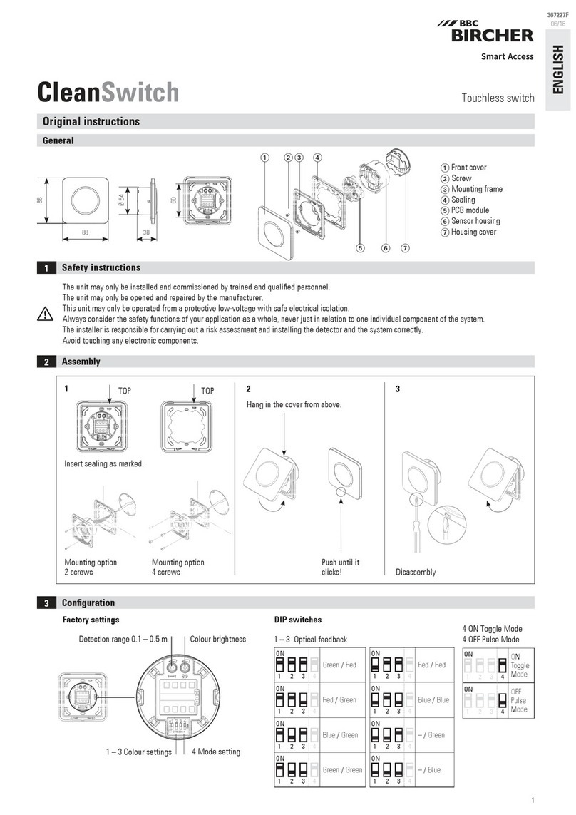
Front cover
 Screw
 Mounting frame
Seal
 Print module
 Sensor housing
Housing cover
Contact-free switch with digital input
for standard and integration for Feller, Hager, Gira and Jung switch systems
ENGLISH
419888A
11/20
The device may only be installed and commissioned by trained and qualied personnel.
The device may only be opened and repaired by the manufacturer.
The device may only be connected to a protection low-voltage system with safe electrical separation.
Always consider the safety functions of your application as a whole, never just in relation to one individual section of the system.
The installer is responsible for carrying out a risk assessment and installing the detector and the system correctly.
Avoid touching any electronic components.
Front cover
 Cover frame
 Screws
Mounting frame
 Sensor housing
 Print module
Housing cover
2Mounting
Insert the seal as marked.
Mounting option
2 screws
Mounting option
4 screws
Dismantling
Press until
it clicks!
Attach the cover at the top.Recommended mounting
distance between CleanSwitch
(horizontal and vertical)
Standard example
2
2 31

 
Feller / Hager Gira / Jung
Lock-Input – (+)
1
2
3
4
5
Supply – (+)
Supply + (–)
Relay COM
Relay NO
min.
8.5
Mount the mounting
frame in the correct
position
Mount the mounting
frame in the correct
position
Mounting with 4 screws Mounting with 2 screws Dismantling
Prepare cover frame
 Mount the front cover in the correct position
 Press until it clicks
Example with Feller / Hager
3Conguration
Detection range 0.1 – 0.5 m Colour brightness
4 Mode setting
1 – 3 Colour settings
ON
1 2 3 4
Green/red
ON
1 2 3 4
Red/green
ON
1 2 3 4
Blue/green
ON
1 2 3 4
Green/green
ON
1 2 3 4
Red/Red
ON
1 2 3 4
Blue/Blue
ON
1 2 3 4
–/Green
ON
1 2 3 4
–/Blue
ON
1 2 3 4
ON
Toggle
mode
ON
1 2 3 4
OFF
Pulse
mode
DIP switches
1-3 Optical feedback
4 ON Toggle mode
4 OFF Pulse mode
Factory settings
4Electric connections and operating principles
Stripping length min. 8.5 mm (solid wire or exible wire)
*Note: When the lock input is active, the sensor lights or ashes red 3 times,
independent of the setting of the DIP switches (chapter 3).
White
Red
Green
Grey
Blue
AWG 24 – 16/0.2 – 1.5 mm2
Lock input Activation Mode Relay output LED
OFF – Pulse/
Toggle OFF refer to
chapter 3
OFF Pulse
ON – Pulse (0.3 s)
refer to
chapter 3
Toggle ON
ON –
Pulse OFF
red*
Toggle if ON –
switches OFF
ON Pulse/
Toggle OFF
Flashing red
3 times*
• Solid wire > plug in
• Flexible wire > press button and
plug in
Supply + (–)
Supply – (+)
Relay COM
Relay NO
Lock input – (+)
Control unit
0 V
12–24V
Open
Control unit
Open
O V
CleanSwitch Lock
Modus: Pulse
CleanSwitch
Modus: Toggle
1
2
3
CleanSwitch Lock
Modus: Pulse
M
Control unit
~
~
Open
M
M
Control unit
0 V
+ 24 V
Open
CleanSwitch Lock
Modus: Pulse
CleanSwitch Lock
Modus: Pulse
Control unit
0 V
+ 24 V
Open
5
4
3
2
1
M
M
5
4
3
2
1
5
4
3
2
1
12–24V
5
4
3
2
1
5
4
3
2
1
External control system
Negative logic Negative logic
Open = 0 V DC Pulse Supply = 12–24 V AC
Open = +12–24 V DC Pulse
Blue
Grey
Green
Red
White
Blue
Grey
Green
Red
White
Blue
Grey
Green
Red
White
Blue
Grey
Green
Red
White
Blue
Grey
Green
Red
White
5Installation example
WC
Clean room
1
Mode
Pulse
2
Mode
Toggle
3
Mode
Pulse
4
Made in China / Designed in Switzerland
BBC Bircher Smart Access, BBC Bircher AG, Wiesengasse 20, CH-8222 Beringen, www.bircher.com
Technology Microwave Doppler Radar
Frequency 24.125 GHz
Detection range 0.1 – 0.5 m
Detection mode Pulse mode: The sensor detects during hand movement
Toggle mode: First movement on/second movement off
Detection speed Min: 5 Hz or ± 3 cm/s
Max: 200 Hz or ± 1.2 m/s
Supply voltage / Input 12-24 VAC ± 10% (50-60 Hz)
12-24 VDC + 20%/– 10%
Max. power consumption < 1 W (with optical feedback)
Output
Relay with NO contact (potential-free)
Max. switching voltage/switching current (DC): 1 A up to 30 V, 0.5 A up to 60 V
Max. switching voltage/switching current (AC): 1 A up to 50 V
Max. switching capacity: 30 W (DC)/50 VA (AC)
Output hold time "Relay hold time": 0.3 s
"LED hold time": 2 s
Storage/operating temperature – 20 to + 60˚C
Protection class Standard IP65 (xed with 4 screws, smooth surface)
Feller / Hager / Gira / Jung IP20
Dimensions (mm)
Standard / Feller 88 x 88 x 38 mm (L x W x D)
Hager 92 x 92 x 38 mm (L x W x D)
Gira / Jung 80 x 80 x 42 mm (L x W x D)
Weight 55 g
Materials Standard / Feller ASA / PC
Hager / Gira / Jung Duroplast / ASA / PC
6Technical data
Note: According to the VAH List, CleanSwitch is resistant to surface disinfectants in hospitals.
10 Contact
9FCC approval
See attachment
Devices with this symbol must be treated separately during disposal. This must be done in accordance with the laws of the
respective countries for environmentally sound disposal, processing and recycling of electrical and electronic equipment.
7EU Declaration of Conformity
8WEEE
This device meets the requirements of Part 15 of the FCC regulations and the RSS-210 standard of Industry Canada.
Warning: Changes or modications made to this device may void the FCC authorisation to operate this device.
Other BBC Bircher Switch manuals

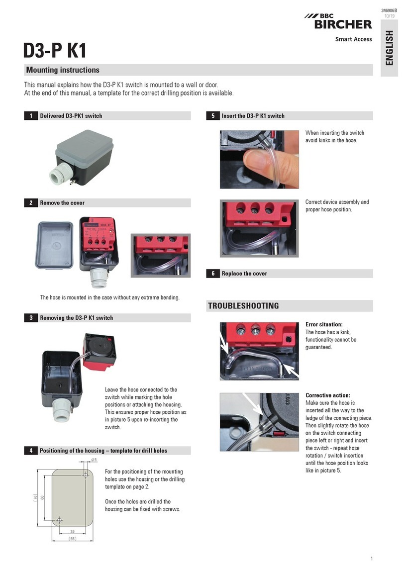
BBC Bircher D3-P K1 User manual

BBC Bircher

BBC Bircher D3-P K1 User manual

BBC Bircher CleanSwitch User manual

BBC Bircher

BBC Bircher CleanSwitch User manual

BBC Bircher ESD3 User manual

BBC Bircher

BBC Bircher ESD3 User manual

BBC Bircher ESR31C User manual

BBC Bircher

BBC Bircher ESR31C User manual

Popular Switch manuals by other brands

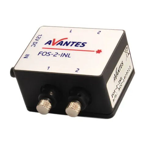
Avantes FOS-2-INL Operation and installation manual

Avantes

Avantes FOS-2-INL Operation and installation manual

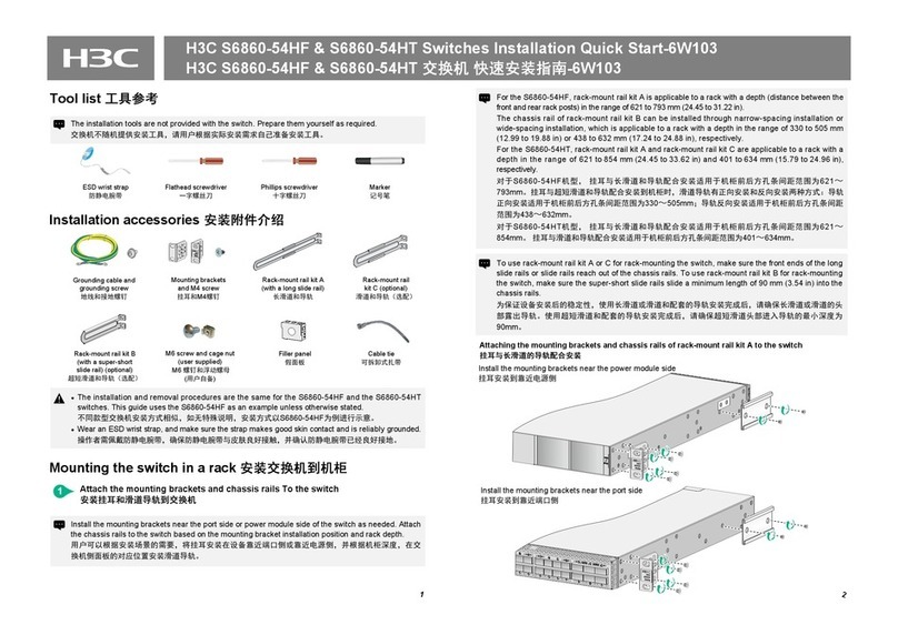
H3C S6860-54HF Installation, quick start

H3C

H3C S6860-54HF Installation, quick start

ANTAIRA LNX-0601G-SFP Quick installation guide

ANTAIRA

ANTAIRA LNX-0601G-SFP Quick installation guide

HP ProCurve 2610-48 specification

HP

HP ProCurve 2610-48 specification

Rockwell Automation Allen-Bradley Guard master 442G-MABH-Series user manual

Rockwell Automation

Rockwell Automation Allen-Bradley Guard master 442G-MABH-Series user manual

IBM SAN32M1 Installation and service manual

IBM

IBM SAN32M1 Installation and service manual

Murphy Temperature SWICHGAGE A20 Series owner's manual

Murphy

Murphy Temperature SWICHGAGE A20 Series owner's manual

UTAH SCIENTIFIC Utah-400 iP System setup and operations

UTAH SCIENTIFIC

UTAH SCIENTIFIC Utah-400 iP System setup and operations

IOGear UpStream Pro quick start guide

IOGear

IOGear UpStream Pro quick start guide

Lantronix SLC 8000 Series user guide

Lantronix

Lantronix SLC 8000 Series user guide

Havis DS-DA-601 owner's manual

Havis

Havis DS-DA-601 owner's manual

Master 21184.3 quick start guide

Master

Master 21184.3 quick start guide

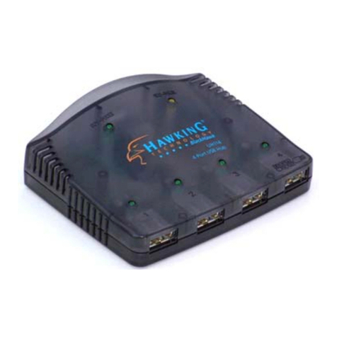
Hawking UH114 Specifications

Hawking

Hawking UH114 Specifications

Allied Telesis AT-x510-28GTX installation guide

Allied Telesis

Allied Telesis AT-x510-28GTX installation guide

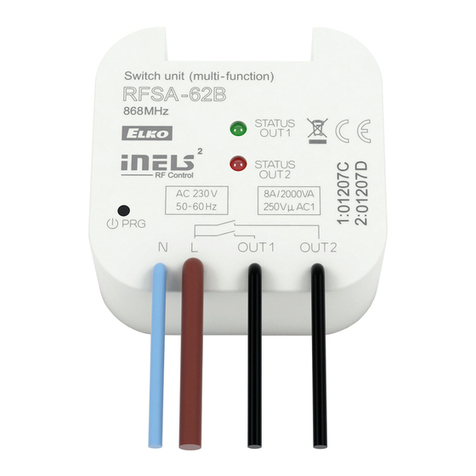
Elko RFSA-62B quick start guide

Elko

Elko RFSA-62B quick start guide

D-Link DGS-1210 Series manual

D-Link

D-Link DGS-1210 Series manual

Allied Telesis AT-8124XL installation guide

Allied Telesis

Allied Telesis AT-8124XL installation guide

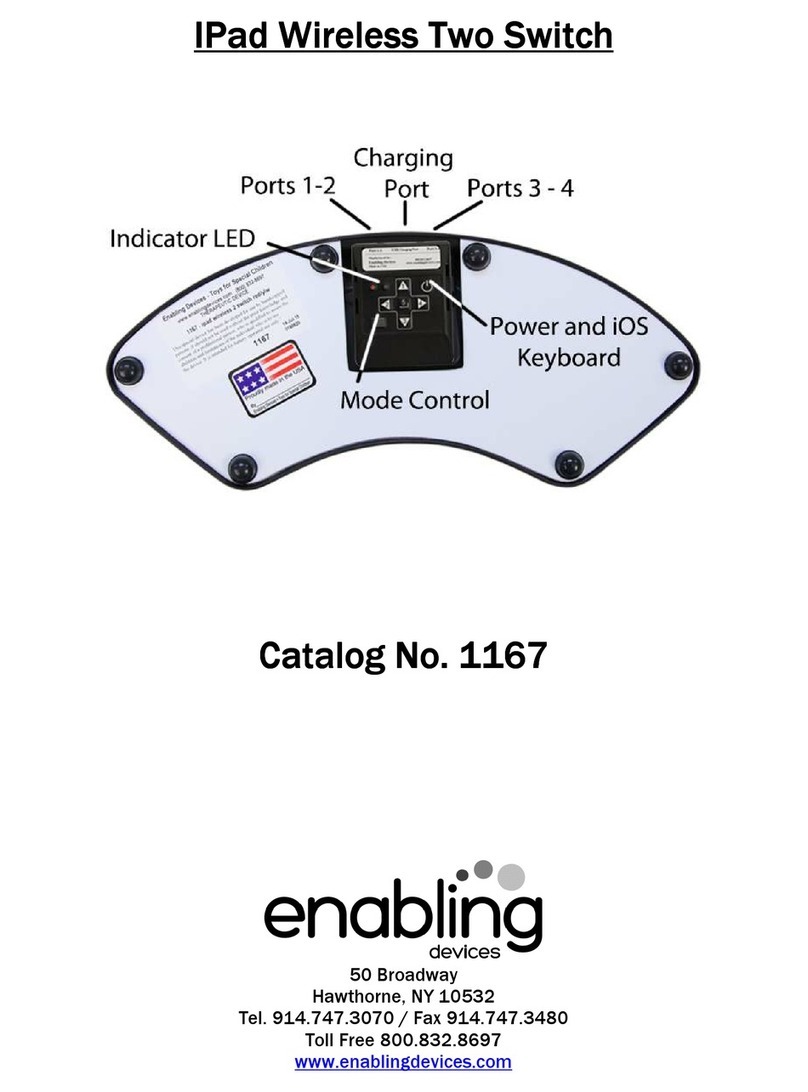
Enabling Devices 1167 instructions

Enabling Devices

Enabling Devices 1167 instructions

manuals.online logo
manuals.online logoBrands
  • About & Mission
  • Contact us
  • Privacy Policy
  • Terms and Conditions

Copyright 2025 Manuals.Online. All Rights Reserved.