BBK bbk940S User manual

TUNED ST. 3D
MEM
AM
ALL FM
SERVICE MANUAL
bbk940S
Downloaded From TheatreSystem-Manual.com Manuals

CONTENTS
1. SAFETY PRICAUTIONS 1
2. PREVENTION OF ELECTRO STATIC DISCHARGE(ESD)TO ELECTROSTATICALLY
SENSITIVE(ES)DEVICES 1
4. PREVERTION OF STATIC ELECTRICITY DISCHARGE 4
5. ASSEMBLING AND DISASSEMBLING THE MECHANISM UNIT 5
5.1 OPTICAL PICKUP UNIT EXPLOSED VIEW AND PART LIST 5
5.2 BRACKET EXPLOSED VIEW AND PART LIST 7
6. ELECTRICAL CONFIRMATION 9
6.1 VIDEO OUTPUT (LUMINANCE SIGNAL) CONFIRMATION 9
6.2 VIDEO OUTPUT(CHROMINANCE SIGNAL) CONFIRMATION 10
7. MPEG BOARD CHECK WAVEFORM 11
8. IC BLOCK DIAGRAM & DESCRIPTION 12
9. SCHEMATIC & PCB WIRING DIAGRAM 43
10. SPARE PARTS LIST 65
8.1 MT1336 12
8.2 MT1369 20
8.3 U214 HY29F800 31
8.4 U203 SDRAM-HY57V1610D 34
3. CONTROL BUTTON LOCATIONS AND EXPLANATIONS 2
5.3 MISCELLANEOUS 8
8.5 LX1722 35
8.6SI4558DY
39
Downloaded From TheatreSystem-Manual.com Manuals

4
3
7 8 9 10 11 12 13 14 15
6
5
2
2
Disc tray
7
STOP button 12 MIC 1 jack
4
VFD display window 9DVD MODE: PAUSE button
TUNER MODE: BAND button
14 MIC VOLUME knob
5
VOLUME knob DVD MODE PREV button
TUNER MODE TUNING button
10 15 ECHO adjustment knob
POWER switch
6
PLAY button DVD MODE: NEXT button
TUNER MODE: TUNING button
11
8FUNCTION button 13 MIC 2 jack
3
OPEN/CLOSE button
3.Control Button Locations and Explanations
Front Panel Illustration
TUNED
ST. 3D
MEM
AM
ALL FM
Downloaded From TheatreSystem-Manual.com Manuals

Change the audio language.
Switch the TV system between PAL, NTSC and AUTO.
DVD titles.
Switch audio channel.
Pause playback.
Normal playback.
Function setup.
Change subtitle languages/Switch JPEG display modes.
Adjust sound field effects.
Repeat playback.
Sleep timer.
Stations saving button, up to 20 FM/AM stations can
be saved respectively.
Slow playback.
SF button
14
AUDIO button
2
SUBTITLE button
3
L/R button
5
6P/N button
TITLE button
7
SLOW button
13
10 SETUP button
PLAY button
11
PAUSE button
12
NUMBERED buttons
4
Tuning up/down stations.
FWD/REV button
Fast forward/backward playback.
TUNING +/- buttons
19
MAN/AUTO button
20
Adjust EQ effects.
Manual/automatic tuning switch.
FM/AM switch.
Increase/decrease bass.
Increase/decrease treble.
Increase/decrease power amplifier's channel volume.
Select power amplifier's channel volume.
Turn off/on audio outputs
Increase/decrease the master volume.
Select the preset channels.
Select previous/next chapter or track when playing.
SAVE button
18
24 VOL +/- button
SPEAKERS button
25
BASS +/- button
22
TREBLE +/- button
23
MUTE button
27
PREVIOUS/NEXT button
PRESET +/- button
26
Play from the desired point.
Camera angles switch, MP3/JPEG playback modes switch.
DISC/RADIO/AUX IN switch.
GOTO button
36
ANGLE button
37
Open/Close the disc tray.
FUNCTION button
38
EJECT button
39
Power Spectrum Meter on/off.
PSM button
29
Repeat the selected section A-B.
MAIN VOL button
27
28
A-B button
2730
Back to the previous menu.
Display the disc menu, PBC ON/OFF button.
MENU button
33
Zoom in/out the playing frame.
Display the disc information.
ZOOM button
34
OSD button
35
Stop playback.
STOP button
31
RETURN button
32
BAND button
21
8DIRECTION ARROWS
SELECT button
9
6
3
2
5
7
8
9
12
11
13
14
15
16
39
38
37
34
35
36
32
33
19
18
20
21
22 23
24
25
26
29
30
31
28
27
17
4
10
REPEAT button
15
EQ button
17
SLEEP button
16
Enter or exit the standby mode.
STANDBY button
Control Button Locations and Explanations (Continued)
Remote Control Illustration
UP/DOWN/LEFT/RIGHT DIRECTION ARROW.
A-B
9 0 +10
56 7 8
1 2 34
STANDBY
EJECT
AUDIO
SUBTITLE ANGLE FUNCTION
GOTO
OSD
ZOOM
P/NL/R
TITLE
SELECT
SETUP RETURN
PLAY PAUSE STOP
SLOW REPEAT
MAIN
PSM
MUTE
BAND BASS VOL
MAN/AUTO
SAVE
SLEEP
TUNING
SF EQ
PRESET
SPEAKERS
TREBLE
MENU
VOL
Downloaded From TheatreSystem-Manual.com Manuals

5.1 Optical pickup Unit Explosed View and Part List
Pic (1)
Downloaded From TheatreSystem-Manual.com Manuals

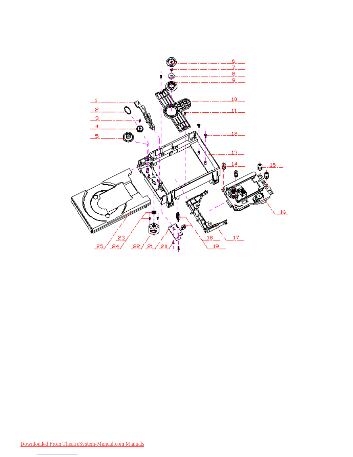
Materials to Pic (1)
No. PARTS CODE PARTS NAME Q ty
14692200 SF-HD60 1
1 1EA0311A06300 ASSY, CHASSIS, COMPLETE 1
2 1EA0M10A15500 ASSY, MOTOR, SLED 1
Or 1EA0M10A15501 ASSY, MOTOR, SLED 1
3 1EA2451A24700 HOLDER, SHAFT 3
4 1EA2511A29100 GEAR, RACK 1
5 1EA2511A29200 GEAR, DRIVE 1
6 1EA2511A29300 GEAR, MIDDLE, A 1
7 1EA2511A29400 GEAR, MIDDLE, B 1
8 1EA2744A03000 SHAFT, SLIDE 1
9 1EA2744A03100 SHAFT, SLIDE, SUB 1
10 1EA2812A15300 SPRING, COMP, TYOUSEI 3
11 1EA2812A15400 SPRING, COMP, RACK 1
21 1EA0B10B20100 ASSY, PWB 1
Or 1EA0B10B20200 ASSY, PWB 1
31 SEXEA25700--- SPECIAL SCREW BIN+-M2X11 3
32 SEXEA25900--- SPECIAL SCREW M1.7X2.2 2
33 SFBPN204R0SE- SCR S-TPG PAN 2X4 2
34 SFSFN266R0SE- SCR S-TPG FLT 2.6X6 1
35 SWXEA15400--- SPECIAL WASHER 1.8X4 X0.25 2
Note : This parts list is not for service parts supply.
Downloaded From TheatreSystem-Manual.com Manuals

5.2 Bracket Explosed View and Part List
Pic (2)
Materials to Pic(2)
1.bracket 14.frontsiliconrubber
2.belt15.Backsiliconrubber
3.screw 16.Pick-up
4.beltwheel 17.Pick-up
5.gearwheel 18.switch
6.ironchip 19.Five-pinflatplug
7. Immobility mechanism equipment 20. screw
8.Magnet 21.PCB
9.Platen 22.motor
10.Bridgebracket 23.Motorwheel
11.screw 24.screw
12.screw 25.tray
13. Big bracket
Before going process with disassembly and installation, please carefully both
peruse the chart and confirm the materials.
Downloaded From TheatreSystem-Manual.com Manuals

5.3 MISCELLANEOUS
5.3.1 Protection of the LD(Laser diode)
Short the parts of LD circuit pattern by soldering.
5.3.2 Cautions on assembly and adjustment
Make sure that the workbenches,jigs,tips,tips of soldering irons and measuring instruments are
grounded,and that personnel wear wrist straps for ground.
Open the LD short lands quickly with a soldering iron after a circuit is connected.
Keep the power source of the pick-up protected from internal and external sources of electrical
noise.
Refrain from operation and storage in atmospheres containing corrosive gases (such as H2S,SO2,
NO2 and Cl2)or toxic gases or in locations containing substances(especially from the organic silicon,cyan,
formalin and phenol groups)which emit toxic gases.It is particularly important to ensure that none of the
above substances are present inside the unit.Otherwise,the motor may no longer run.
Downloaded From TheatreSystem-Manual.com Manuals

6.1. Video Output (Luminance Signal) Confirmation
DO this confirmation after replacing a P.C.B.
Purpose:To maintain video signal output compatibility.
1.Connect the oscilloscope to the video output terminal and terminate at 75 ohms.
2.Confirm that luminance signal(Y+S)level is 1000mVp-p±30mV
Measurement point
Video output terminal
Color bar 75%
PLAY(Title 46):DVDT-S15
PLAY(Title 12):DVDT-S01
DVDT-S15
or
DVDT-S01
Mode Disc
Measuring equipment,tools
200mV/dir,10 sec/dir 1000mVp-p±30mV
Confirmation value
Downloaded From TheatreSystem-Manual.com Manuals

Do the confirmation after replacing P.C.B.
Purpose:To maintain video signal output compatibility.
1.Connect the oscilloscope to the video output terminal and terminate at 75 ohme.
2.Confirm that the chrominance signal(C)level is 621 mVp-p±30mV
Measurement point
Video output terminal
Color bar 75%
PLAY(Title 46):DVDT-S15
PLAY(Title 12):DVDT-S01
DVDT-S15
or
DVDT-S01
Mode Disc
Measuring equipment,tools Confirmation value
Screwdriver,Oscilloscope
200mV/dir,10 sec/dir 621mVp-p±30mV
Downloaded From TheatreSystem-Manual.com Manuals

Downloaded From TheatreSystem-Manual.com Manuals

MT1336
PRELIMINARY, SUBJ ECT TO CHANGE WITHOUT NOTICE MTK CONFIDENTIAL, NO DISCLOSURE
GENERALDESCRIPTION
MT1336 is a high performance CMOS analog front-end IC for both CD_ROM driver up to 48XS and
DVD-ROM driver up to 16XS. It also supports DVD-RAM read up to 4XS Version 2. It contains servo amplifiers
to generate focusing error, 3-beam tracking error, 1 beam radial push-pull signal, RF level and SBAD for servo
functions. It also includes DPD tracking error signal for DVD_ROM application. For DVD-RAM disks, there are
also Differential Push-Pull (DPP) method for generating tracking signal and Differential Astigmatic Detection
(DAD) for processing focusing signal. Programmable equalizer and AGC circuits are also incorporated in this
chip to optimize read channel performance. In addition, this chip has dual automatic laser power control circuits
for DVD-ROM (DVD-RAM) and CD-ROM seperately and reference voltage generators to reduce external
components. Programmable functions are implemented by the access of internal register through bi-directional
serial port to configure modes selection.
FEATURES
nRF equalizer with programmable c
ffrom 3MHz to 70 MHz and programmable boost from 3dB to
13dB.
nMT1336 supports at least eight different kinds of pick-up heads with versatile input configuration for
both RF input stages and servo signal blocks.
nVersatile on-line AGC.
n3 beams tracking error signal generator for CD_ROM application.
nOne beam differential phase tracking error (DPD) generator for DVD_ROM application.
nDifferential push pull tracki ng error (DPP) generator for DVD_RAM application.
nFocusing error signal generator for CD-ROM, DVD-ROM and DVD-RAM (DAD method).
nRF level signal generator.
nSub-beam added signal for 3 beams CD_ROM.
nOne beam push-pull signal generator for central servo application.
nHigh speed RF envelop detection circuit with bandwidth up to 400KHz for CD-ROM.
nDefect and Blank detection circuits.
nDual automatic laser power control circuits with programmable level of LD monitor voltage.
nVref=1.4V voltage and V2ref=2.8V voltage generators.
nV20=2.0V voltage for pick-up head reference.
nBi-directional serial port to access internal registers.
Downloaded From TheatreSystem-Manual.com Manuals

MT1336
PRELIMINARY, SUBJ ECT TO CHANGE WITHOUT NOTICE MTK CONFIDENTIAL, NO DISCLOSURE
MT1336 FUNCTION BLOCKS DIAGRAM
DVDA
DEFECT
TEO
FEO
MDI2
LDO2
ATTENUATOR
DPD
REF and 2VREF
Voltage Generator
V2REFO
LVL
VGA
ENVELOP
DETECTOR
AGC
RFGCU
LRFRP
INPUT MUX
REF and 2VREF
Voltage Generator
VGA EQ
ENVELOP
DETECTOR
AGC
CDA
DVDB
CDB
DVDC
CDC
DVDD
CDD
DVDRFIN
DVDRFIP
TPI
TNI
RFOP
SBAD
TE
RF
LEVEL
FE
DVD
APC
MDI1
LDO1
CD
APC
VREFO
SLCK
SDEN
SERIAL
PORT
DPFN
DPFO
IR
DPDMUTE
CRTP
OSP
OSN
RFON
CRTPLP
RFGC
MA
CENTRAL
SERVO
RFGCI
AGC3
AGC1
AGC2
CSO
HALLSIN
SINPHI
HRFRP
MB
MC
MD
CDFOP
CDFON
SA
SB
SC
SD
V20
RFSUBO
WOBBLE
DET
WOBSO
COSPHI
REFSIN
REFCOS
HALLCOS
PCS
UDGATE
IDGATE
VFO13
SDATA
Downloaded From TheatreSystem-Manual.com Manuals

MT1336
PRELIMINARY, SUBJ ECT TO CHANGE WITHOUT NOTICE MTK CONFIDENTIAL, NO DISCLOSURE
MT1336 PIN ASSIGNMENT
DPDMUTE
AGNDP
AGNDX
AVDDP
VCON
SA
SB
MC
MD
DVDB
DVDA
DVDRFIP
DVDC
DVDD
95
94
93
92
91
90
89
88
87
86
85
84
83
82
81
80
79
78
77
76
75
74
73
72
71
70
69
68
67
66
65
101
100
99
98
97
96
102
MT1336
DVD-ROM
With
DVD_RAM
Read
AVDDO
RFOP
RFON
AGNDO
TM1
TM2
TM3
AGNDT
TM4
AVDDT
IO4
SCLK
AGNDX
SW1
SWO
GNDS
CDB
CDA
DVDRFIN
AGNDF
MON
VFO13
AGNDX
AGNDX
TRLPA
TRLP
HTRC
GNDP
DPFN
DPFO
IO1
AGNDX
VDD
IO5
IO7
IO8
IO9
FEO
IOB
SW2
IOA
1
2
3
4
5
6
7
8
9
10
11
12
13
15
16
17
18
19
20
21
22
23
24
26
27
28
29
30
31
32
33
34
35
37
38
14
25
36
IO0
AVDDF
IO6
AGNDX
AVDDM
HALLCOS
COSPHI
REFCOS
AGNDM
HALLSIN
UDGATE
HDGATE
39
40
41
42
43
45
46
47
49
50
51
52
54
53
55
56
57
58
59
60
61
62
63
64
44
48
IR
AVDD
SC
SD
WGND
LDO2
MDI2
MDI1
CDFOP
SVDD
TPI
TNI
SGND
RFSUBO
WOBSO
WVDD
LDO1
WAVDD
AGC1
AGC2
AGC3
WAGND
121
120
119
118
117
116
115
114
113
112
111
110
109
108
107
106
105
104
103
127
126
125
124
123
122
128
AGND
RST
SDATA
SDEN
V2REFO
LRFRP
HRFRP
CRTP
CRTPLP
DEFECT
VDDP
TEO
CSO
VREFO
V20
LVL
VDDS
MB
RFGC
RFGCU
RFGCI
CEQP
CEQN
AGNDX
XCK16M
IO3
GND
REFSIN
MOP
CDC
CDD
MA
OSN
OSP
IO2
CDFON
SINPHI
AGNDX
AGNDX
Downloaded From TheatreSystem-Manual.com Manuals

MT1336
PRELIMINARY, SUBJ ECT TO CHANGE WITHOUT NOTICE MTK CONFIDENTIAL, NO DISCLOSURE
MT1336 PIN DESCRIPTIONS
Pin Numbers Symbol Type Description
LQFP128
RF Flag Interface
23 DEFECT Digital Output Flag of bad data output status
RF SIO interface
56 SCLK Digital Input RF serial clock input
58 SDEN Digital Input RF serial data enable
59 SDATA Digital IO RF serial data IO
60 RST Digital input Reset (active high)
55 XCK16M Digital Input 16.9MHz for verification
RF SERVO interface
40 UDGATE Digital Input Con trol signal for DVD-RAM
41 IDGATE Digital Input Control signal for DVD-RAM
38 VFO13 Digital Input DVD -RAM Header signal
RF
100 DVDA Analog input AC coupled DVD RF signal input A
99 DVDB Analog Input AC coupled DVD RF signal input B
98 DVDC Analog Input AC coupled DVD RF signal input C
97 DVDD Analog Input AC coupled DVD RF signal input D
95 DVDRFIN Analog Input AC coupled DVD RF signal input RFIN
96 DVDRFIP Analog Input AC coupled DVD RF signal input RFIP
94 CDA Analog Input AC coupled CD RF signal input A
93 CDB Analog Input AC coupled CD RF signal input B
92 CDC Analog Input AC coupled CD RF signal input C
91 CDD Analog Input AC coupled CD RF signal input D
90 OSN Analog RF Offset cancellation capacitor connecting
89 OSP Analog RF Offset cancellation capacitor connecting
85 CEQP Analog RF Offset cancellation capacitor connecting
84 CEQN Analog RF Offset cancellation capacitor connecting
88 RFGC Analog RF AGC loop capacitor connecting for DVD -ROM
Downloaded From TheatreSystem-Manual.com Manuals

MT1336
PRELIMINARY, SUBJ ECT TO CHANGE WITHOUT NOTICE MTK CONFIDENTIAL, NO DISCLOSURE
87 RFGCU Analog RF AGC loop capacitor connecting for DVD -RAM
86 RFGCI Analog RF AGC loop capacitor connecting for DVD -RAM
101 MA Analog Input DC coupled DVD-RAM main-beam RF signal input A
102 MB Analog Input DC coupled DVD-RAM main-beam RF signal input B
103 MC Analog Input DC coupled DVD-RAM main-beam RF signal input C
104 MD Analog Input DC coupled DVD-RAM main-beam RF signal input D
105 SA Analog Input DC coupled DVD-RAM sub-beam RF signal input A
106 SB Analog Input DC coupled DVD-RAM sub-beam RF signal input B
110 SC Analog Input DC coupled DVD-RAM sub-beam RF signal input C
111 SD Analog Input DC coupled DVD-RAM sub-beam RF signal input D
108 IR Analog External current bias resistor (R=20K)
119 AGC1 Analog Wobble AGC loop1 capacitor
121 AGC2 Analog Wobble AGC loop2 capacitor
122 AGC3 Analog Wobble AGC loop3 capacitor
127 RFSUBO Analog output Header push-pull RF output signal
1WOBSO Digital output Wobble signal output
6RFOP Analog output RF positive output
7RFON Analog output RF negative output
TRACKING ERROR
32 DPFN Analog DPD amplifier negative input
33 DPFO Analog DPD amplifier output
61 DPDMUTE Digital input DPD mute control input
116 TNI Analog Input 3 beam satellite PD signal negative input
115 TPI Analog Input 3 beam satellite PD signal positive input
21 TEO Analog Output Trackingerroroutput
FOCUSING ERROR & RF LEVEL & CENTRAL SERVO SIGNAL
112 CDFOP Analog Input CD focusing error positive input
113 CDFON Analog Input CD focusing error negative input
18 FEO Analog Output Focusingerroroutput
19 LVL Analog Output RFleveloutput
20 CSO Analog output Central servo signal output
ALPC
Downloaded From TheatreSystem-Manual.com Manuals

MT1336
PRELIMINARY, SUBJ ECT TO CHANGE WITHOUT NOTICE MTK CONFIDENTIAL, NO DISCLOSURE
124 MDI1 Analog Input Laser power monitor input
125 LDO1 Analog Ou tput Laser driver output
123 MDI2 Analog Input Laser power monitor input
126 LDO2 Analog Output Laser driver output
RFRIPPLE
26 CRTP Analog RF top envelop filter capacitor connecting
27 CRTPLP Analog Defect level filter capacitor connecting
25 HRFRP Analog output High frequency RF ripple output or Blank detector’s output
24 LRFRP Analog output Low frequency RF ripple output
POWER
67, 69 AVDD Power Master PLL Filter power
65, 73 AGND GND GND for Master PLL Filter
64 AVDD Power DPD Power
62 AGND GND DPD GND
109 AVDD Power RFpathPower
107 AGND GND RFpathGND
114 SVDD Power Servo Power
117 SGND GND Servo GND
2,120 WAVDD Power Wobble Power
128,118 WAGND GND Wobble GND
5 AVDDO Power Power for RF output
8 AGNDO GND GND for RF output
14 AVDDT Power Power for Trimming PAD
12 AGNDT GND GND for Trimming PAD
22 VDDP Power Peak Detection Power
31 GNDP GND Peak Detection GND
37,54 VDD Power Serial I/O Power
39,57 GND GND Serial I/O GND
REFERENCE VOLTAGE
16 VREFO Analog output Reference voltage 1.4V
15 V2REFO Analog output Reference voltage 2.8V
17 V20 Analog Output Reference voltage 2.0V
Downloaded From TheatreSystem-Manual.com Manuals

MT1336
PRELIMINARY, SUBJ ECT TO CHANGE WITHOUT NOTICE MTK CONFIDENTIAL, NO DISCLOSURE
ALPC TRIMMING
9TM1 Analog input Trimming pin for ALPC1
10 TM2 Analog input Trimming pin for ALPC1
11 TM3 Analog input Trimming pin for ALPC2
13 TM4 Analog input Trimming pin for ALPC2
HIGH SPEED TRACK COUNTING
29 TRLP Analog Low-pass filter capacitor connecting
28 TRLPA Analog Low-pass filter capacitor connecting
30 HTRC Digital output High speed track counting digital output
PCS
74 HALLSIN Analog input Negative input of amplifier for hall sensor signal
75 REFSIN Analog input Positive input of amplifier for hall sensor signal
76 SINPHI Analog outputAmplifier output for hall sensor signal
71 HALLCOS Analog input Negative input of amplifier for hall sensor signal
72 REFCOS Analog input Positive input of amplifier for hall sensor signal
70 COSPHI Analog output Amplifier output for hall sensor signal
FOR MONITOR ONLY
81 MON Analog output
80 MOP Analog output
66 VCON Analog output
77 SWO Analog output Output from mux of SW1 & SW2
78 SW2 Analog input External input for servo input select
79 SW1 Analog input External inputfor servo input select
FOR SERIAL I/O
42 IO0
43 IO1
44 IO2
45 IO3
46 IO4
47 IO5
Downloaded From TheatreSystem-Manual.com Manuals

MT1336
PRELIMINARY, SUBJ ECT TO CHANGE WITHOUT NOTICE MTK CONFIDENTIAL, NO DISCLOSURE
48 IO6
49 IO7
50 IO8
51 IO9
52 IOA
53 IOB
Downloaded From TheatreSystem-Manual.com Manuals

MT1369
Specifications are subject to change without notice DVD Player Combo Chip
FEATURES
nSuper Integration DVD player single chip
§Servo controller and data channel processing
§MPEG-1/MPEG-2/JPEG video decoding
§AC-3/DTS/DVD-Audio/MP3 audio decoding
§Unified track buffer and A/V decoding buffer
§Video processing for scaling and video quality
enhancement
§OSD & Sub-picture decoding
§Built-in clock generator
nSpeed Performance on Servo and Decoding
§DVD-ROM up to 8XS
§CD-ROM up to 24XS
§Built-in a frequency programmable clock toµP
and RSPC Decoder to optimize the performance
over power
nChannel DataProcessor
§Provides interface with analog front-end
processor
§Analog data slicer for small jitter capability
§Built-in high performance data PLL for channel
data demodulation
§EFM/EFM+ data demodulation
§Enhanced channel data frame sync protection &
DVD-ROM sector sync protection
nServo Control and Spindle Motor Control
§Programmable frequency error gain and phase
error gain of spindle PLL to control spindle motor
on CLV and CAV mode
§Provide a varipitch speed control for CLV and CAV
mode
§Built-in ADCs and DACs for digital servo control
§Provide 2 general PWM
§Tray control can be PWM output or digital output
§Built-in DSP for digital servo control
nHost Micro controller
§Built-in 8032 micro controller
§Built-in internal 373 and 8-bit programmable
loweraddressport
§256-bytes on-chip RAM
§Upto1MbytesFLASH-programming interface
§Supports 5/3.3-Volt. FLASH interface
§Supports power-down mode
§Supports additional serial port
nDVD-ROM/CD-ROM Decoding Logic
§Supports CD-ROM Mode 1, CD-ROM XA Mode 2
Form 1, CD-ROM XA Mode 2 Form 2, and CD-DA
formats
§High-speed ECC logic capable of correcting one
error per each P-codeword or Q-codeword
§Automatic sector Mode and Form detection
§Automatic sector Header verification
§8-bit counter for decode completion check
§Programmable descrambling and error
correction schemes
§Automatically repeated error corrections
§8-bit C2 Pointer counter
§Decoder Error Notification Interrupt that signals
various decoder errors
§Provide error correction acceleration
nBuffer Memory Controller
§Supports 16Mb/32Mb/64Mb SDRAM
§Supports 16-bit/32-bit SDRAM data bus interface
§Build in a DRAM interface programmable clock to
optimize the DRAM performance
§Provide the self-refresh mode SDRAM
§Programmable DRAM access cycle and refresh
cycle timings
§Block-based sector addressing
§Programmable buffering counter for buffer status
tracking
§Maximum DRAM speed is 133MHz
§Support 5/3.3-Volt. DRAM Interface
Downloaded From TheatreSystem-Manual.com Manuals
Table of contents
Other BBK Home Theater System manuals