BBT SP70 User manual

OWNER’S MANUAL
Assembly & Operating Instructions
SELF PROPELLED LAWN MOWER
MODEL NO. BBT-SP70

2
WWW.BBTA.COM.AU BBT-SP70
To The Owner
Thank you for purchasing our Lawn Mower. It was carefully engineered to provide excellent performance when
properly operated and maintained.
Please read this entire manual prior to operating the Lawn Mower. It instructs you how to safely and easily set
up, operate and maintain your Lawn Mower. Please be sure that you and any other persons who will operate
the Lawn Mower carefully follow the recommended safety practices at all times. Failure to do so could result in
personal injury or property damage.
All information in this manual is relative to the most recent product information available at the time of printing.
Review this manual frequently to familiarise yourself with the machine, its features and operation. Please be
aware that this Owner’s Manual may cover a range of product specifications for various models. Characteristics
and features discussed and/or illustrated in this manual may not be applicable to all models. We reserve the right
to change product specifications, designs and equipment without notice and without incurring obligation.
All the power testing information used to establish the power rating of the engine equipped on this Lawn
Mower can be found in the engine manufacturer’s manual or website. If you have any problems or questions
concerning the machine, please contact our Customer Support Department.
Throughout this manual, all references to right and left side of the Lawn Mower are observed from the operating
position. The engine manufacturer is responsible for all engine-related issues with regards to performance,
power-rating, specifications, warranty and service. Please refer to the engine manufacturer’s Owner’s Manual
packed separately with your Lawn Mower for more information.
Customer Support
Please do NOT return the Lawn Mower without first contacting the Customer Support Department at
bbt@bbta.com.au.
If you have difficulty assembling this product or have any questions regarding the controls, operation, or
maintenance of this Lawn Mower, please contact our Customer Support Department.
SAVE THESE INSTRUCTIONS

3
WWW.BBTA.COM.AUBBT-SP70
TABLE OF CONTENTS
Page(s)
To The Owner.........................................................................................................................................................2
Customer Support..................................................................................................................................................2
TABLE OF CONTENTS .............................................................................................................................3
IMPORTANT SAFETY INFORMATION ................................................................................................. 4-5
Additional Information and Potential Changes...................................................................................................4
Key to Symbols.......................................................................................................................................................5
SAFETY INFORMATION ...................................................................................................................... 6-9
Preparation ............................................................................................................................................................6
Operation ...............................................................................................................................................................6
Maintenance and Storage.....................................................................................................................................7
Special Safety Instructions.....................................................................................................................................7
Fuel Handling.........................................................................................................................................................8
Intended Use .........................................................................................................................................................8
PARTS LOCATION....................................................................................................................................9
ASSEMBLY....................................................................................................................................... 10-11
OIL AND FUEL FILLING .........................................................................................................................12
Filling the Fuel Tank.............................................................................................................................................12
Oil Tank.................................................................................................................................................................12
OPERATION...........................................................................................................................................13
Starting the Engine..............................................................................................................................................13
Stopping the Engine ...........................................................................................................................................13
Self-Propeller Function .......................................................................................................................................13
Work Instructions.................................................................................................................................................13
MAINTENANCE & STORAGE .......................................................................................................... 14-15
Blade.....................................................................................................................................................................14
Spark Plug ............................................................................................................................................................15
Air Filter................................................................................................................................................................15
Adjusting the Transmission Cable .......................................................................................................................15
Storage .................................................................................................................................................................15
SPECIFICATIONS....................................................................................................................................16
WARRANTY & SERVICE ........................................................................................................................17
EXPLODED DIAGRAM & PARTS LIST.............................................................................................. 18-21
Component Parts Diagram..................................................................................................................................18
Engine Parts Diagram ..........................................................................................................................................20
YOU MAY ALSO LIKE ...........................................................................................................................22

4
WWW.BBTA.COM.AU BBT-SP70
IMPORTANT SAFETY INFORMATION
Additional Information and Potential Changes
We reserve the right to discontinue, change, and improve our products at any time without notice or obligation
to the purchaser. The descriptions and sections contained in this manual were in effect at the time of printing.
Equipment described within this manual may be optional. Some illustrations may not be applicable to your
machine.
WARNING: Read and thoroughly understand all instructions in this manual and on the safety decals
before assembling or operating this Lawn Mower. Failure to do so may cause serious injury or death.
Do not allow anyone to operate this Lawn Mower who has not read this manual. As with all power
equipment, a Lawn Mower can be dangerous if assembled or used improperly. Do not operate
this Lawn Mower if you have any questions concerning its safe operation. To get answers to any
questions, call our Customer Support Department.
This SAFETY ALERT SYMBOL identifies important safety messages in this manual. Failure to follow
this important safety information may result in serious injury or death.
DANGER! This Lawn Mower was built to be operated according to the safe operation practices in
this manual. As with any type of power equipment, carelessness or error on the part of the operator
can result in serious injury. This Lawn Mower is capable of amputating hands and feet and throwing
debris. Failure to observe the following safety instructions could result in serious injury or death.
The following signals, words and meanings are intended to explain the levels of risk associated with this product.
DANGER indicates a hazardous situation which, if not avoided, will result in serious injury or
death.
WARNING indicates a hazardous situation which, if not avoided, could result in serious injury
or death.
CAUTION indicates a hazardous situation which, if not avoided, could result in minor or
moderate injury.
NOTICE is important information about the proper use of your Lawn Mower. Failure to follow
this instruction could result in damage to your Lawn Mower or property.
WARNING! Your Responsibility—Restrict the use of this power machine to persons who have read,
understood and will follow the warnings and instructions in this manual and on the machine.
SAVE THESE INSTRUCTIONS!

5
WWW.BBTA.COM.AUBBT-SP70
IMPORTANT SAFETY INFORMATION
Key to Symbols
Symbol Description
READ THE OWNER’S MANUAL(S)
Read, understand and follow all instructions in the manual(s) before attempting to
assemble and operate.
FACE PROTECTION
Always wear safety goggles or safety glasses with side shields or a face shield when
operating this product as well as ear protection.
WEAR GLOVES
Always wear non-slip, heavy-duty protective gloves when operating this product.
WEAR SAFETY FOOTWEAR
Always wear non-slip steel-toed safety footwear when operating this product.
BEWARE OF FLYING OBJECTS
Beware of thrown objects which can ricochet causing serious injury to the eyes.
Always wear eye & ear protection when operating.
BYSTANDERS
Keep bystanders, helpers, pets, and children at least 25 metres from the machine
while it is in operation. Stop machine if anyone enters the area.
TOXIC FUMES
Breathing exhaust fumes can cause loss of consciousness and may lead to death.
DO NOT operate the machine in an enclosed space.
PETROL IS FLAMMABLE
Petrol is extremely flammable. Allow the engine to cool for at least ten minutes
before refuelling.
DANGER! Keep your hands and feet away from the cutting element!
Remove the spark plug before carrying out repairs.
CAUTION! Tool surfaces can be hot.
DO NOT use in the rain.
Blades continue to rotate after the engine stops.
Rotating blades are capable of amputating hands and feet and throwing objects.
25M

6
WWW.BBTA.COM.AU BBT-SP70
SAFETY INFORMATION
• Always wear safety shoes, glasses and long pants when mowing. DO NOT wear open shoes or go barefoot
when using the mower.
• Carefully inspect the area where the lawn mower will be used and remove any objects that may be thrown
or may affect the machine.
• Before use, always visually inspect that the blades, blade assembly and blade lock are not worn or damaged.
• The blades must be balanced to ensure proper operation and to be able to work safely. Replace blades and
blade assemblies when they are not in good condition.
• Replace defective mufflers.
Preparation
Operation
• Before mowing, install the grass catcher in its intended position.
• Always operate machine in an open area. Exhaust fumes contain carbon monoxide which can be deadly
when inhaled.
• Mow only in daylight or under good artificial light. Always have good visibility when operating the machine.
• Avoid using the machine on wet or slippery grass where possible.
• Always be sure of your footing on uneven or sloped grounds.
• Walk, NEVER run.
• When mowing on slopes always mow across slopes, NEVER from top to bottom.
• DO NOT mow on very steep slopes.
• Exercise extreme caution when changing direction on slopes.
• Stop the blades if the mower is to be tilted when crossing surfaces other than grass, and when transporting
the mower the area to be mowed.
• DO NOT use the machine near drop-offs, ditches or embankments. If it is really necessary to operate this
machine near these locations, use an extreme precaution and be careful about your footing.
• Use extreme caution and be very careful with your footing.
• NEVER use the mower with defective guards or without safety devices such as baffles and or without the
collection bin in place.
• DO NOT change the motor configuration or increase the speed of the lawnmower. Safety systems or features
should not be tampered with or disabled.
• Before starting, disengage all blades, make sure the gears are in neutral and the traction control lever is
released. Keep feet well away from the blades.
• Before starting the engine, carefully read and understand all instructions.
• DO NOT tilt the mower when starting. If the mower needs to be tilted for starting then do not tilt it more
than absolutely necessary and lift only the part that is furthest away from the user.
• DO NOT start the machine by standing in front of the ejection.
Petrol is extremely flammable.
• Add fuel before starting. DO NOT remove the fuel tank cap while the machine is running or while it is
still hot.
• If the fuel has spilled or leaked, DO NOT attempt to start the machine. Move the machine away from
the spillage area to avoid creating a source of ignition until the fuel vapours have dissipated.
• Only refuel outside and do not smoke during refuelling.
• Store fuel in tanks specifically designed for this purpose.
WARNING

7
WWW.BBTA.COM.AUBBT-SP70
SAFETY INFORMATION
Maintenance and Storage
• Check and tighten all bolts and screws to ensure that the machine is in safe operating condition.
• NEVER store the mower in an enclosed area with fuel in the tank as vapours store the mower with fuel in the
tank, in a building as vapours can cause a spark or flame.
• Allow the machine to cool before storing it in an enclosed area.
• To reduce the risk of fire, keep the machine clean - without grass or grease, ensure the muffler and the
engine are cooled, disconnect the battery if necessary and empty the fuel tank.
• Check the condition of the grass catcher frequently for deterioration.
• For safety, replace any worn or damaged parts.
• If the fuel tank is to be drained, it must be done outdoors.
• Switch off the mower and wait until it stops completely. Make sure that all moving parts have come to a
complete stop. Park the mower in a safe place.
• Allow the machine to cool before performing inspection, adjustments, maintenance, servicing and storage.
Special Safety Instructions
• To avoid any blockage, accidents or breakdown, always inspect the machine and working area before and
after use.
• Stop the engine before emptying the catcher or changing the cutting height.
• While the engine is running, NEVER put your hands or feet under the mower or under the grass ejection
area.
• If the mower vibrates abnormally, turn off the engine and carefully inspect the mower for damage or loose
fittings.
• Regularly check that the bolts, nuts and screws are properly tightened for safe use of the mower.
• Always use hearing protection. Prolonged exposure to noise can cause hearing loss.
• DO NOT expose yourself or others to exhaust fumes.
• DO NOT place hands or feet near or under rotating parts. Keep the mouth of the grass extractor clean.
• NEVER lift or carry the mower while the machine is running.
• Stop the engine and disconnect the spark plug
»Before cleaning or unclogging the grass extractor.
»Before checking, cleaning, and working on the mower.
»After hitting an object, stop engine and inspect the mower for damage and repair before re-using the
mower.
»If the mower begins to vibrate abnormally, stop the engine immediately and check for damage and
repair before re-using the mower.
»To remove and empty the grass catcher.
• Stop the engine
»Every time you leave the machine.
»Before refuelling.
• To stop the engine, reduce the throttle setting, turn off the ignition and release the operator presence grip,
close the fuel cock (depending on the machine).
• Move slowly when moving.

8
WWW.BBTA.COM.AU BBT-SP70
SAFETY INFORMATION
Fuel Handling
• Use caution when handling fuel, it is flammable and the vapours can be explosive.
• Use only an approved container to carry and store fuel.
• NEVER remove the fuel cap or add fuel while the engine is running. Turn off the machine and allow the
engine and exhaust components to cool down before refuelling.
• DO NOT smoke when refuelling.
• NEVER refuel in an enclosed area.
• NEVER store the mower or fuel container where there is an open flame, spark or pilot light.
• If any fuel has spilled, wipe it off and move mower away from the spill before starting it.
• Replace and tighten the fuel tank cap after refuelling.
• Follow instructions in this manual for filling the mower with fuel.
Intended Use
• This BBT 21” self-propelled lawn mower is designed for natural grass mowing. Any other use is prohibited.
• This mower is suitable for private use in a garden or plot. It is designed for the maintenance of grassy areas
and private lawns and should not be used in public areas, parks, sports, agricultural or forest areas.

9
WWW.BBTA.COM.AUBBT-SP70
PARTS LOCATION
1. Self-propeller bar
2. Upper handle bar
3. Operator control lever
4. Plate
5. Lower bar
6. Flap
7. Grass catcher
8. Recoil starter
9. Cutting height adjustment lever
10. Oil tank
11. Fuel tank
12. Flap of the side discharge
13. Side discharge
10
WWW.BBTA.COM.AU BBT-SP70
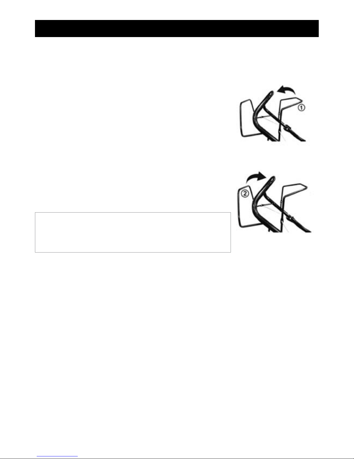
ASSEMBLY
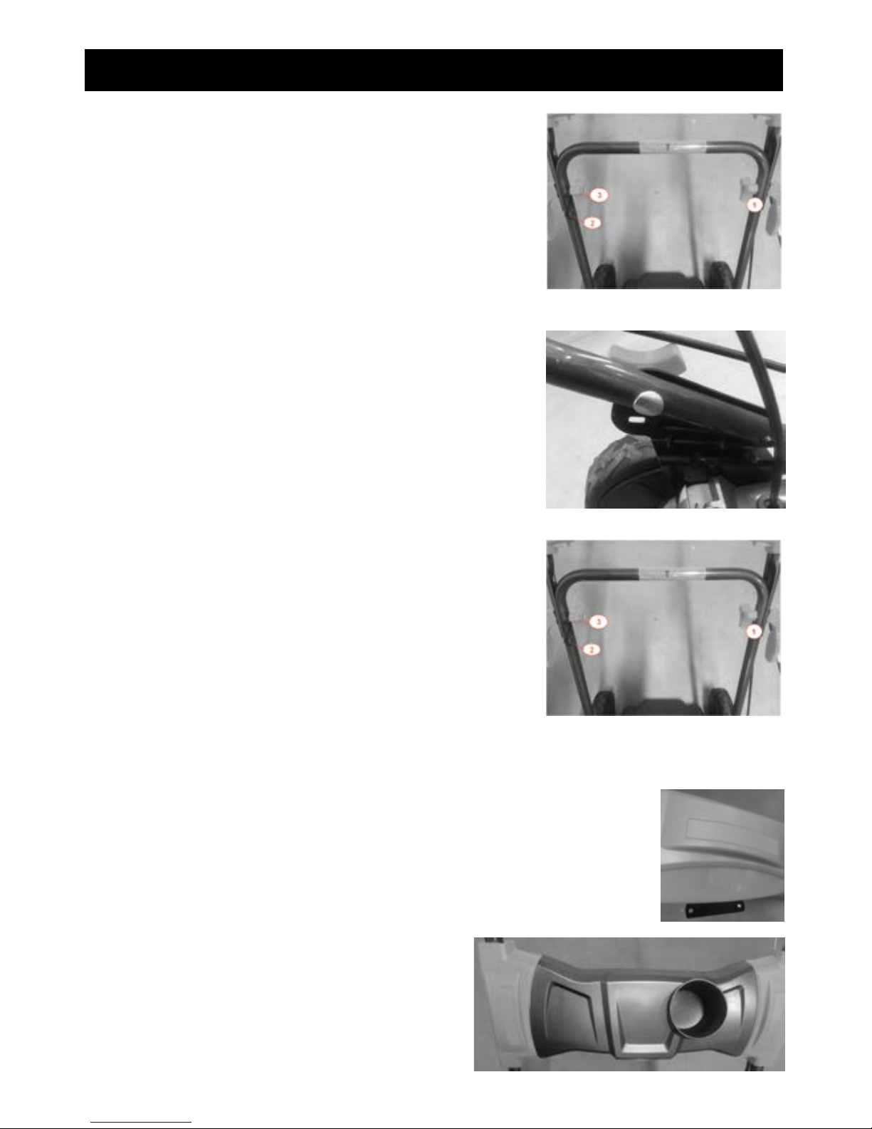
A. Lower Handle
»Place the holes of the lower bar on the support (1).
»Fix the bar with provided screws and wing nuts (2).
Note: The position of the bar can be adjusted.
»There are 3 positions (see right picture).
»Screw the screw and wing nut in the desired position.
B. Upper Handle
»Place the upper handle on the lower handle.
»On the left side, place the wing nut and the lock lever.
Screw them on in place. The lock lever must be in the same
direction as the bar (1).
»On the right side, install the hook on the wing nut (2). Then
install the wing nut and the lock lever and screw them into
place. The lock lever must be in the same direction as the
bar (3).
C. User Plate
»Insert the small plate in its dedicated location (both side).
»Install the user plate. Screw the plate in place with the
provided 4 screws provided (the holes are below the user
plate).
11
WWW.BBTA.COM.AUBBT-SP70
ASSEMBLY
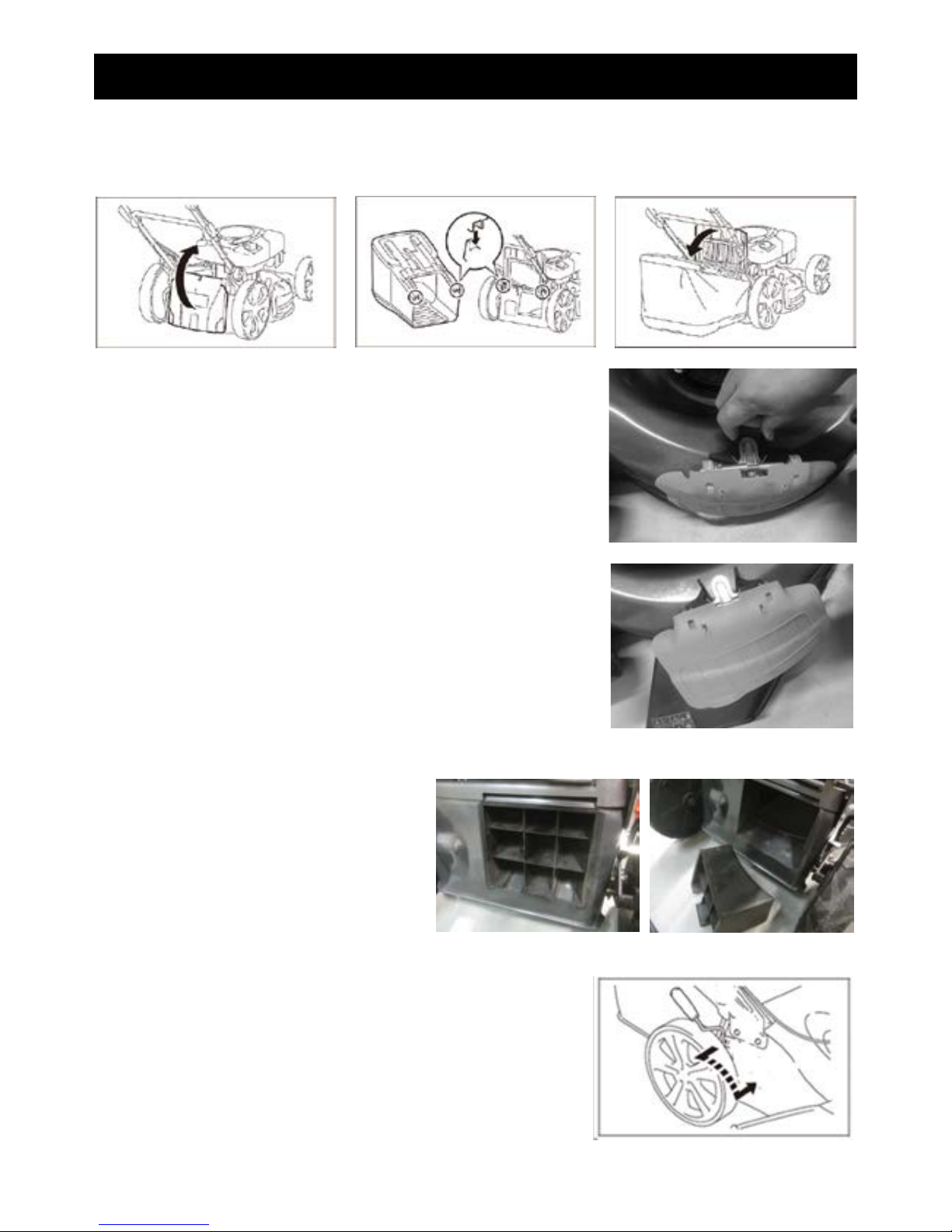
D. Mounting / Disassembling the Grass Catcher
»To install: Lift the flap and hook the grass catcher to the back of the mower.
»To remove it: hold the flap and lift it up, then remove the grass catcher.
E. Side Discharge
»Push the lock of the flap to lift it up.
»Hold the flap and place the side discharge.
NOTE: Before installing the side discharge, remove the grass catcher.
Both functions cannot be used together at the same time.
F. Assembly/Disassembly of the Mulching Plug
»Remove the grass catcher.
»Place the mulching plug into the rear
discharge chute. Make sure that both
pins are pressed down into the holes.
»Release the flap so that it will close back
to cover the mulching plug
G. Cutting Height Adjustment
»Push the lever outward to disengage it from the housing. Move
it forwards or backwards to adjust the height.
12
WWW.BBTA.COM.AU BBT-SP70
OIL AND FUEL FILLING
Fuel is extremely flammable.
• Store fuel only in cans specifically designed for this purpose.
• Fill the fuel tank only outdoors and before starting the engine. DO NOT smoke when filling the fuel
tank or handling fuel.
• NEVER open the fuel tank cap and never add fuel while the engine is running or when it is hot.
• If fuel is spilled, DO NOT start the engine, move the mower away from where the fuel has been spilled,
and be careful not to create a spark or flame until the fuel vapours have dissipated.
• Fully close fuel and oil tank correctly.
• Before tilting the mower to maintain the blade or drain the oil, empty the fuel tank.
• NEVER fill the fuel tank in and enclosed space or while the engine has cooled down for at least 15
minutes after use.
WARNING
DO NOT use unapproved fuel such as E10. DO NOT mix oil with petrol or modify the engine so that it runs
on alternative fuels. The use of unapproved fuels will damage the engine parts and will void the warranty.
CAUTION
• Always use clean, new, unleaded petrol with a minimum octane rating of 95/98.
Filling the Fuel Tank
Fuel must meet the following criteria:
Filling
• Remove the fuel tank cap.
• Close the fuel tank cap correctly after filling.
• Add fuel to the tank slowly.
• Wipe off any spilled fuel before starting the engine.
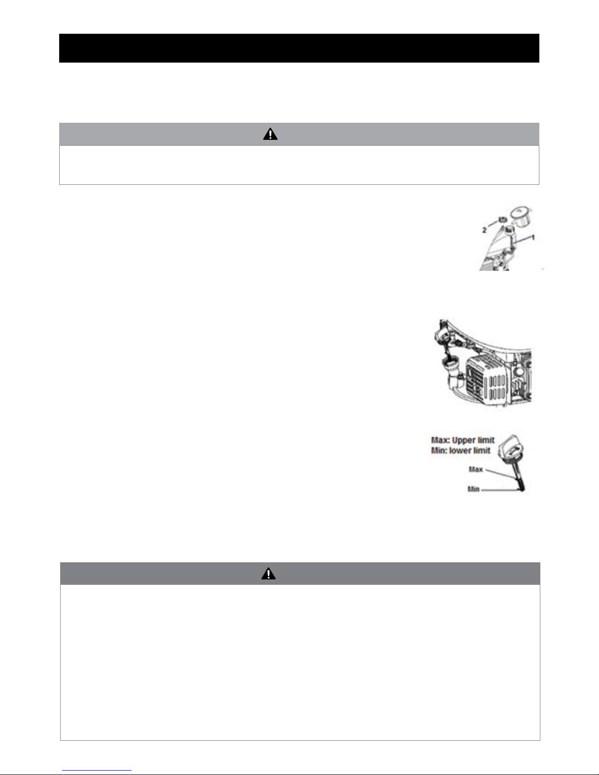
Oil Tank
Recommended Oil
• We recommend the use of high quality oil such as SAE 30 oil.
• DO NOT use special additives.
Filling
• Open the oil tank cap.
• Fill the tank with oil to the upper limit level on the dipstick.
• Close the oil tank.
Checking the Oil Level
• Check the oil level with the mower horizontal and the engine switched off and
cooled.
• Remove the plug / dipstick from the oil tank and wipe it off.
• Plug / dipstick into the tank neck as shown, without screwing it in, and then
remove it to check the oil level.
• If the oil level is near or below the lower limit on the dipstick, remove the plug
/ dipstick and fill the oil reservoir to the upper limit on the dipstick (bottom edge of the dipstick). DO NOT
overfill.
• Replace the oil tank plug / dipstick.
13
WWW.BBTA.COM.AUBBT-SP70
OPERATION
Before mowing, install the grass catcher in its intended position.
Start the device on safe and flat ground, preferably not in tall grass. Make sure that the cutting tools do not
touch objects or the ground.
Starting the Engine
• Pull the operator control lever towards the upper handle bar and hold it
together.
• Pull the recoil starter rope.
• If the engine starts, pull back slowly the recoil starter rope.
Stopping the Engine
• Release the operator control lever.
• The engine will stop and the blades will slow down.
• Wait until the blades stop completely before moving or storing.
Self-Propeller Function
• Pull the self-propeller bar towards the handle until it clicks.
• To stop the self-propelled mechanism, release the self-propeller bar.
• To stop the self-propelled mechanism and the machine, release both the
operator control lever and self-propeller bar.
Work Instructions
• Adjust the cutting height so that the machine is not overworked.
• Drive the machine at moderate speed (walking).
• DO NOT mow backwards.
• Always mow across slopes, not up and down.
• If the blades come into contact with a foreign object, immediately turn off the engine. Wait for the blades
to stop turning completely and check that the unit has not been damaged. Only resume work if the unit has
not been damaged.
• Turn off the mower when taking long breaks during work.
• Turn off the mower and wait for the blades to stop turning completely before moving or carrying the
machine.
• Clean your mower after each use as described in the section “Cleaning and Maintenance”.
NOTE: To stop the self-propelled without turning off the engine, release
the operator control lever a little until the self-propelled mechanism
disengages. Pull the operator control lever back towards the handle and
continue to mow without the self-propelled mechanism.
14
WWW.BBTA.COM.AU BBT-SP70
MAINTENANCE & STORAGE
• NEVER store the mower with the tank filled with fuel in a closed room where fuel vapours may come into
contact with a strong heat source or flame. Allow the engine to cool before storing your mower in its storage
area.
• To reduce the risk of fire, clean the mower, especially the engine, muffler and fuel tank. Remove all traces
of grass or leaves.
• Check the condition of the grass collection bag frequently. Replace if it is damaged.
• If you need to empty the oil tank, carry out this operation outdoors.
• Wear thick gloves before mounting or sharpening the blade. Make sure the blade is still well balanced.
• Regularly check the oil level and add or replace if necessary.
• Inspect the mower frequently and make sure all grass deposits are removed under the crankcase.
• Check the blade often. For a clean mow, the blade must always be sharpened and well balanced.
• At regular intervals, check that all bolts and screws are tight to keep the mower in a safe operating condition.
Worn or loose nuts and bolts can cause severe damage to the engine or crankcase.
• If the blade bangs or rattles violently, stop the mower and service.
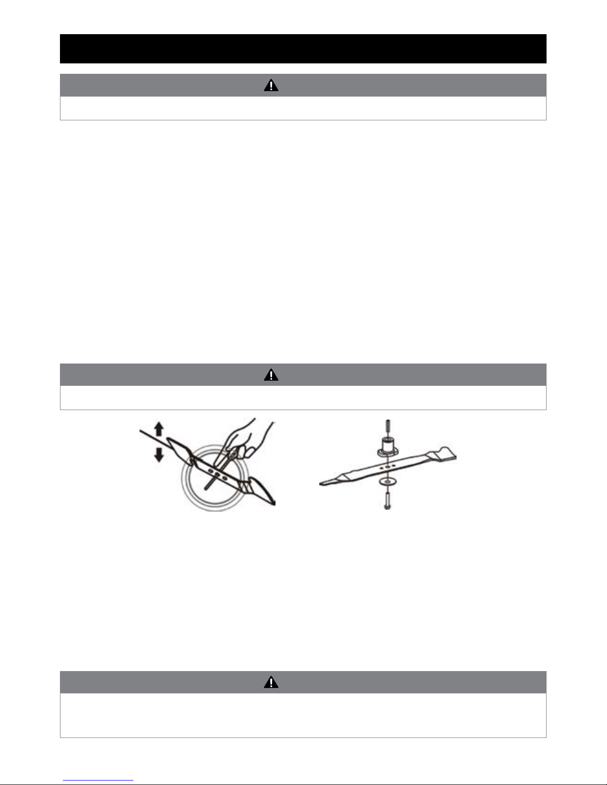
Blade
• The blade is made of hardened steel. For a clean mow, sharpen the blade frequently, approximately every 25
hours of use. Make sure the blade is always well balanced.
• Insert the small iron pin (2 or 3 mm in diameter) into the hole in the middle of the blade - the blade must
remain horizontal. If the blade does not remain horizontal, balance it by sharpening it further on the side
where it is leaning.
• To remove the blade, loosen the screw, check the blade bracket, and replace all parts if they are worn or
damaged.
• To sharpen the blade, place it in a clamp and file the sharp edges evenly, checking the balance of the blade.
• When reassembling the blade, make sure that the cutting edges are in the same direction as the direction of
rotation of the motor. The tightening torque of the blade screw should be 3.7 kg * m/s2(37 Nm) and can be
checked with a torque wrench.
Turn off the engine and remove the spark plug before servicing.
WARNING
Wear gloves, turn off the engine and remove the spark plug before proceeding.
WARNING
Use only original spare parts. Poor quality replacement parts can cause serious damage to your mower
and affect your safety. Contact our service agent to obtain specifications regarding the correct the correct
original spare parts.
WARNING

15
WWW.BBTA.COM.AUBBT-SP70
Spark Plug
• Check the spark plug after the first five hours of mower use. Thereafter, maintenance of the spark plug
should take place every 25 hours.
• Remove the spark plug cap using a rotary motion and then remove the spark plug with the wrench provided.
• Clean off any carbon deposits using a copper brush and check the electrode gap with a feeler gauge.
• Replace and retighten the serviced spark plug and replace the cap.
• If the spark plug is worn or damaged, replace with a new spark plug of the same or suitable type for the
engine.
Air Filter
• An air filter in poor condition will reduce the performance and life of the engine while making it harder to
start. Regular checks are therefore essential, especially when using the mower in dusty conditions. Check
and clean the air filter after every 25 hours of use, or more often if the engine is used in a dusty environment.
• Remove the air box lid and carefully remove the foam filter cartridge. Clean the cartridge in a small bowl of
warm water containing a few drops of dishwashing liquid until it is perfectly clean and free from all traces
of grease and dust. Rinse the filter cartridge in clean water and then squeeze gently to remove most of the
water. Let it air dry until it is completely dry.
• Clean the cover and inside of the air box with a clean lint-free cloth. Apply a uniform layer of oil to the
outside of the cartridge filter with a brush (you can use clean engine oil for this). Insert the filter cartridge
into its housing and replace the air box lid, ensuring that each component is in place and properly installed.
If the filter cartridge is damaged or is very dirty, replace it using a genuine part.
• The maintenance of a foam pre-filter is identical to that of a foam cartridge filter, as described above. The
cartridge filter paper should be cleaned with a vacuum cleaner. If it is dirty or contaminated with oil or
petrol, replace it.
Adjusting the Transmission Cable
• In its transmission-engaged position, the mower’s advance lever is pushed fully towards the handlebar. An
incorrectly-adjusted transmission cable can cause premature wear to the mower’s drive system.
• If the transmission cable is too tight, it will be difficult to move the advance lever towards the handlebars.
Conversely, if the transmission cable is not tight enough, the transmission will function poorly and will lack
power.
• To adjust the tension of the transmission cable, increase or reduce the length of the adjustment device using
the key. Check the effectiveness of the transmission and the resistance of the lever.
• When the correct adjustment has been reached, secure the adjustment device by tightening the lock nuts.
Storage
• Clean and maintain the mower (as explained above) before storage.
• The mower must be parked and stored in a safe location, out of humidity and away from flammable or
dangerous material.
• Store the mower out of reach of children.
MAINTENANCE & STORAGE
NEVER clean the foam cartridge in petrol, white spirit or other solvents. These products will degrade the
filter cartridge.
WARNING

16
WWW.BBTA.COM.AU BBT-SP70
SPECIFICATIONS
MODEL SP-70
Nominal power (kW) 2.8
Engine displacement (cm3) 163
Maximum rotational speed min¹ 2800
Cutting height (mm) 25-65
Cutting width (mm) 525
Volume of grass catcher (l) 60
Unit mass (kg) 38
Volume of fuel tank (l) 1.0
Volume of oil tank (l) 0.47
Measured sound pressure level 84.1 dB(A)
K = 3 dB(A)
Equivalent sound pressure level 89 dB(A)
kpA: 3 dB(A)
Measured sound power level 97.54 dB(A)
K = dB(A)
Guaranteed sound power level 98 dB(A)
Equivalent vibration value 6 m/s²
K = 1.5 m/s²
Technical Data is subject to change without notice.
Always wear hearing protection when operating your machine.
There is a risk of hearing loss if no hearing protection is worn.

17
WWW.BBTA.COM.AUBBT-SP70
WARRANTY & SERVICE
Warranties
Bigger Boyz Toyz offer a 1-year parts warranty on all products used for domestic use from the date of purchase.
For all commercial use, a 3-month parts warranty period applies, unless specified in the item listing. All conditions
below are based upon the product being faulty or not performing as described. In the instance where a return
is required, the purchaser is liable for any shipping cost. Warranties will only be determined by a Bigger Boyz
Toyz Technician upon inspection.
Warranties do not cover accidents, misuse, neglect, natural disaster or act of God or other external causes, or
damage caused by operating the equipment in a manner that is not described in the instructions.
Our products come with guarantees that cannot be excluded under the Australian Consumer Law. You are entitled
to a replacement or refund for a major failure and for compensation for any other reasonably foreseeable loss or
damage. You are also entitled to have the goods repaired or replaced if the goods fail to be of acceptable quality
and the failure does not amount to a major failure.
Parts purchases, consumable components and accessories such as chains, carry bags, batteries, hoses, grinding
discs, covers, belts, cable, wheels and blades are not covered by standard warranty.
Spare Parts
Spare parts are available. Please see our website (www.bbta.com.au) or contact us at bbt@bbta.com.au for more
details.

18
WWW.BBTA.COM.AU BBT-SP70
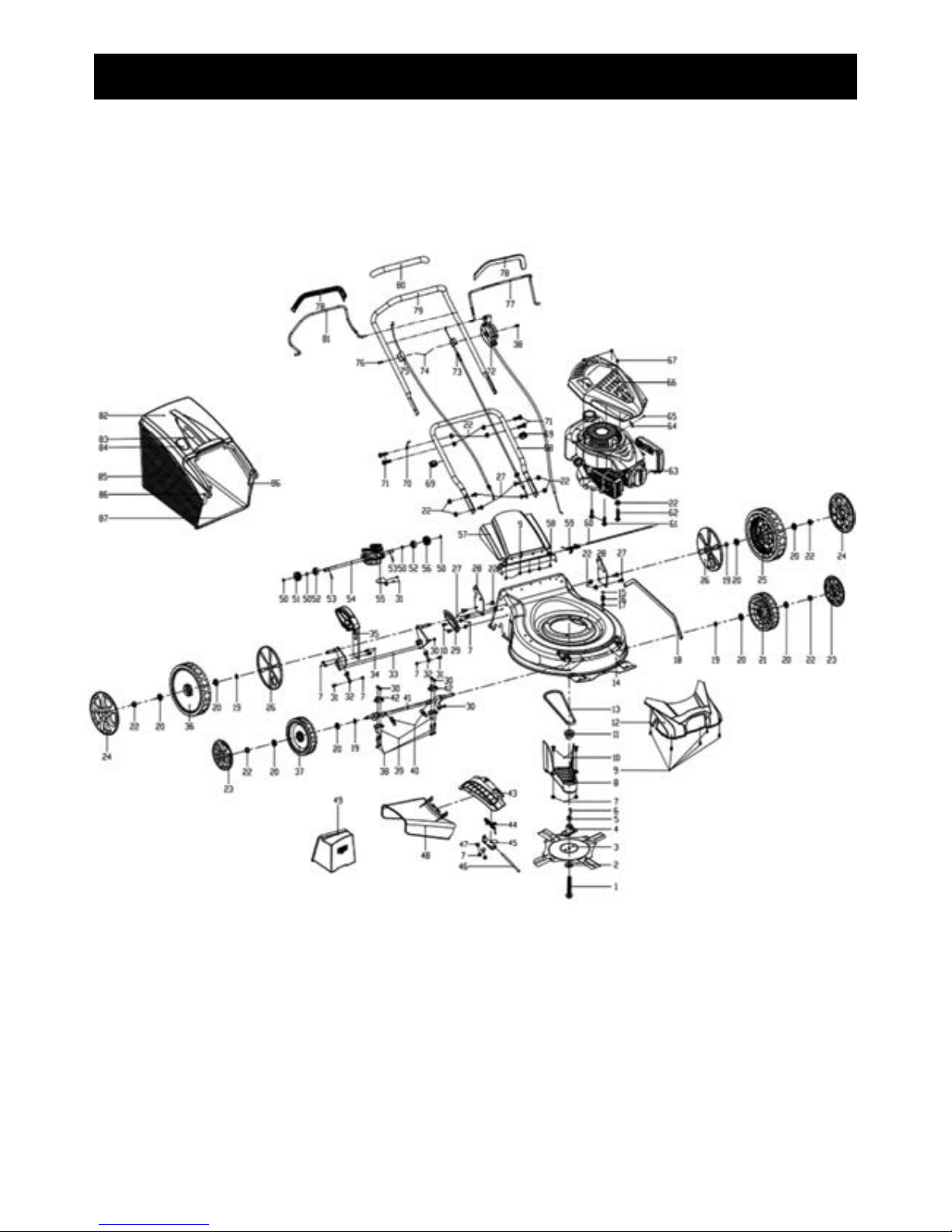
EXPLODED DIAGRAM & PARTS LIST
NOTE: Due to continuous product improvement, we reserve the right to
change the product without prior notice.
NO SKU DESCRIPTION QTY
1SP-SP70-001 Blade bolt 1
2SP-SP70-002 Butterfly type washer 1
3SP-SP70-003 Swing blade 1
4SP-SP70-004 Blade holder 1
5SP-SP70-005 Washer 1
6SP-SP70-006 Crankshaft key 1
7SP-SP70-007 Nut 8
8SP-SP70-008 Belt cover 1
9SP-SP70-009 Self-tapping screw 10
10 SP-SP70-010 Square neck bolt 4
11 SP-SP70-011 Driving belt wheel 1
12 SP-SP70-012 Self-propelled assembly 1
13 SP-SP70-013 Belt 1
14 SP-SP70-014 Deck 1
15 SP-SP70-015 O-ring 1
16 SP-SP70-016 Bracket of front wheel axle 1
17 SP-SP70-017 Nut 1
18 SP-SP70-018 Collection rod 1
19 SP-SP70-019 Washer 4
20 SP-SP70-020 Bearing 8
21 SP-SP70-021 7.5" wheel(L) 1
22 SP-SP70-022 Nut 17
23 SP-SP70-023 7.5" wheel cover 2
24 SP-SP70-024 10.5" wheel cover 2
25 SP-SP70-025 10.5" wheel(L) 1
26 SP-SP70-026 Inner wheel cover 2
27 SP-SP70-027 Square neck bolt 8
28 SP-SP70-028 Left handle rail bracket 2
29 SP-SP70-029 Adjustment height board 1
30 SP-SP70-030 Nut 6
31 SP-SP70-031 Hexagon flange bolts 4
32 SP-SP70-032 Fixed plate 2
33 SP-SP70-033 Rear wheel axle 1
34 SP-SP70-034 Hexagon flange bolts 4
35 SP-SP70-035 Self-propelled assembly 1
36 SP-SP70-036 10.5" wheel( R) 1
37 SP-SP70-037 7.5" w he el ( R ) 1
38 SP-SP70-038 Hexagon flange bolts 5
39 SP-SP70-039 Bracket of front wheel axle 2
40 SP-SP70-040 Draw spring 2
41 SP-SP70-041 Front axle 1
42 SP-SP70-042 Bracket of front wheel axle 2
43 SP-SP70-043 Seal board 1
44 SP-SP70-044 Torsional spring 1
NO SKU DESCRIPTION QTY
45 SP-SP70-045 Bracket 1
46 SP-SP70-046 Round rod 1
47 SP-SP70-047 Square neck bolt 2
48 SP-SP70-048 Side discharge 1
49 SP-SP70-049 Plug 1
50 SP-SP70-050 Shaft ring 4
51 SP-SP70-051 Gear assembly 1
52 SP-SP70-052 Bearing (R8RS) 2
53 SP-SP70-053 Pin 2
54 SP-SP70-054 Self-propelled assembly 1
55 SP-SP70-055 Plate 1
56 SP-SP70-056 Gear assembly 1
57 SP-SP70-057 Rear discharge cover 1
58 SP-SP70-058 Dust-proof board 1
59 SP-SP70-059 Torsional spring 1
60 SP-SP70-060 Round rod 1
61 SP-SP70-061 Hexagon flange bolts 2
62 SP-SP70-062 Hexagon flange bolts 1
63 SP-SP70-063 Engine 1
64 SP-SP70-064 Plate 1
65 SP-SP70-065 Cross recessed pan head screw 1
66 SP-SP70-066 Plastic cover 1
67 SP-SP70-067 Nut 2
68 SP-SP70-068 Lower handrail 1
69 SP-SP70-069 Cable clip 2
70 SP-SP70-070 Hook 1
71 SP-SP70-071 Hexagon flange bolts 4
72 SP-SP70-072 Throttle control cable assembly 1
73 SP-SP70-073 Driving cable assembly 1
74 SP-SP70-074 Nut 2
75 SP-SP70-075 Brake cable assembly 1
76 SP-SP70-076 Hexagon flange bolts 1
77 SP-SP70-077 Brake lever 1
78 SP-SP70-078 Axle sleeve 2
79 SP-SP70-079 Upper handrail 1
80 SP-SP70-080 Cable tube 1
81 SP-SP70-081 Driving rod 1
82 SP-SP70-082 Top cover of grass bag 1
83 SP-SP70-083 Cover 1
84 SP-SP70-084 Indicator 1
85 SP-SP70-085 Half plastic box 1
86 SP-SP70-086 Self-tapping screw 2
87 SP-SP70-087 Collection bag frame 1
Component Parts Diagram
19
WWW.BBTA.COM.AUBBT-SP70
EXPLODED DIAGRAM & PARTS LIST

20
WWW.BBTA.COM.AU BBT-SP70
EXPLODED DIAGRAM & PARTS LIST
NO SKU DESCRIPTION
1 SP-SP70ENG -001 Nut
2 SP-SP70 ENG-002 Muffler cover
3 SP-SP70ENG -003 Muffler assembly
4 SP-SP70ENG -004 Heat insulation gasket of muffler
5 SP-SP70ENG -005 Spark plug
6 SP-SP70ENG -006 Hexagon flange bolts
7 SP-SP70ENG -007 Scald-proof cover
8 SP-SP70 ENG-008 Cylinder head cover
9 SP-SP70ENG -009 Gasket of cylinder cover
10 SP-SP70 ENG-010 Nut
11 SP-SP70ENG-011 Nut
12 SP-SP70ENG-012 Valve rocker
13 SP-SP70 ENG-013 Adjustment bolt
14 SP-SP70 ENG-014 Spring socket
15 SP-SP70 ENG-015 Hood
16 SP-SP70 ENG-016 Valve spring keepers
17 SP-SP70 ENG-017 Spring
18 SP-SP70 ENG-018 Push rod assembly
19 SP-SP70 ENG-019 Push rod assembly
20 SP-SP70 ENG-020 Hexagon flange bolts
21 SP-SP70 ENG-021 Double head bolt
22 SP-SP70 ENG-022 Cylinder head
23 SP-SP70 ENG-023 Intake valve
24 SP-SP70 ENG-024 Exhaust valve
25 SP-SP70 ENG-025 Pin
26 SP-SP70 ENG-026 Gasket of cylinder head
27 SP-SP70 ENG-027 Gasket I of air inlet pipe
28 SP-SP70 ENG-028 Air inlet pipe
29 SP-SP70 ENG-029 Carburettor insulation pad
30 SP-SP70 ENG-030 Gasket of air filter
31 SP-SP70 ENG-031 Carburettor assembly
32 SP-SP70 ENG-032 Gasket of air filter
33 SP-SP70 ENG-033 Bracket of air filter
34 SP-SP70 ENG-034 Air director bush
35 SP-SP70 ENG-035 Nut
36 SP-SP70 ENG-036 Paper filter element assembly
37 SP-SP70 ENG-037 Foam filter element
38 SP-SP70 ENG-038 Upper cover
39 SP-SP70 ENG-039 Piston ring
40 SP-SP70 ENG-0340 Jump ring
41 SP-SP70 ENG-041 Connect rod assembly
42 SP-SP70 ENG-042 Piston
43 SP-SP70 ENG-043 Pin
44 SP-SP70 ENG-044 Hexagon flange bolts
45 SP-SP70 ENG-045 Oil ruler assembly
46 SP-SP70 ENG-046 Refuelling device spacer
47 SP-SP70 ENG-047 Rubber washer
48 SP-SP70 ENG-048 Bolt
49 SP-SP70 ENG-049 Washer
50 SP-SP70 ENG-050 Oil seal
51 SP-SP70-ENG-051 Box cover
52 SP-SP70 ENG-052 Washer
53 SP-SP70 ENG-053 Gear shaft
54 SP-SP70 ENG-054 Speed regulator gear assembly
55 SP-SP70 ENG-055 Washer
NO SKU DESCRIPTION
56 SP-SP70 ENG-056 Sleeve
57 SP-SP70 ENG-057 Pressing plate
58 SP-SP70 ENG-058 Hexagon flange bolts
59 SP-SP70 ENG-059 Camshaft
60 SP-SP70 ENG-060 Pin
61 SP-SP70 ENG-061 Gasket of cylinder
62 SP-SP70 ENG-062 Pin
63 SP-SP70 ENG-063 Washer
64 SP-SP70 ENG-064 Crankshaft assembly
65 SP-SP70 ENG-065 Freather pipe
66 SP-SP70 ENG-066 Roller bearing
67 SP-SP70 ENG-067 Crankcase
68 SP-SP70 ENG-068 Fixed clip
69 SP-SP70 ENG-069 Fixed plate
70 SP-SP70 ENG-070 Draw spring
71 SP-SP70 ENG-071 Speed regulator rod
72 SP-SP70 ENG-072 Oil seal
73 SP-SP70 ENG-073 Split pin
74 SP-SP70 ENG-074 Draw spring
75 SP-SP70 ENG-075 Handspike of valve
76 SP-SP70 ENG-076 Screw
77 SP-SP70 ENG-077 Speed regulator rocker
78 SP-SP70 ENG-078 Twisting clip B
79 SP-SP70 ENG-079 Fuel inlet pipe
80 SP-SP70 ENG-080 Twisting clip A
81 SP-SP70 ENG-081 Fuel filter net
82 SP-SP70 ENG-082 Fuel tank
83 SP-SP70 ENG-083 Seal gasket of fuel tank cap
84 SP-SP70 ENG-084 Foam
85 SP-SP70 ENG-085 Fuel tank cap
86 SP-SP70 ENG-086 Fuel tank bracket (left)
87 SP-SP70 ENG-087 Tank bracket
88 SP-SP70 ENG-088 Fuel tank bracket (right)
89 SP-SP70 ENG-089 Filter net
90 SP-SP70 ENG-090 Valve element
91 SP-SP70 ENG-091 Gasket of respirator
92 SP-SP70 ENG-092 Respirator cover plate
93 SP-SP70 ENG-093 Double head bolt
94 SP-SP70 ENG-094 Air director bush
95 SP-SP70 ENG-095 Oil seal
96 SP-SP70 ENG-096 Flying wheel
97 SP-SP70 ENG-097 Fan
98 SP-SP70 ENG-098 Drived disk
99 SP-SP70 ENG-099 Nut
100 SP-SP70 ENG-100 Wind scooper
101 SP-SP70 ENG-101 Start assembly
102 SP-SP70 ENG-102 Governor bush
103 SP-SP70 ENG-103 Detent
104 SP-SP70 ENG-104 Hexagon flange bolts
105 SP-SP70 ENG-105 Ignition switch assembly
106 SP-SP70 ENG-106 Hexagon flange bolts
107 SP-SP70 ENG-107 Flameout line assembly
108 SP-SP70 ENG-108 Air director bush III
109 SP-SP70 ENG-109 Ignition assembly
110 SP-SP70 ENG-110 Double head bolt
Engine Parts Diagram
Table of contents
Other BBT Lawn Mower manuals


