BCA LEISURE PDU MK II User manual

PDU MK II
MANUFACTURERS
INSTALLATION AND USER GUIDE
V2
BCA LEISURE LTD

Table of Contents
Description of product……………………………1
Installation of the PDU……………………………1
Access to the connectors…………………………2
Connection to the mains supply………………..2
Ventilation……………………………………………3
Storage………………………………………………..4
Servicing………………………………………………4
PCB Pin information……………………………….5
Description of Product
PDU (Power Distribution Unit)
230V: The PDU is designed to distribute 230Vac to appliances and
sockets throughout the habitation area of the caravan or motor home
via suitable protection devices.
The circuits are designed to customer specifications.
12V: The PDU is designed to distribute the 12Vdc power throughout
the habitation area of the caravan and motor home via relays and
fused circuits.
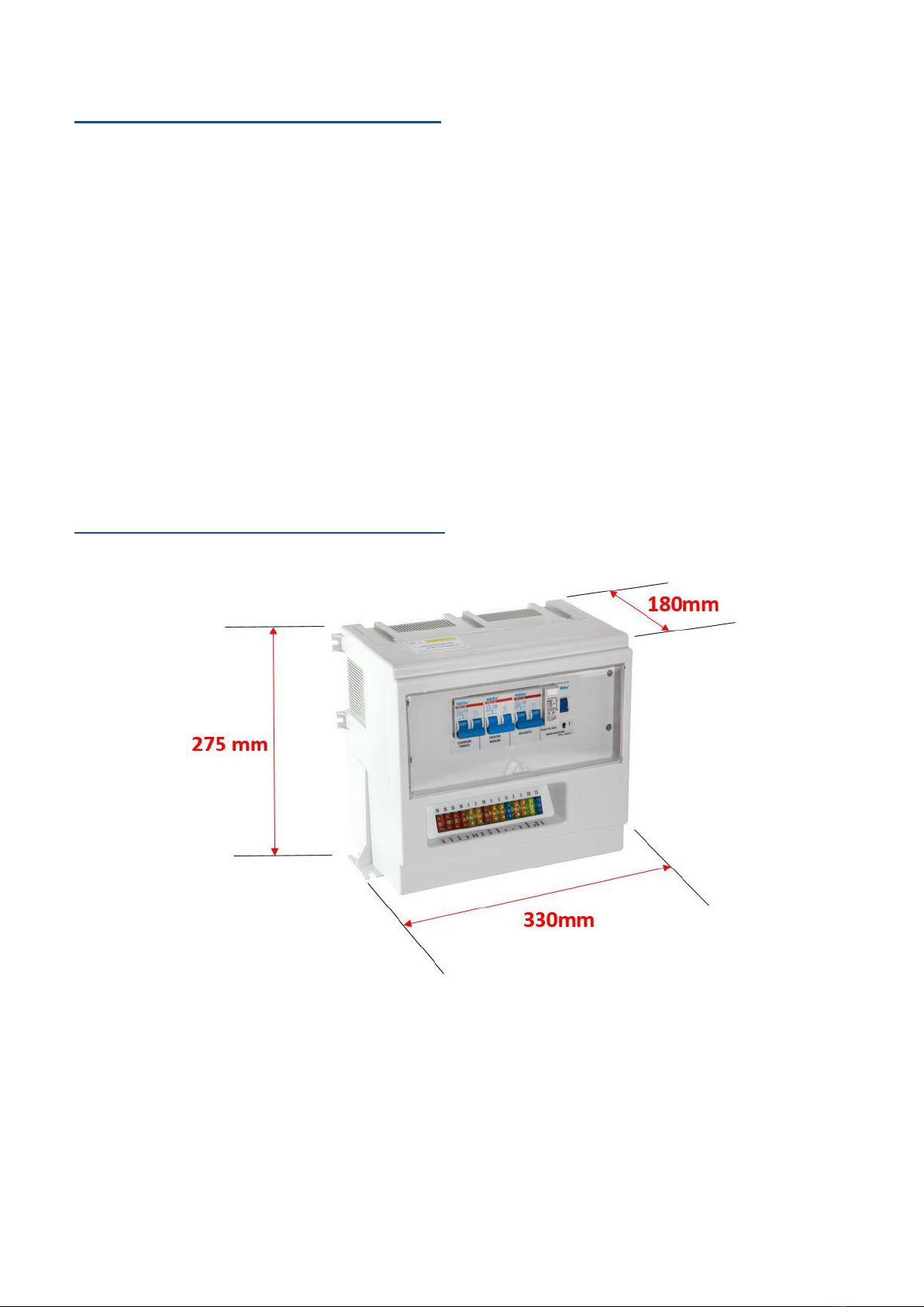
Installation of the PDU
Dimensions of the PDU.
Ventilation
The PDU requires a minimum surrounding clearance of 75mm around the
ventilation slots.
The PDU MUST be installed as such that external heat sources will not have a
detrimental effect on the normal operation of the unit.
Fig 1
A
A
B
B
Fig 2
Fig 3
A
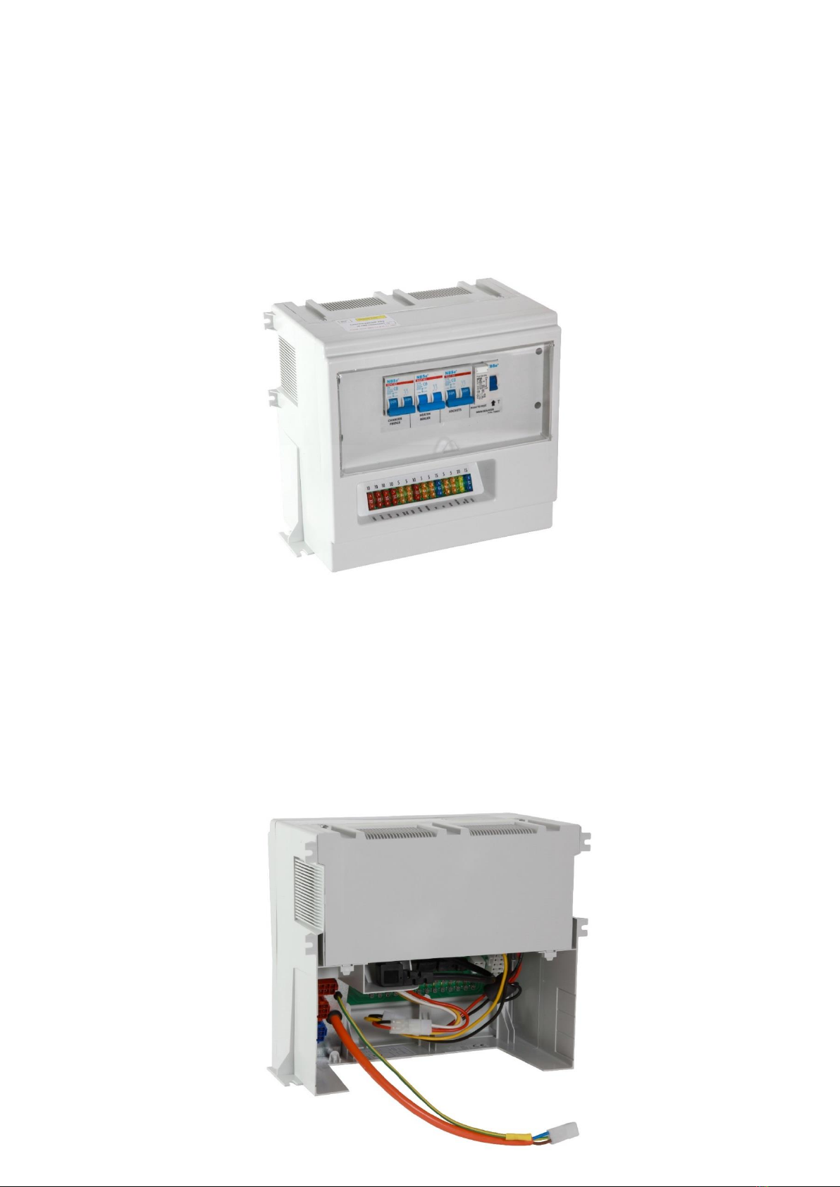
Fixing of the PDU to a vertical or horizontal surface.
The PDU can be fixed to either a vertical or horizontal surface using
the fixing lugs located on the PDU (Fig 1 points A+B).
All four fixing points of A or B MUST be used to secure the PDU to
prevent damage to the unit from vibration.
The fixing lugs are mirrored on the opposite side of the PDU.
Access to connectors
The PDU should be installed in such a way that access to the
connectors at the rear of the PDU (Fig 3) are only accessible by the
use of a tool either by location or an enclosure securely fastened
behind the PDU.

Connection to the mains supply
Connection of the PDU to the mains supply* should be made by the
supplied connector (Fig 3 point A) enclosed in a suitable enclosure
accessible with use of a tool or by location accessible with the use of
a tool, connection can also be made by hard wiring to the supply
inlet**.
* Ensure the mains supply is switched off before connecting the PDU to the
mains
** Note all electrical work must be carried out by a competent person.
Storage of the PDU
The PDU MUST be stored in a dry storage area suitable for storing
electrical and electronic equipment.
Servicing of the PDU
The RCD and MCB’s should be checked at the annual service for
loose connections on the conductors and busbars.
The earth terminal should be checked at the annual service for loose
connections.
The fixing lugs on the casing should be checked for loose fixings and
damage at the annual service.
The 12V fuses should be checked for correct installation at the
annual service.

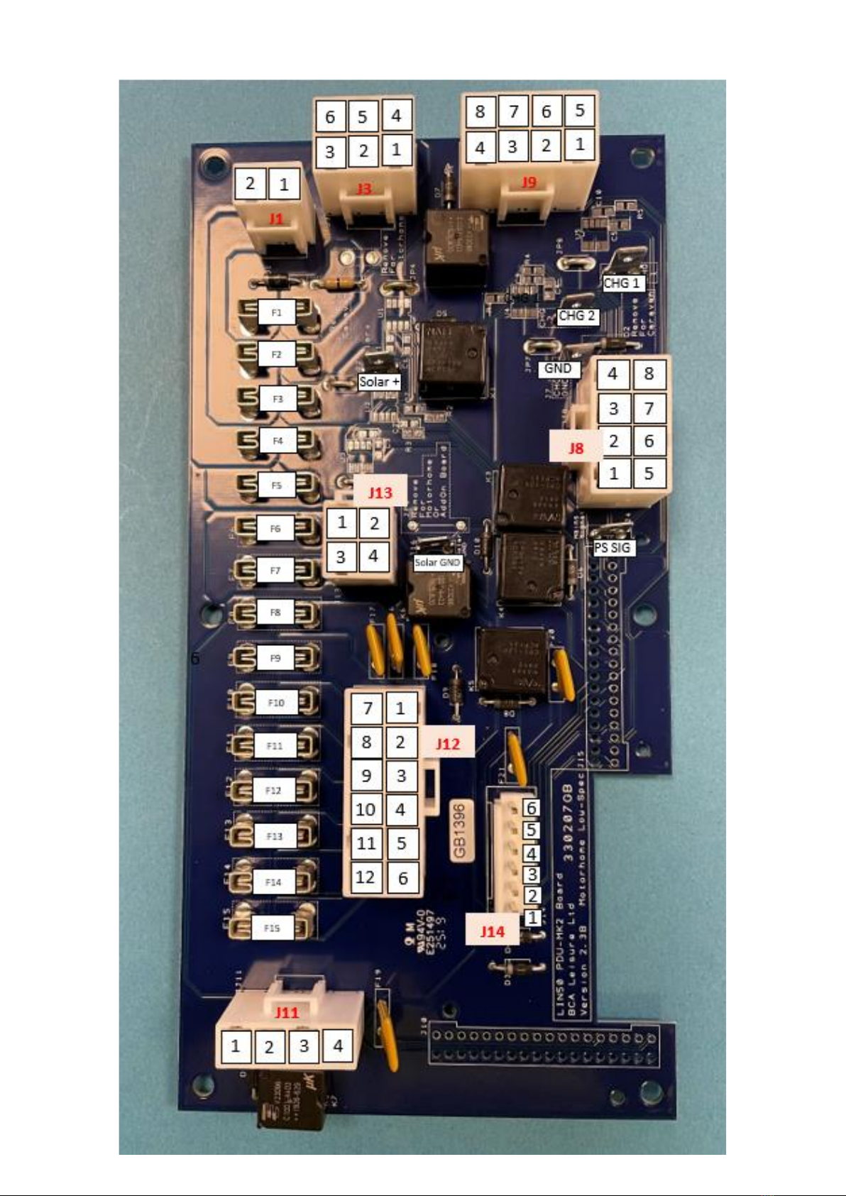
PCB Pin information
Currently there are two available PCB versions that can be installed
into the PDU unit, one has been designed for the use in caravans and
one has been designed for use in motorhomes.
PCB-268-MD (designed specifically for caravans)


PCB-269-MD (designed specifically for motor homes)

d
Lin50 PDU-MK2 V2.3

LIN50 PDU-MK2 BOARD V2.3B
Plug
Ident
Pin
Number
Circuit
Fuse
Max Rated
fuse
J1
1
Negative from the leisure battery
J1
2
Positive from leisure battery
F2
25Amp
J3
1
Negative from the Vehicle battery
J3
2
Negative from the Vehicle battery
J3
3
Ground linked to J8,1 + J9,1
J3
4
Positive from Vehicle battery
F4
25Amp
J3
5
Positive from Vehicle battery
F4
25Amp
J3
6
Ignition Feed
F1
20Amp
J8
1
Negative linked to J3,3
J8
2-8
Negative Outputs
J9
1
Negative linked to J3,3
J9
2-8
Negative Outputs
J11
1
Independent relay "N/O" (typically used as a pump relay)
J11
2
Independent relay "common" (typically used as a pump relay)
J11
3
Independent relay "N/C" (typically used as a pump relay)
J11
4
Independent relay "coil" (typically used as a pump relay)
J12
1+2+7
Master switch-controlled Circuit
F9
20Amp
J12
3
Master switch-controlled Circuit!
F8+F18
5Amp
J12
4
Master switch-controlled Circuit
F13
20Amp
J12
5
Master switch-controlled Circuit!
F8+F16
5Amp
J12
6
Permanent feed
F15
5Amp
J12
8
Fridge Feed Out (live only when the engine is running)
F10
20Amp
J12
9
Master switch-controlled Circuit
F11
20Amp
J12
10
Master switch-controlled Circuit
F12
20Amp
J12
11
Master switch-controlled Circuit!
F8+F17
5Amp
J12
12
Permanent feed
F14
5Amp
J13
1+3
Lights out (Master switched controlled and lights relay controlled)*
F6
10Amp
J13
2+4
Lights out (Master switched controlled and lights relay controlled)*
F7
10Amp
J14
1
Permanent feed (Control Panel)
F5
5Amp
J14
2
Ignition Controlled Feed**(Control Panel )!
F20
5Amp
J14
3
Master Switch Return
J14
4
Lights Switch Return
J14
5
Leisure/Vehicle Select return
J14
6
Ignition Signal out!
F21
2.5Amp
J8
12
GRD
Negative from the power supply
CHG 1
Positive from the power supply*****
CHG 2
Positive from the power supply*****
PS SIG
Mains on signal from the power supply (selected models only) ****
Solar +
Permanent Circuit, can be used to connect a solar panel
F3
15A
Solar -
Return for solar +
*
Pins J4'1,2,3,4 Are outputs from a N/C relay which is controlled by the return to pin J14'4.
**
This circuit disconnected when the engine is running but is otherwise permanent.

****
when a positive feed is applied to this pin from the 12v ps sig when connected to mains it allows the
vehicle battery to be charged from the power supply.
*****
When using a dual stage power supply, the charging side must be fitted to CHG 1 and the power supply
output to CHG 2, when using a single stage power supply, the two tabs must be linked.
!
These fuses are non-replaceable, to reset disconnect power if the fault has been cleared
Table of contents


