BCE FlexStation Venus Overhead User manual

WZ-CrnrOverhead
Note:
Note:
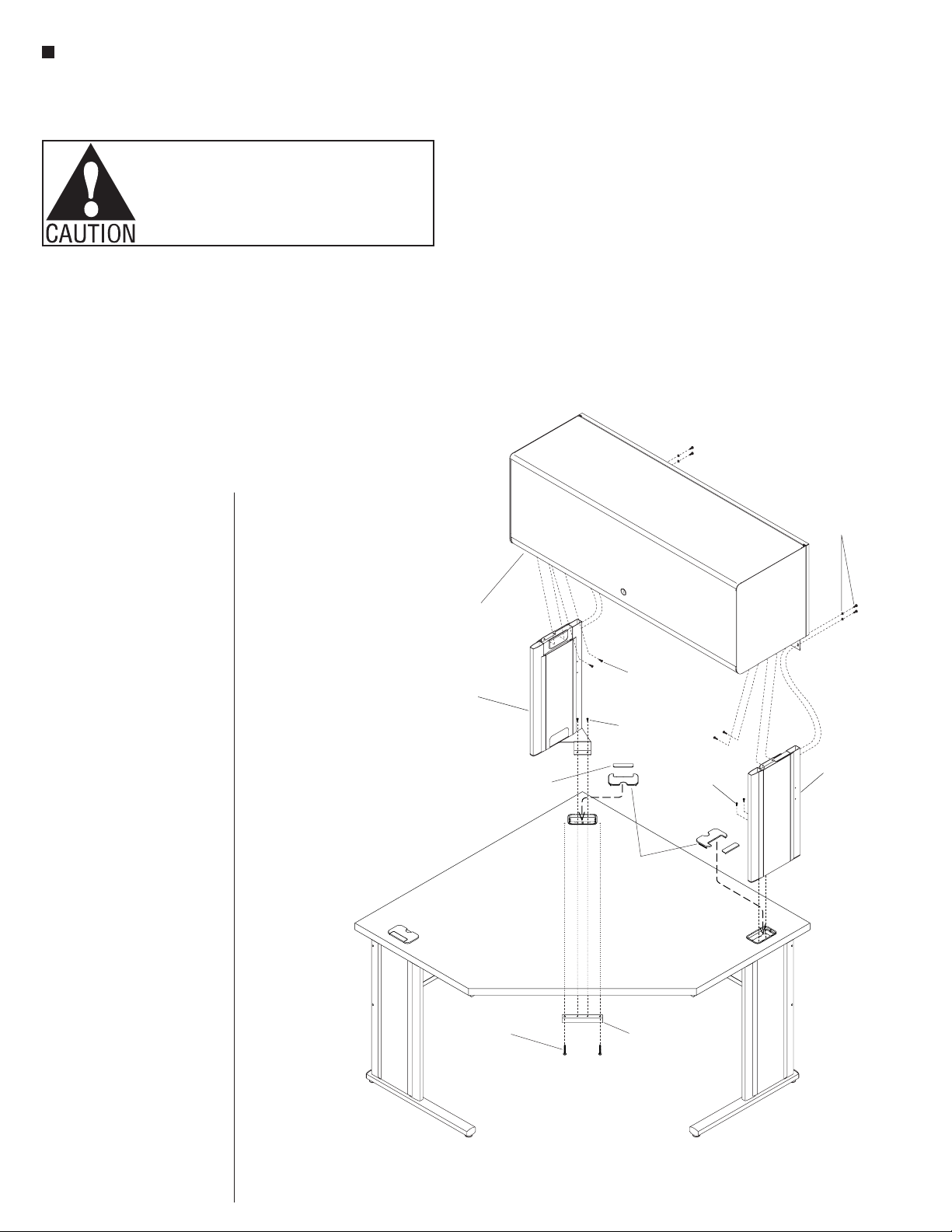
Determineif cabinet to be installed is
to be right-hand or left. Thisinstruction
covers right,thoughleft-hand cabinet
installationissimilar,itwillhaveadifferent
set of overhead stanchions.
WorkZone CornerDesk must be fully
installed priortoinstallingthe overhead unit.
1. Beginbyremoving grommet coversat
the rear corner,and side location wherethe
overhead cabinet will be installed (Figure1).
2. At therear corner, from underneath the
corner worksurface, installacorner
overhead mountingtubeusing two #12x
1-3/4” screws (Figure1).
3. Positionthe corner stanchion (left-hand)
as illustratedthrough the corner grommet
hole, aligning the mountingholes in the
bracket of thestanchion with the mounting
holes of the corner overhead mountingtube.
Secure bracket to tubeusing two #10-32 x
1/2” screws (Figure1).
4. Positionthe right-hand stanchion with the
bracket through the grommet hole, aligning
the mountingholes in the bracket of the
stanchion with the mountingholes in thetop
of the right-hand leg. Secure bracket to leg
using two #10-32x1/2” screws (Figure1).
5. Carefully set the Balance Overhead
Cabinet ontothe twoinstalledstanchions.
Alignthe three setsof mountingholes on
each sideof cabinet/stanchion and secure
using three #10x3/4” screws each side
(Figure1).
6. Remove theknock-outsfrom the
grommet covers removed in step 1, and
snap them back into place in the grommet
holes at thestanchions (Figure2).
WorkZone Corner Desk with Balance Overhead Cabinet
grommet
covers
grommet
knock-out
grommet
knock-out
Venus
overhead cabinet
corner
stanchion
corner overhead
mounting tube
#12x1/”
screw
34
right-hand
stanchion
#10-32 x½”
screw
#10x /”
screw
34
#10-32 x1”
screw
Figure1
Note: Determine if cabinet to be
installed is to be right-hand or left.
This instruction covers right, though
left-hand cabinet installation is similar,
it will have a different set of overhead
stanchions.
Note: FlexStation Corner Desk must be
fully assembled prior to installing the
overhead unit.
1. Begin by removing grommet covers
at the rear corner, and side location
where the overhead cabinet will be
installed (Figure 1).
2. At the rear corner, from underneath
the corner worksurface, install a
corner overhead mounting tube
using two #12 x 13/4” screws
(Figure 1).
3. Position the corner stanchion (left-
hand) as illustrated through the
corner grommet hole, aligning the
mounting holes in the bracket of the
stanchion with the mounting holes
of the corner overhead mounting
tube. Secure bracket to tube using
two #10-32 x 1/2” screws (Figure 1).
4. Position the right-hand stanchion
with the bracket through the
grommet hole, aligning the
mounting holes in the bracket of
the stanchion with the mounting
holes in the top of the right-hand
leg. Secure bracket to leg using two
#10-32 x 1/2” screws (Figure 1).
5. Carefully set the Venus Overhead
Cabinet onto the two installed
stanchions. Align the three sets of
mounting holes on each side of
cabinet/stanchion and secure using
three #10 x 3/4” screws each side
(Figure 1).
6. Remove the knock-outs from
the grommet covers removed in
step 1, and snap them back into
place in the grommet holes at the
stanchions (Figure 2).
Assembly Instructions
FlexStation Corner Desk Overhead Cabinet
Venus Overhead
OE-60931/PDF0314
Assemble units as described herein only. To do otherwise
may result in instability. All screws, nuts and bolts must be
tightened securely and must be checked periodically after
assembly. Failure to assemble properly, or to secure parts
may result in assembly failure and personal injury.
2
FlexStation®Corner Desk - Universal Overhead Cabinet
Assembly Instructions
Assemble units as described herein only. To do otherwise
may result in instability. All screws, nuts and bolts must be
tightened securely and must be checked periodically after
assembly. Failure to assemble properly, or to secure parts
may result in assembly failure and personal injury.
WorkZone Corner Desk with Universal Overhead Cabinet
corner overhead
mounting tube
#12x1/”
screw
34
#10-32x½” screw
& tooth washer
grommet
covers
grommet
knock-out
Universal
overhead cabinet
right-hand
stanchion
#10-32x½”
screw
#8-32x½”
screw
corner
stanchion
(left-hand)
#10-32 x
screw
½”
Note:
Note:
Determine if cabinet to be installed is
to be right-hand or left. This instruction
covers right, though left-hand cabinet
installation is similar,it will haveadifferent
set of overhead stanchions.
WorkZone Corner Desk must be fully
installed prior to installing the overhead unit.
1. Begin by removing grommet covers at
the rear corner, and side location where the
overhead cabinet will be installed (Figure 2).
2. At the rear corner, from underneath the
corner worksurface, installacorner
overhead mounting tube using two #12 x
1-3/4” screws (Figure 2).
3. Position the corner stanchion (left-hand)
as illustrated through the corner grommet
hole, aligning the mounting holes in the
bracket of the stanchion with the mounting
holes of the corner overhead mounting tube.
Secure bracket to tube using two #10-32 x
1/2” screws (Figure 2).
4. Position the right-hand stanchion with the
bracket through the grommet hole, aligning
the mounting holes in the bracket of the
stanchion with the mounting holes in the top
of the right-hand leg. Secure bracket to leg
using two #10-32x1/2” screws (Figure 2).
5. Carefully set the Universal Overhead
Cabinet onto the two installed stanchions.
Align the two sets of mounting holes on
each side of the cabinet/stanchion at the
rear and secure using two #10-32 x
½”screws and tooth washers at each side
(Figure 2).
6. At the underside of the cabinet, and the
inside top of each stanchion, secure the
stanchion top to the cabinet bottom using
two #8-32x½”screws at each side
(Figure 2).
7. Remove the knock-outs from the
grommet covers removed in step 1, and
snap them back into place in the grommet
holes at the stanchions (Figure 2)
Figure 2
Note: Determine if cabinet to be
installed is to be right-hand or left.
This instruction covers right, though
left-hand cabinet installation is
similar, it will have a different set of
overhead stanchions.
Note: FlexStation Corner Desk must
be fully assembled prior to installing
the overhead unit.
1. Begin by removing grommet
covers at the rear corner,
and side location where the
overhead cabinet will be
installed (Figure 2).
2. At the rear corner, from
underneath the corner
worksurface, install a corner
overhead mounting tube
using two #12 x 13/4” screws
(Figure 2).
3. Position the corner stanchion
(left-hand) as illustrated through
the corner grommet hole,
aligning the mounting holes
in the bracket of the stanchion
with the mounting holes of
the corner overhead mounting
tube. Secure bracket to tube
using two #10-32 x 1/2” screws
(Figure 2).
4. Position the right-hand
stanchion with the bracket
through the grommet hole,
aligning the mounting holes
in the bracket of the stanchion
with the mounting holes in
the top of the right-hand leg.
Secure bracket to leg using two
#10-32 x 1/2” screws (Figure 2).
5. Carefully set the Universal
Overhead Cabinet onto the two
installed stanchions. Align the
two sets of mounting holes
on each side of the cabinet/
stanchion at the rear and secure
using two #10-32 x ½” screws
and tooth washers at each side
(Figure 2).
6. At the underside of the cabinet,
and the inside top of each
stanchion, secure the stanchion
top to the cabinet bottom using
two #8-32 x ½” screws at each
side (Figure 2).
7. Remove the knock-outs from
the grommet covers removed in
step 1, and snap them back into
place in the grommet holes at
the stanchions (Figure 2).
Universal Overhead Cabinet
Assembly Instructions
Assemble units as described herein only. To do otherwise
may result in instability. All screws, nuts and bolts must be
tightened securely and must be checked periodically after
assembly. Failure to assemble properly, or to secure parts
may result in assembly failure and personal injury.
3
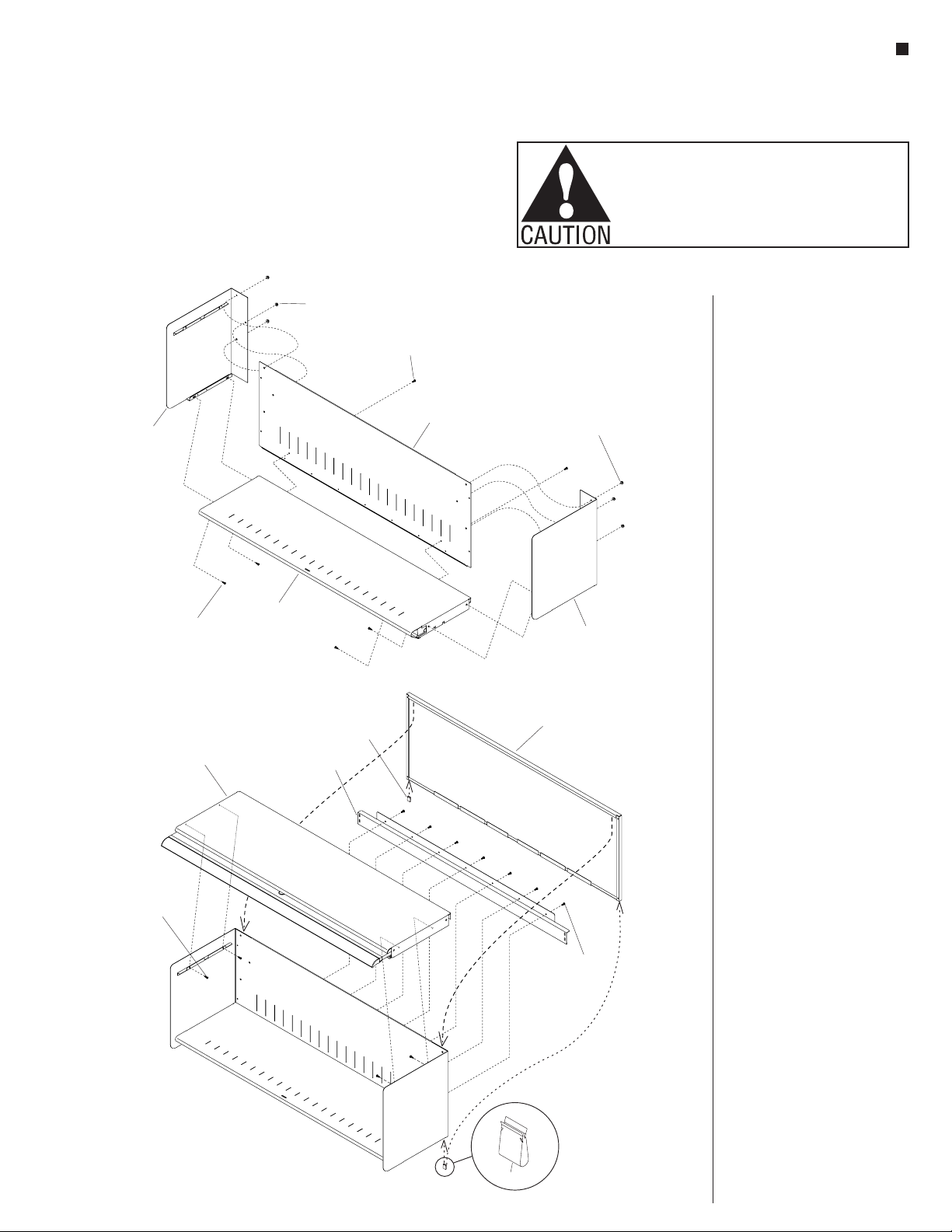
1. Orient the shelf back to the right-and left-hand
cabinet sides as illustrated. Position therear
vertical mounting flanges of both cabinet sides
so the three studs on each end of the shelf back
go through the three holes in each cabinet side.
Place son each of the
three studs at each end and secure cabinet sides
to the shelf back (Figure 1).
3. At the lower rear of the shelf back, secure the
shelf back to the back edge of the bottom shelf
using two #8-32x½” screws (Figure 1).
4. Carefully set the top shelf/cabinet door down
onto the top mounting flanges of the cabinet
sides. Align mounting holes and secure using
two
#10-24 serrated nut
1. Move the bottom shelf into position between
the cabinet shelves, above the lower mounting
flanges and toward to the shelf back. Nest the
bottom shelf down onto the cabinet side lower
mounting flanges and align mounting holes.
Secure the bottom shelf to the cabinet sides
from underneath, at each end using two #8-32
x½” screws (Figure 1).
#8-32x½” screws at each side from
inside the cabinet (Figure 2).
5. Position the stiffener beam to the lower rear of
the cabinet assembly, align mounting holes and
secure using seven #8-32x½” screws (Figure
2).
6. Orient the back plate as illustrated and hang it
onto the back of the cabinet such that the top
vertical flange of the back plate captures the top
inside edge of the shelf back. Use the two barb
clips provided and press them up at the
underside of the cabinet to attach the bottom of
th back plate to the bottom, rear of the shelf
back (Figure 2).
bottom shelf
top shelf
& cabinet door stiffener
beam
back
plate
barb clip
barb clip
shelf back
shelf back
cabinet side
(left-hand)
cabinet
side
cabinet side
(right-hand)
#8-32x½”
screw
#10-24
serrated nut
#10-24
serrated nut
#8-32x½”
screw
#8-32x½”
screw
#8-32x½”
screw
Figure 2
Figure 1
WorkZone Universal Overhead Cabinet
Figure 1
Figure 2
1. Orient the shelf back to the
right-and left-hand cabinet
sides as illustrated. Position the
rear vertical mounting flanges of
both cabinet sides so the three
studs on each end of the shelf
back go through the three holes
in each cabinet side. Place
#10-24 serrated nuts on each of
the three studs at each end and
secure cabinet sides to the shelf
back (Figure 1).
2. Move the bottom shelf into
position between the cabinet
shelves, above the lower
mounting flanges and toward to
the shelf back. Nest the bottom
shelf down onto the cabinet side
lower mounting flanges and
align mounting holes. Secure
the bottom shelf to the cabinet
sides from underneath, at each
end using two #8-32 x ½”
screws (Figure 1).
3. At the lower rear of the shelf
back, secure the shelf back to
the back edge of the bottom
shelf using two #8-32 x ½”
screws (Figure 1).
4. Carefully set the top shelf/
cabinet door down onto the top
mounting flanges of the cabinet
sides. Align mounting holes and
secure using two #8-32 x ½”
screws at each side from inside
the cabinet (Figure 2).
5. Position the stiffener beam to
the lower rear of the cabinet
assembly, align mounting holes
and secure using #8-32 x ½”
screws supplied (Figure 2).
6. Orient the back plate as
illustrated and hang it onto the
back of the cabinet such that the
top vertical flange of the back
plate captures the top inside
edge of the shelf back. Use the
two barb clips provided and
press them up at the underside
of the cabinet to attach the
bottom of th back plate to the
bottom, rear of the shelf back
(Figure 2).

Other BCE Indoor Furnishing manuals


Popular Indoor Furnishing manuals by other brands

Regency
Regency LWMS3015 Assembly instructions

Furniture of America
Furniture of America CM7751C Assembly instructions

Safavieh Furniture
Safavieh Furniture Estella CNS5731 manual

PLACES OF STYLE
PLACES OF STYLE Ovalfuss Assembly instruction

Trasman
Trasman 1138 Bo1 Assembly manual

Costway
Costway JV10856 manual


