BCM MX852-C6 User manual

Embedded Motherboard
MX852-C6
All-in-One Celeron M Mini-ITX Board
With LVDS FP, Audio out,4 COM Ports,
6 USB 2.0 and 10/100 Ethernet
User’s Manual
http://www.bcmcom.com

Declaratio
n
Rights:
No part of this manual, including but not limited to the products and software described in it, may
be reproduced, transmitted, transcribes, stored in a retrieval system, or translated in any form or by
any means without the expressed written permission from the manufacturer.
Products and corporate names appearing in this manual may or may not be registered trademarks or
copyrights of their respective companies and are used only for identification or explanation
purposes without intent to infringe.
zPentium M
®
are registered trademarks of Intel Corporation, .
zMicrosoft and Windows
®
are registered trademarks of Microsoft Corporation.
zPhoenix
®
and Award
®
are registered trademarks of Phoenix Technologies LTD..
Responsibility:
This manual is provided “As-Is” with no warranties of any kind, either expressed or implied,
including, but not limited to the implied warranties or conditions of this product’s fitness for any
particular purpose. In no event shall we be liable for any loss of profits, loss of business, loss of
data, interruption of business, or indirect, special, incidental, or consequential damages of any kind,
even the possibility of such damages arising from any defect or error in this manual or product. We
reserve the right to modify and update the user manual without prior notice.
WARNING:
Replace your system’s CMOS RAM battery only with the identical CR-2032 3V Lithium-Ion coin
cell (or equivalent) battery type to avoid risk of personal injury or physical damage to your
equipment. Always dispose of used batteries according to the manufacturer’s instructions, or as
required by the local ordinance (where applicable).
References:
This manual is created and written by BCM Technical Dept., but not limited, to the information
from the MX852-C6 External Production Specifications, and MX852-C6 Specifications. If any

Compliance & Certificate
C
Co
om
mp
pl
li
ia
an
nc
ce
e
&
&
C
Ce
er
rt
ti
if
fi
ic
ca
at
te
e
ISO 9001 Certificate:
This device was produced in our plant with advanced quality system certified by DNV QA Ltd. in
according to ISO 9001. This Certificate is valid for:
DESIGN & MANUFACTURE OF MOTHERBOARD AND PERSONAL COMPUTERS.
CE Declaration:
CE marking is a visible declaration by the manufacturer or his authorized representatives
that the electrical equipment to which it relates satisfies all the provisions of the 1994
Regulations.
FCC Compliance:
FCC stands for Federal Communications Commission.
This product complies with FCC Rules Part 15 and has been tested, and complied with the EMI
rules by a certified body. In normal operation, there shall be no harmful interference caused by this
device nor shall this device accept any interference received, including interference that may cause
undesired operation of this product.

Easy Installatio
n
E
Ea
as
sy
y
I
In
ns
st
ta
al
ll
la
at
ti
io
on
n
Easy Installation Steps
The following “Easy Installation” steps are for users
accustomed to the assembly of a computer system. For those
individuals requiring more specific information, please refer
to the more detailed descriptions located within the latter
chapters of this manual.
Note: You must keep your power cable unplugged until the
following installation steps are completed.
Getting Started
-Touch a grounded metal surface to release static electricity
stored in your body before unpacking your motherboard. For
details please refer to Precaution.
-Install the 3.3 volt un-
b
uffered DDR SDRAM into the 184
pin DIMM slots.
-Plug in any peripheral card(s) that you want to be included in
the setup.
-Plug in all cables included in the package except for the
power cord.
-Please recheck all steps to ensure no mistakes have been
made and then plug in the power cord and turn on the power
to enter the BIOS setup, Chapter 3.

i
USER’S NOTICE 1
MANUAL REVISION INFORMATION 1
COOLING SOLUTIONS 1
CHAPTER 1 INTRODUCTIONOFMX852-C6 MOTHERBOARD
1-1 FEATURE OF MOTHERBOARD 3
1-2 SPECIFICATION 4
1-3 SYSTEM DIAGRAM 5
1-4 JUMPER & CONNECTOR 6
CHAPTER 2 HARDWARE INSTALLATION
2-1 HARDWARE INSTALLATION STEPS 8
2-2 CHECKING MOTHERBOARD'S JUMPER SETTING 8
2-3 INSTALL CPU 9
2-3-1 GLOSSARY 9
2-3-2 ABOUT INTEL Celeron M 600 CPU 10
2-4 INSTALL MEMORY 11
2-5 EXPANSION CARD 12
2-5-1 PROCEDURE FOR EXPANSION CARD INSTALLATION 12
2-5-2 ASSIGNING IRQ FOR EXPANSION CARD 12
2-5-3 INTERRUPT REQUEST TABLE FOR THIS MOTHERBOARD 13
2-6 CONNECTORS, HEADERS 14
2-6-1 CONNECTORS 14
2-6-2 HEADERS 16
2-7 STARTING UP YOUR COMPUTER 21
CHAPTER 3 INTRODUCING BIOS
3-1 ENTERING SETUP 22
3-2 GETTING HELP 22
3-3 THE MAIN MENU 23
3-4 STANDARD CMOS FEATURES 25
3-5 ADVANCED BIOS FEATURES 27
3-5-1 CPU FEATURE 30
3-6 ADVANCED CHIPSET FEATURES 31
3-6-1 DRAM TIMING SETTINGS 32
3-7 INTEGRATED PERIPHERALS 34
3-7-1 ONBOARD IDE FUNCTION 35
3-7-2 ONBOARD DEVICE FUNCTION 36
3-7-3 ONBOARD SUPER IO FUNCTION 37
3-8 POWER MANAGEMENT SETUP 39
3-9 PNP/PCI CONFIGURATION SETUP 42
3-10 PC HEALTH STATUS 43
3-11 FREQUENCY/ VOLTAGE CONTROL 44
3-12 LOAD FAIL SAFE/OPTIMIZED DEFAULTS 44
3-13 SET SUPERVISOR/USER PASSWORD 45
MX852-C6 Mechanical Drawing 46
TABLE OF CONTENT

1
Manual Revision Information
Reversion Revision History Date
1.0 First Release Jan. 2006
Item Checklist
5
MX852-C6
5
80 wire ATA66/100 IDE cable
5
34 wire Floppy cable
5
Audio line out cable
5
CD for motherboard utilities
5
Standard I/O Shield for MX852-C6
5
MX852-C6 User’s Manual on CD (Digital Format)
5
MX852-C6 Quick Reference Guide
5
Custom CPU Heat Sink

2
Intel Celeron M Processor Family
The MX852-C6 has been design with Intel® 852GM GMCH and Intel® ICH-4 for Embedded
Computing, with build-in optimized integrated graphics solution with a 400 MHz system bus and
integrated 32-bit 3D core at 133 MHz. It features a low-power design, supports the Intel®
Celeron® M processors and up to 1 GB with x16 of DDR 266 memory support.
Intel's platform architecture delivers the performance and high scalability required for today's
cutting-edge embedded computing applications. The Intel 852GM GMCH and ICH-4 are part of
Intel's comprehensive validation process that enables fast deployment of next-generation platforms
to maximize competitive advantage while minimizing development risks
.

3
Chapter 1
Introduction
1-1 Feature of motherboard
The MX852-C6 combines the high performance and exceptional value of Intel
®
852GM
chipset with a full-featured, new generation, industrial board. The Intel
®
852GM chipset support
Celeron
®
M processor of 600MHz up to 2.1GHz, that memory base on the FSB 400 MHz
operation supports DDR SDRAM interface. In the meantime, the 852GM chipset integrated the
LVDS & VGA function. The MX852-C6 system memory size can be up to 1GB DDR memory,
onboard Intel
®
82562ET Ethernet controllers (support 10/100 Base-TX Ethernet), Audio Line-Out
and 4 COM ports, besides the MX852-C6 with four USB2.0 ports on rear panel and two internal
USB2.0 ports header. This board meet today market demand of low power consumption, for POS,
Kiosk and embedded applications.
The 82801DB I/O Controller Hub (ICH4) employs the Intel
®
Accelerated Hub Architecture
to make a direct connection from the graphics and memory, IDE controllers supports (ATA/33 or
ATA/66 or ATA/100), 6 USB ports that are supported USB 1.1/ 2.0 standard performance,
stability and reliability requirements.
The MX852-C6 Mini ITX Board is a valuable and it is suitable for all the industry
applications, which also well support with the Windows
®
98/ 2000/ XP/ NT and Linux operating
system.
MX852-C6 does provide scalability with high reliability & Longevity for Embedded Application.
It is really a wise choice of today computing solution.

4
1-2 Specification
Spec Description
Design ∗Mini ITX form factor 6 layers PCB size: 6.69”(W) x 6.69”(D) (170 x
170 mm)
Chipset ∗Intel 82852GM GMCH Chipset
∗Intel 82801DB ICH4 Chipset
CPU
∗Intel Celeron M 600Mhz processor 0 Cache.
∗System bus Frequency 400 FSB
Video Display
∗Intel 852GM chipset integrated LVDS & graphic controller
∗Intel Extreme II High Performance 2D/3D, resolution up to 1600
x1200 UXGA
∗Support Dual 18-bit LVDS Interface
Memory Socket ∗184-pin DDR SDRAM module socket 1x
∗Support Memory Type 128-Mbit, 256-Mbit, 512M-bit x8/x16
Technology
∗Support 1M, 2M, 4M, 8M, 32M, 64M x N DRAMs
∗Support DDR200/266 SDRAM
∗Expandable to 1GB with x16 Devices
Expansion Slot ∗1x 32-bit PCI slot
∗PCI Rev 2.2 compliant
Integrate IDE ∗Two PCI IDE controllers support PCI Bus Mastering, ATA
PIO/DMA and the ULTRA DMA 33/66/100 functions that deliver
the data transfer rate up to 100 MB/s
* One CF socket support
LAN On Board ∗1x Intel 82562ET 10/100 Ethernet LAN
Audio ∗AC’97 Digital Audio controller integrated
∗AC’97 2.2 Audio CODEC on board
∗Sound Blaster Pro compliant
∗Audio driver and utility included
BIOS ROM ∗4MB Flash ROM
I/O ∗PS/2 keyboard and PS/2 mouse connectors
∗Floppy disk drive connector x1
∗Parallel port x1, Serial port x4 (Three on header)
∗USB 2.0 connector x6, (2 on header)
∗Audio connector CD-In
∗Audio connector Line-Out
BIOS ∗Award (Phoenix PNP BIOS)
∗APM /ACPI compliant
Power ∗ATX standard 20-pin power connector
5
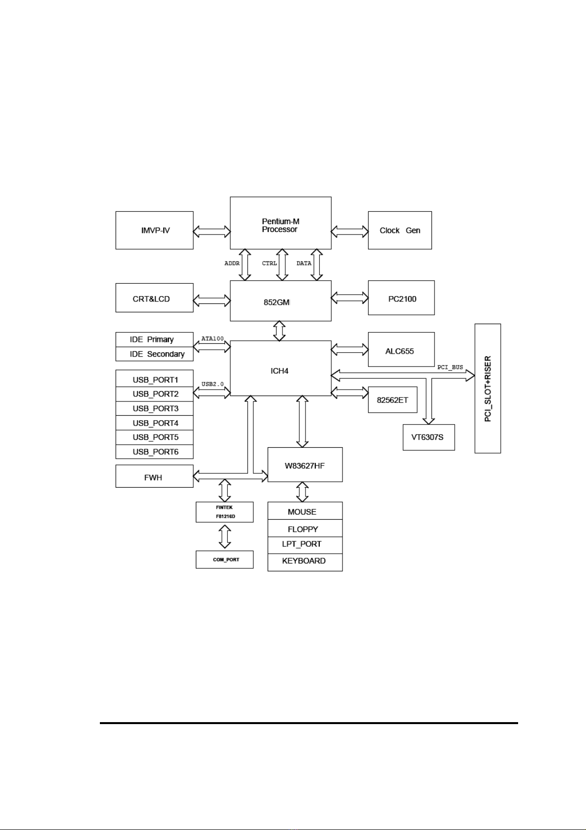
1-3 System Diagram
MX852-C6 Mainboard Diagram
6
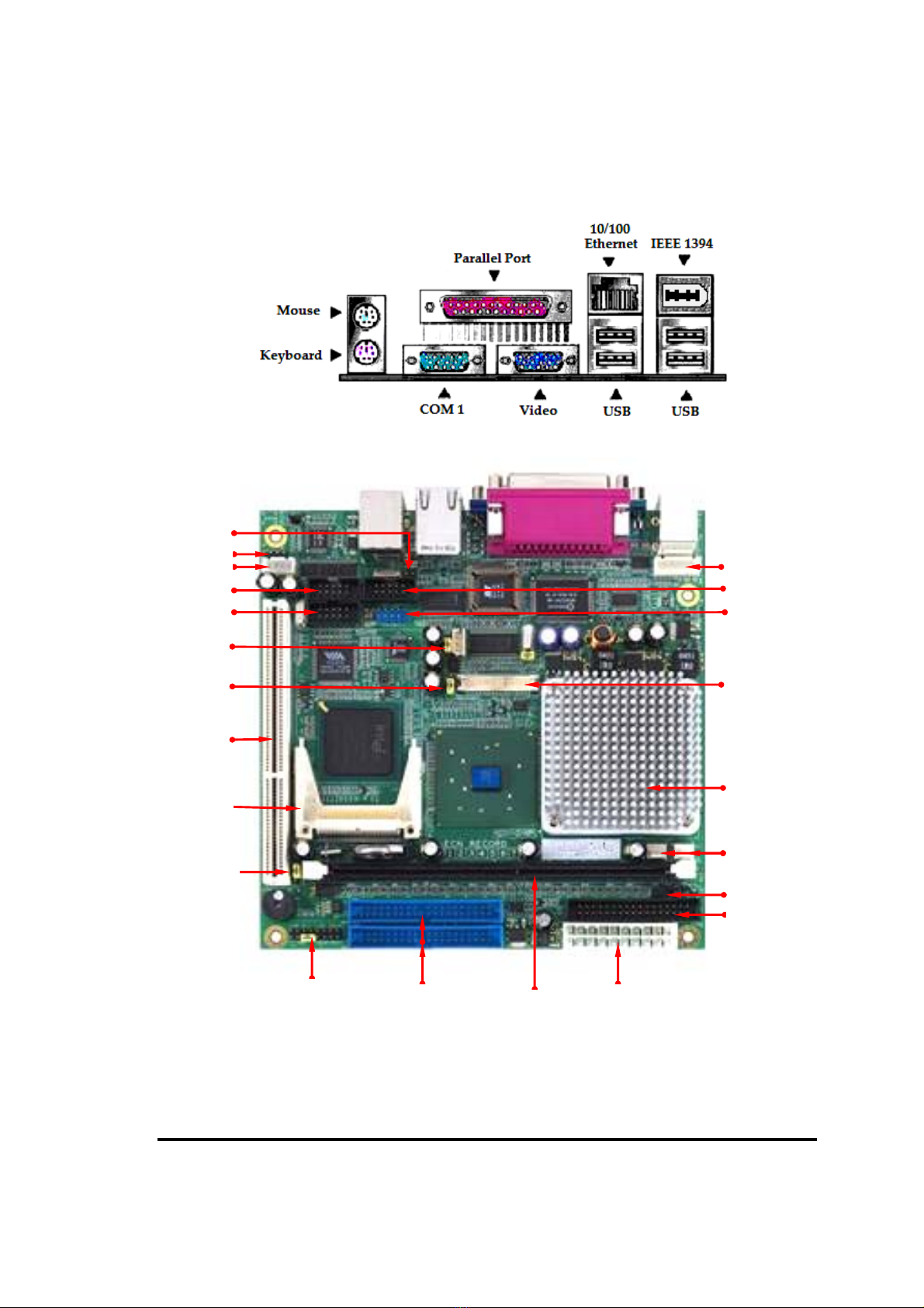
Jumper & Connector
CD-In
Line-Out
Clear CMOS
USB 4/5
DFP LVDS
Primary/ Secondary
IDE
Front Panel ATX Power
COM 2
Ext. KB/
CPU
Floppy
Auto PW
R
-On
System Fan
CPU Fan
DDR DIMM
LAN LED
PCI
COM 3
COM 4
CF Slot
BIOS WP
LED VCC

7
Jumpers
Jumper Name Description Page
JP1 Reserved (FSB Settings) 2-pin Block
JP2 LVDS Voltage Settings Select 3-pin Block
JP3 Clear CMOS Settings Select 3-pin Block
JP4 Auto Power ON 2-pin Block
JP5 BIOS Write Protect 3-pin Block
Connector / Header
Socket/Slot Name Description Page
CN1 CRT VGA Port Front Panel DB-15C Female Connector
CN2 COM1 DB9 Connector
CN3 Parallel Port DB25 Connector
CN4 USB 0, 1/ LAN 5-pin Block (2.54mm pitch)
CN5 PS/2 Keyboard & Mouse 6-pin Mini DIN Connector
CN6 USB 2/3 & 1394 USB & 1394 Connector
CN7 CD-IN 4-pin Connector
CN8 Ext Keyboard & Mouse Connector 5-pin Connector
CN9 Audio Line-Out 4-pin Waver Block
CN10 COM3 Port Header 10-pin Block (2.54mm pitch)
CN11 COM2 Port Header 10-pin Block (2.54mm pitch)
CN12 USB 4/5 Header 9-pin Block (2.54mm pitch)
CN13 COM4 Port Header 10-pin Block (2.54mm pitch)
CN14 SMBUS 3-pin Connector
CN15 DFP LVDS Panel Connector 40-pin Block (HIROSE DF13-40DP)
CN16 32Bit PCI slot
CN17 System Fan Header 3-pin Connector
CN18 CPU Fan Header 3-pin Connector
CN19 Floppy 34-pin Connector
CN20 Secondary IDE 40-pin Connector
CN21 Front Panel 16-pin Block (2.54mm pitch)
CN22 ATX Power 20-pin Block
CN23 Primary IDE 40-pin Connector
CN24 LAN LED Pin Header 4-pin Block
8
Chapter 2
Hardware installation
2-1 Hardware installation Steps
Before using your computer, you had better complete the following steps:
1. Check motherboard jumper setting
2. Install CPU Heatsink
3. Install System Memory (DIMM)
4. Install Expansion cards
5. Connect IDE and Floppy cables, Front Panel /Back Panel cable
6. Connect ATX Power cable
7. Power-On and Load Standard Default
8. Reboot
9. Install Operating System
10. Install Driver and Utility
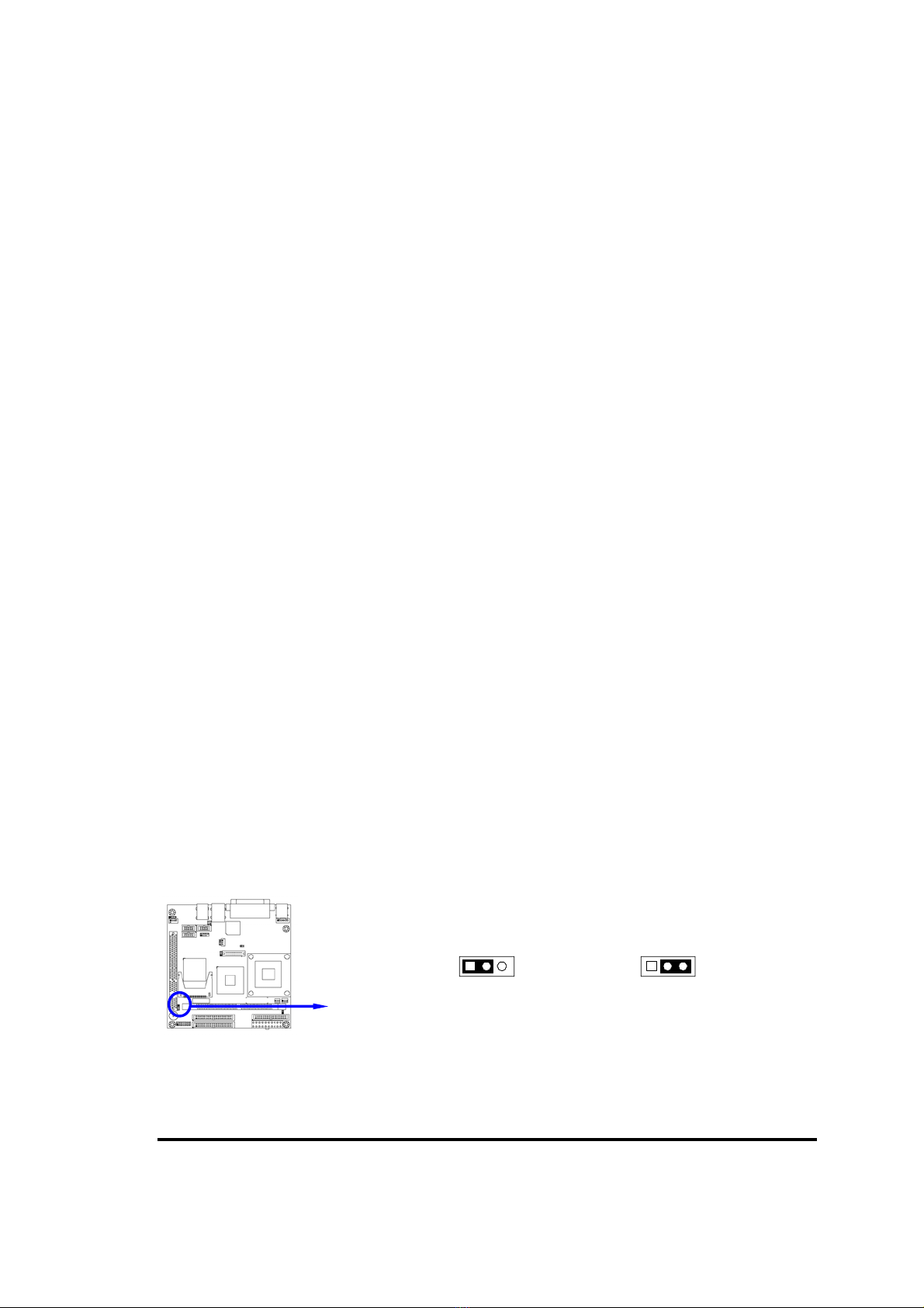
2-2 Checking Motherboard’s Jumper Setting
(1) CMOS RAM clear (3-pin): JP3
A battery must be used to retain the motherboard configuration in CMOS RAM,
short 2-3 pins of JP3 to clear the CMOS data.
To clear the CMOS, follow the procedure below:
1. Turn off the system and unplug the AC power
2. Remove ATX power cable from ATX power connector
3. Locate JP3 and short pins 2-3 for a few seconds
4. Return JP3 on its normal setting by shorting pins 1-2
5. Connect ATX power cable back to ATX power connector
Note: When should clear CMOS
1. Troubleshooting
2. Forget password
3. After over clocking system boot fail
CMOS RAM Clear Setting
JP3
1 3
2-3 closed Clear CMOS
JP3
1 3
1-2 closed Normal (Default)

9
2-3 Install CPU
2-3-1 Glossary
Chipset (or core logic) – A highly integrated circuits which control the interfaces
between the system processor, RAM, I/O devises, and adapter cards.
Processor slot/socket - the slot or socket used to mount the system processor on the
motherboard.
Slot (AGP, PCI, ISA, RAM) - the slots used to mount adapter cards and system RAM.
PCI - Peripheral Component Interconnect - a high speed interface for video cards, sound
cards, network interface cards, and modems; runs at 33MHz.
ISA - Industry Standard Architecture - a relatively low speed interface primarily used for
sound cards and modems; runs at approx. 8MHz.
Serial Port - a serial data transfer interface typically used for mouse and external
modems.
Parallel Port - a parallel data transfer interface typically used for printers.
PS/2 - a low speed interface used for mouse and keyboards.
USB - Universal Serial Bus - a PnP connect interface used for mouse, keyboards,
scanners, printers, hard drive, DVD/ CDROM and digital cameras.
Sound (interface) - the interface between the sound card or integrated sound connectors
and speakers, MIC, game controllers, and MIDI sound devices.
LAN (interface) - Local Area Network - the interface to your local area network.
BIOS (Basic Input/Output System) - the program logic used to boot up a computer and
establish the relationship between the various components.
Driver - software, which defines the characteristics of a device for use by another device
or other software.
Processor - the "Central Processing Unit" (CPU); the principal integrated circuit used for
doing the "computing" in "personal computer"
Front Side Bus Frequency - the working frequency of the motherboard, which is
generated by the clock generator for CPU, DRAM and PCI BUS.
CPU L2 Cache - the flash memory inside the CPU, normally Intel P4 CPU has 512K or
above, while Celeron M 600MHz has 0K.

10
2-3-2 About Intel Celeron M
This motherboard provides with build in Celeron M 600MHz with 32K L1 cache, 0K L2
cache processor.
The combination of Celeron M 600MHz and 852GM chipsets provide a x86-base low
cost, low power, low heat dissipation and high compatibility solution for mobile
embedded application.
The CPU should have a good ventilation to prevent overheating. If this is not the case,
then make sure the CPU has a sufficient cooling to dissipate heat generate from the CPU.
WARNING!
Be sure that there is sufficient air circulation across the processor’s
heatsink and Chassis FAN is working correctly, otherwise it may
cause the processor and motherboard overheat and damage, you may
install an auxiliary cooling FAN, if necessary.

11
2-4 Install Memory
This motherboard provides one 184-pin DIMM (DUAL INLINE MEMORY MODULES)
sites for memory expansion available to maximum memory size of 1.0GB DDR SDRAM.
•Support 128Mb, 256Mb, 512Mb technologies implemented as x8, x16 devices.
•Non-ECC DIMMS.
Valid Memory Configurations
Bank 184-Pin DIMM Total Memory
Bank 0, 1 (DDR0) 200 /266 DDR SDRAM Module X1 64MB∼1.0GB
Total System Memory (Max. 1.0GB) 1 64MB∼1.0GB
NOTE! Make sure the installed memory are DDR266 SDRAM support 133MHz
memory clock, otherwise the system may hang during startup.
Generally, installing DDR SDRAM modules to your motherboard is very easy, refer to
figure 2-4 to see what a 184-Pin DDR200/DDR266 SDRAM module looks like.
DDR1 (BANK0+BANK1)
NOTE! When you install DIMM module fully into the DIMM socket the eject tab
should be locked into the DIMM module very firmly and fit into its indention
on both sides.
WARNING! For the DDR SDRAM CLOCK is set at 133MHz, use only DDR266-compliant
DDR Modules. When this motherboard operate at 133Mhz, most system will
not even boot if non-compliant modules are used because of the strict timing
issues, if your SDR Modules are not DDR266-compliant, set the DDR
SDRAM clock to 100MHz to ensure system stability.

12
2-5 Expansion Cards
WARNING! Turn off your power when adding or removing expansion cards or other system
components. Failure to do so may cause severe damage to both your
motherboard and expansion cards.
2-5-1 Procedure For Expansion Card Installation
1. Read the documentation for your expansion card and make any necessary hardware or
software setting for your expansion card such as jumpers.
2. Remove your computer’s cover and the bracket plate on the slot you intend to use.
3. Align the card’s connectors and press firmly.
4. Secure the card on the slot with the screen you remove above.
5. Replace the computer system’s cover.
6. Set up the BIOS if necessary.
7. Install the necessary software driver for your expansion card.
2-5-2 Assigning IRQs For Expansion Card
Some expansion cards need an IRQ to operate. Generally, an IRQ must exclusively
assign to one use. In a standard design, there are 16 IRQs available but most of them are
already in use.
Standard Interrupt Assignments
IRQ Priority Standard function
0 N/A System Timer
1 N/A Keyboard Controller
2 N/A Programmable Interrupt
3 * 8 Communications Port (COM2)
4 * 9 Communications Port (COM1)
5 * 6 Onboard Display Controller
6 * 11 Floppy Disk Controller
7 * 7 Printer Port (LPT1)
8 N/A System CMOS/Real Time Clock
9 * 10 ACPI Mode when enabled
10 * 3 IRQ Holder for PCI Steering
11 * 2 IRQ Holder for PCI Steering
12 * 4 PS/2 Compatible Mouse Port
13 N/A Numeric Data Processor
14 * 5 Primary IDE Channel
15 * 1 Secondary IDE Channel
* These IRQs are usually available for ISA or PCI devices.

13
2-5-3 Interrupt Request Table For This Motherboard
Interrupt request are shared as shown the table below:
INT A INT B INT C INT D INT E INT F INT G INT H
Slot 1 INTB# INTC# INTD# INTA#
IMPORTANT! If using PCI cards on shared slots, make sure that the drivers
support “Shared IRQ” or that the cards don’t need IRQ assignments.
Conflicts will arise between the two PCI groups that will make the
system unstable or cards inoperable.

14
2-6 Connectors, Headers
2-6-1 Connectors
(1) Power Connector (20-pin block): ATXPWR (CN22)
ATX Power Supply connector is a 20-pins connector comply with Intel ATX
standard. The ATX Power Supply allows to use soft power on with a momentary
switch that connect from the front panel switch to 2-pins Power On jumper pole on
the motherboard. When the power switch on the back of the ATX power supply
turned on, the full power will not come into the system board until the front panel
power switch is momentarily pressed. Press this power switch again will turn off
the power to the system board.
PIN ROW2 ROW1
1 3.3V 3.3V
2 -12V 3.3V
3 GND GND
4 Soft Pwr On 5V
5 GND GND
6 GND 5V
7 GND GND
8 -5V Power OK
9 +5V +5V (for Soft Logic)
10 +5V +12V
Pin 1
(2) PS/2 Mouse & PS/2 Keyboard Connector: PS2 KB/MOUSE (Mini DIN 6)
Connectors for PS/2 keyboard and PS/2 Mouse.
(3) USB Port connector: USB (USB1/ 2/ 3/ 4)
Connectors are 4-pin connector that connect USB devices to the system board.
(4) LAN Port connector: LAN (RJ45)
Connector is standard RJ45 connector for Network connector.
(5) Parallel Port Connector: LPT (25-pin female)
Parallel Port connector is a 25-pin D-Subminiature Receptacle connector. The On-
board Parallel Port can be disabled through the BIOS SETUP. Please refer to
Chapter 3 “INTEGRATED PERIPHERALS SETUP” section for more detail
information.
(6) Audio Connector : ( 3.5mm Mini Jack)
This heater allow you to connect a LINE-OUT
Line-out : Audio output to speaker
(7) VGA Connector: VGA (15-pin D-Sub)
VGA is the 15-pin D-Subminiature female connector for display monitor.
(8) Serial Port COM1: (DB9 Male)
COM1 is the 9-pin D-Subminiature male connector. The On-board serial port can
be disabled through BIOS SETUP. Please refer to Chapter 3 “INTEGRATED
PERIPHERALS SETUP” section for more detail information.

15
(9) Floppy drive Connector (34-pin block): FDD (CN19)
This connector supports the provided floppy drive ribbon cable. After connecting the
single plug end to motherboard, connect the two plugs at other end to the floppy
drives.
10) Primary IDE Connector (40-pin block): IDE1 (CN23)
This connector supports the provided IDE hard disk ribbon
cable. After connecting the single plug end to motherboard,
connect the two plugs at other end to your hard disk(s). If
you install two hard disks, you must configure the second
drive to Slave mode by setting its jumpers accordingly.
Please refer to the documentation of your hard disk for the jumper settings.
Signal Pin Signal
GND 1 2 DRVDEN0#
GND 3 4 NC
GND 5 6 DRVDEN1#
GND 7 8 INDEX#
GND 9 10 MOA#
GND 11 12 DSB#
GND 13 14 DSA#
GND 15 16 MOB#
GND 17 18 DIR#
GND 19 20 STEP#
GND 21 22 WD#
GND 23 24 WE#
GND 25 26 TRAK0#
GND 27 28 WPT#
GND 29 30 RDATA#
GND 31 32 SIDE1#
GND 33 34 DSKCHG#
Signal PIN Signal
GND 1 2 DACT#
DCS3# 3 4 DCS1#
DA2 5 6 DA0
NC 7 8 DA1
NC 9 10 IRQ14
GND 11 12 DACK#
GND 13 14 IORDY
GND 15 16 IOR#
GND 17 18 IOW#
GND 19 20 DREQ
NC 21 22 GND
D15 13 24 D0
D14 15 26 D1
D13 17 28 D2
D12 19 30 D3
D11 31 32 D4
D10 33 34 D5
D9 35 36 D6
D8 37 38 D7
GND 39 40 RESET#
Primary IDE Connector
Pin 1
IDE1
Floppy Drive Connector
Pin 1
FDD
Table of contents
Other BCM Motherboard manuals


