BCM HPM-621UA User manual

Part No: E2047A2S000R
HPM-621UA
Supports single 2nd Gen. Intel® Xeon® Scalable
Processors / Intel® Xeon® Scalable Processors up
to 150W TDP
User’s Manual
1st Ed –03 March 2021

HPM-621UA User’s Manual
FCC Statement
THIS DEVICE COMPLIES WITH PART 15 FCC RULES. OPERATION IS
SUBJECT TO THE FOLLOWING TWO CONDITIONS:
(1) THIS DEVICE MAY NOT CAUSE HARMFUL INTERFERENCE.
(2) THIS DEVICE MUST ACCEPT ANY INTERFERENCE RECEIVED INCLUDING
INTERFERENCE THAT MAY CAUSE UNDESIRED OPERATION.
THIS EQUIPMENT HAS BEEN TESTED AND FOUND TO COMPLY WITH THE LIMITS
FOR A CLASS "A" DIGITAL DEVICE, PURSUANT TO PART 15 OF THE FCC RULES.
THESE LIMITS ARE DESIGNED TO PROVIDE REASONABLE PROTECTION AGAINST
HARMFUL INTERFERENCE WHEN THE EQUIPMENT IS OPERATED IN A
COMMERCIAL ENVIRONMENT. THIS EQUIPMENT GENERATES, USES, AND CAN
RADIATE RADIO FREQUENCY ENERGY AND, IF NOT INSTALLED AND USED IN
ACCORDANCE WITH THE INSTRUCTION MANUAL, MAY CAUSE HARMFUL
INTERFERENCE TO RADIO COMMUNICATIONS.
OPERATION OF THIS EQUIPMENT IN A RESIDENTIAL AREA IS LIKELY TO CAUSE
HARMFUL INTERFERENCE IN WHICH CASE THE USER WILL BE REQUIRED TO
CORRECT THE INTERFERENCE AT HIS OWN EXPENSE.
Notice
This guide is designed for experienced users to setup the system within the shortest time.
For detailed information, please always refer to the electronic user's manual.
Copyright Notice
Copyright 2021 ALL RIGHTS RESERVED.
No part of this document may be reproduced, copied, translated, or transmitted in any form
or by any means, electronic or mechanical, for any purpose, without the prior written
permission of the original manufacturer.
Trademark Acknowledgement
Brand and product names are trademarks or registered trademarks of their respective
owners.
Disclaimer
We reserve the right to make changes, without notice, to any product, including circuits
and/or software described or contained in this manual in order to improve design and/or
performance. We assume no responsibility or liability for the use of the described
product(s), conveys no license or title under any patent, copyright, or masks work rights
to these products, and makes no representations or warranties that
2 HPM-621UA User’s Manual

HPM-621UA User’s Manual
3
User’s Manual
these products are free from patent, copyright, or mask work right infringement, unless
otherwise specified. Applications that are described in this manual are for illustration
purposes only. We make no representation or warranty that such application will be
suitable for the specified use without further testing or modification.
Life Support Policy
OUR PRODUCTS ARE NOT FOR USE AS CRITICAL COMPONENTS IN LIFE
SUPPORT DEVICES OR SYSTEMS WITHOUT THE PRIOR WRITTEN APPROVAL .
As used herein:
1. Life support devices or systems are devices or systems which, (a) are intended for
surgical implant into body, or (b) support or sustain life and whose failure to perform,
when properly used in accordance with instructions for use provided in the labeling, can
be reasonably expected to result in significant injury to the user.
2. A critical component is any component of a life support device or system whose
failure to perform can be reasonably expected to cause the failure of the life
support device or system, or to affect its safety or effectiveness.
A Message to the Customer
Customer Services
Each and every product is built to the most exacting specifications to ensure reliable
performance in the harsh and demanding conditions typical of industrial
environments. Whether your new device is destined for the laboratory or the factory floor,
you can be assured that your product will provide the reliability and ease of operation.
Your satisfaction is our primary concern. Here is a guide to our customer services. To
ensure you get the full benefit of our services, please follow the instructions below
carefully.
Technical Support
We want you to get the maximum performance from your products. So if you run into
technical difficulties, we are here to help. For the most frequently asked questions, you can
easily find answers in your product documentation. These answers are normally a lot more
detailed than the ones we can give over the phone. So please consult the user’s
manual first.

4 HPM-621UA User’s Manual
HPM-621UA User’s Manual
Product Warranty
We warrant to you, the original purchaser, that each of its products will be free from
defects in materials and workmanship for two years from the date of purchase.
This warranty does not apply to any products which have been repaired or altered by
persons other than repair personnel authorized, or which have been subject to misuse,
abuse, accident or improper installation. We assume no liability under the terms of
this warranty as a consequence of such events. Because of our high quality-control
standards and rigorous testing, most of our customers never need to use our repair
service. If any of our products is defective, it will be repaired or replaced at no charge
during the warranty period. For out-of-warranty repairs, you will be billed according to the
cost of replacement materials, service time, and freight. Please consult your dealer for
more details. If you think you have a defective product, follow these steps:
1. Collect all the information about the problem encountered. (For example,
CPU type and speed, products model name, hardware & BIOS revision
number, other hardware and software used, etc.) Note anything abnormal
and list any on-screen messages you get when the problem occurs.
2. Call your dealer and describe the problem. Please have your manual, product,
and any helpful information available.
3. If your product is diagnosed as defective, obtain an RMA (return material
authorization) number from your dealer. This allows us to process your good
return more quickly.
4. Carefully pack the defective product, a complete Repair and Replacement
Order Card and a photocopy proof of purchase date (such as your sales
receipt) in a shippable container. A product returned without proof of the
purchase date is not eligible for warranty service.
5. Write the RMA number visibly on the outside of the package and ship it
prepaid to your dealer.

User’s Manual
HPM-621UA User’s Manual
5
Content
1. Getting Started............................................................................................................8
1.1 Safety Precautions .................................................................................................... 8
1.2 Packing List ............................................................................................................... 8
1.3 Document Amendment History ................................................................................. 9
1.4 Manual Objectives ................................................................................................... 10
1.5 System Specifications ............................................................................................. 11
1.6 Architecture Overview—Block Diagram .................................................................. 15
2. Hardware Configuration...........................................................................................16
2.1 Product Overview .................................................................................................... 17
2.2 Jumper and Connector List ..................................................................................... 18
2.3 Setting Jumpers & Connectors ............................................................................... 21
2.3.1 ME Firmware Recovery (JME_RCVR1) ......................................................................................... 21
2.3.2 Flash Descriptor Security override (JME1) .................................................................................... 21
2.3.3 BMC strap setting (JBMC_DB1) .................................................................................................... 22
2.3.4 Clear CMOS (JCMOS1) ................................................................................................................. 22
2.3.5 CPLD strap setting for BMC Present or not (JBMC_PST1) ........................................................... 23
2.3.6 CPLD JTAG setting (JCPLD_JTAG_EN1) ..................................................................................... 23
2.3.7 CPLD DEBUG header (JCPLD_DEBUG1) .................................................................................... 24
2.3.8 LPC connector (JLPC1) ................................................................................................................. 24
2.3.9 CPLD JTAG header (JCPLD_JTAG1) ........................................................................................... 25
2.3.10 System fan connector 1 (SYS_FAN1) ....................................................................................... 25
2.3.11 System fan connector 2 (SYS_FAN2) ....................................................................................... 26
2.3.12 System fan connector 3 (SYS_FAN3) ....................................................................................... 26
2.3.13 System fan connector 4 (SYS_FAN4) ....................................................................................... 27
2.3.14 System fan connector 5 (SYS_FAN5) ....................................................................................... 27
2.3.15 System fan connector 6 (SYS_FAN6) ....................................................................................... 28
2.3.16 CPU fan connector (CPU1_FAN1) ............................................................................................ 28
2.3.17 HDD fan connector (HDD_FAN1) .............................................................................................. 29
2.3.18 SPI connector (JSPI1) ............................................................................................................... 29
2.3.19 Serial port 1 connector (JCOM1) ............................................................................................... 30
2.3.20 Serial port 2 connector (JCOM2) ............................................................................................... 30
2.3.21 Serial General Purpose I/O connector (JSGPIO2) .................................................................... 31
2.3.22 ATX 12V power connector (ATX12V1) ...................................................................................... 31
2.3.23 ATX power connector (ATXPWR1) ........................................................................................... 32
2.3.24 Power supply PMBus connector (PMBUS1) .............................................................................. 32
2.3.25 USB3.2 Gen1 connector (JUSB1) ............................................................................................. 33
2.3.26 USB2.0 connector (JUSB2) ....................................................................................................... 33

HPM-621UA User’s Manual
6 HPM-621UA User’s Manual
2.3.27 Front Panel connector (JFP1) .................................................................................................... 34
2.3.28 Inlet Thermal Sensors connector (INLET_SER1) ...................................................................... 34
2.3.29 Outlet Thermal Sensors connector (OUTLET_SER1) ............................................................... 35
2.3.30 HDD Backplane thermal Sensors connector (HDD_SER1) ...................................................... 35
2.3.31 VGA connector (JVGA1) ............................................................................................................ 36
2.3.32 For BMC debug message read (JBMC_UART1) ....................................................................... 36
2.3.33 CASE OPEN connector (JCASE_OPEN1) ................................................................................ 37
3.BIOS Setup....................................................................................................................38
3.1 Introduction ............................................................................................................. 39
3.2 Starting Setup ......................................................................................................... 39
3.3 Using Setup ............................................................................................................ 40
3.4 Getting Help ............................................................................................................ 41
3.5 In Case of Problems ................................................................................................ 41
3.6 BIOS setup .............................................................................................................. 42
3.6.1 Main Menu ...................................................................................................................................... 42
3.6.1.1 System Language .................................................................................................................. 43
3.6.1.2 System Date .......................................................................................................................... 43
3.6.1.3 System Time .......................................................................................................................... 43
3.6.2 Advanced Menu ............................................................................................................................. 43
3.6.2.1 Processor Configuration ........................................................................................................ 44
3.6.2.1.1 CPU P State Control .............................................................................................................. 45
3.6.2.1.2 CPU C State Control ............................................................................................................. 45
3.6.2.1.3 Package C State Control ....................................................................................................... 46
3.6.2.2 Memory Configuration ........................................................................................................... 47
3.6.2.2.1 Memory Topology .................................................................................................................. 48
3.6.2.3 IIO Configuration.................................................................................................................... 48
3.6.2.3.1 Socket0 Configuration ........................................................................................................... 49
3.6.2.3.2 Intel® VT for Directed I/O (VT-d) ........................................................................................... 50
3.6.2.4 PCI Express Configuration .................................................................................................... 50
3.6.2.5 sSATA Configuration ............................................................................................................. 51
3.6.2.6 SATA Configuration ............................................................................................................... 52
3.6.2.6.1 SATA Mode options ............................................................................................................... 53
3.6.2.7 Miscellaneous Configuration ................................................................................................. 53
3.6.2.8 Server ME Configuration ....................................................................................................... 54
3.6.2.9 Trusted Computing ................................................................................................................ 55
3.6.2.10 ACPI Settings ........................................................................................................................ 55
3.6.2.11 Serial Port Console Redirection ............................................................................................ 56
3.6.2.11.1 Legacy Console Redirection Settings ................................................................................... 57
3.6.2.12 Super IO Configuration .......................................................................................................... 58
3.6.2.12.1 Serial Port 1 Configuration .................................................................................................... 58

User’s Manual
HPM-621UA User’s Manual
7
3.6.2.12.2 Serial Port 2 Configuration .................................................................................................... 59
3.6.2.13 USB Configuration ................................................................................................................. 60
3.6.2.14 NVMe Configuration .............................................................................................................. 61
3.6.2.15 Option ROM Dispatch Policy ................................................................................................. 61
3.6.2.16 Network Stack Configuration ................................................................................................. 63
3.6.3 Server Mgmt ................................................................................................................................. 63
3.6.3.1 System Event Log.................................................................................................................. 64
3.6.3.2 Bmc self test log .................................................................................................................... 65
3.6.3.3 BMC network configuration ................................................................................................... 66
3.6.3.4 BMC User Settings ................................................................................................................ 67
3.6.4 Security ......................................................................................................................................... 67
3.6.4.1 Secure Boot ........................................................................................................................... 68
3.6.4.1.1 Key Management ..................................................................................................................... 69
3.6.5 Boot .............................................................................................................................................. 70
3.6.6 Save and exit ................................................................................................................................ 72
3.6.6.1 Save Changes and Reset ...................................................................................................... 72
3.6.6.2 Discard Changes and Reset .................................................................................................. 73
3.6.6.3 Restore Default Values .......................................................................................................... 73
3.6.6.4 Save the User Default Values ............................................................................................... 73
3.6.6.5 Restore the User Default Values ........................................................................................... 73
4. Drivers Installation.......................................................................................................74
4.1 Install Chipset Driver ............................................................................................... 75
4.2 Install VGA Driver .................................................................................................... 76
4.3 Install Ethernet Driver .............................................................................................. 77
4.4 Install VROC Driver ................................................................................................. 78
5. Mechanical Drawing ....................................................................................................80

HPM-621UA User’s Manual
8 HPM-621UA User’s Manual
1. Getting Started
1.1 Safety Precautions
Warning!
Always completely disconnect the power cord from your
chassis whenever you work with the hardware. Do not
make connections while the power is on. Sensitive
electronic components can be damaged by sudden power
surges. Only experienced electronics personnel should
open the PC chassis.
Caution!
Always ground yourself to remove any static charge before
touching the CPU card. Modern electronic devices are very
sensitive to static electric charges. As a safety precaution,
use a grounding wrist strap at all times. Place all electronic
components in a static-dissipative surface or static-shielded
bag when they are not in the chassis.
1.2 Packing List
Before you begin installing your single board, please make sure that the
following materials have been shipped:
1 x HPM-621UA motherboard
1 x I/O Shield

User’s Manual
HPM-621UA User’s Manual
9
1.3 Document Amendment History
Revision
Date
By
Comment
1st
March 2021
Initial Release

HPM-621UA User’s Manual
10 HPM-621UA User’s Manual
1.4 Manual Objectives
We have tried to include as much information as possible but we have not duplicated
information that is provided in the standard IBM Technical References, unless it proved to
be necessary to aid in the understanding of this board.
We strongly recommend that you study this manual carefully before attempting to set
up HPM-621UA or change the standard configurations. Whilst all the necessary
information is available in this manual we would recommend that unless you are
confident, you contact your supplier for guidance.
Please be aware that it is possible to create configurations within the CMOS RAM that
make booting impossible. If this should happen, clear the CMOS settings, (see
the description of the Jumper Settings for details).
If you have any suggestions or find any errors regarding this manual and want to inform us
of these, please contact our Customer Service department with the relevant details.
User’s Manual
HPM-621UA User’s Manual
11
1.5 System Specifications
System
CPU
Supports single 2nd Gen. Intel® Xeon® Scalable Processors / Intel® Xeon®
Scalable Processors up to 150W TDP
BIOS
AMI UEFI BIOS
System Chipset
Intel C621 Chipset
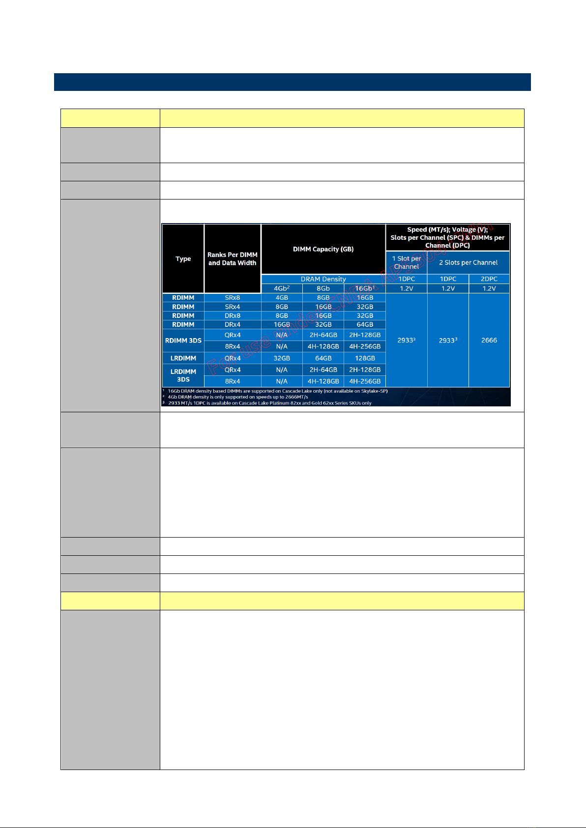
System Memory
6 x DDR4 2933/2666/2400/2133 RDIMM/LRDIMM up to 384GB
Watchdog Timer
System reset event
0~6553 second.
H/W Status
Monitor
Temperature.
Fan.
Voltage.
Case open. (1 x 2.5mm pitch Box Wafer, Pinrex 753-71-02TW07 or equivalent)
Please refer to note 1 for more information.
RAID
Intel C621 software RAID 0,1,5,10
TPM
TPM 2.0 onboard
Other
IPMI 2.0 with AST 2500 BMC controller onboard.
Expansion Slot
PCIe
3 x PCIe x16 slots or 6 x PCIe x8 slots
Slot 1, NA (This is for PCI 3.0 slot)
Slot 2, PCIe 3.0 x8
Slot 3, PCIe 3.0 x16 (x16 will switch to x8 automatically when Slot 2 is used)
Slot 4, PCIe 3.0 x8
Slot 5, PCIe 3.0 x16 (x16 will switch to x8 automatically when Slot 4 is used)
Slot 6, PCIe 3.0 x8
Slot 7, PCIe 3.0 x16 (Slot 7 is the slot closest to CPU, x16 will switch to x8
automatically when Slot 6 is used)
HPM-621UA User’s Manual
12 HPM-621UA User’s Manual
PCI
1 x PCI 3.0 slot
Storage
M.2
1 x M.2 M-Key PCIe 3.0 x4 NVMe SSD
2242/2260/2280 form factor
SATA
9 x SATA III Supports up to 6.0 Gb/s
Edge I/O
LAN
4 x RJ45 (LAN1 share IPMI port)
USB 3.1
4 x USB 3.1
Onboard I/O
COM
2 x RS232 ports (2 x 2.0mm pitch Box Header)
Pin definition: Follow our standard.
USB 2.0
2 x USB 2.0 ports (1 x USB 2.0 2.54mm pitch Box Header)
Pin definition :
VCC
Pin 1
Pin 2
VCC
USB0-
Pin 3
Pin 4
USB1-
USB0+
Pin 5
Pin 6
USB1+
GND
Pin 7
Pin 8
GND
Key
Pin 9
Pin 10
No Connection
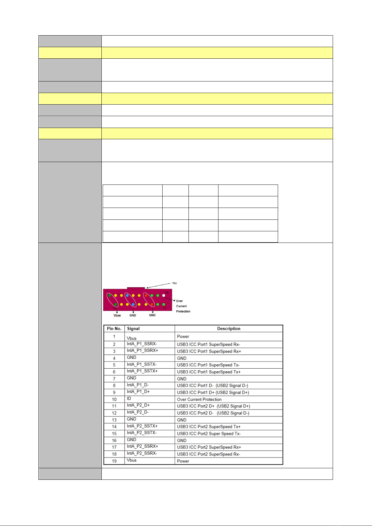
USB 3.1
2 x USB 3.2 Gen1 ports (1 x USB 3.2 Gen1 2.0mm pitch Box Header, Pinrex
52X-8020GB52 or equivalent)
Pin definition :
CPU/System
2 x 4 Pin CPU Fan Header (4 Pin PWM)
User’s Manual
HPM-621UA User’s Manual
13
FAN
5 x 4 Pin Chassis Fan Header (4 Pin PWM)
Buzzer
1 x onboard buzzer
Front Panel
1 x front panel connector (2.54 mm Pitch)
Pin
Function
Pin
Function
1-3
HDD LED
2-4
POWER LED
5-7
RESET BUTTON
6-8
POWER BUTTON
9-11
STATUS LED
10-12
LAN1 ACT LED
13-15
UID LED
14-16
STBY POWER LED
17-19
UID BUTTON
18-20
LAN2-X ACT LED
Notes: LAN2-X ACT LED, “X” means the max number of Ethernet ports.
RTC Battery
1 x Horizontal Socket Type CMOS Battery Holder with CR2450
Clear CMOS
1 x Clear CMOS header (1 x 2.0 mm pitch Header)
LPC
1 x LPC header (2.0 mm pitch header)
Display
Graphic Chipset
1 x VGA port (1 x 2.0mm pitch Box Header)
AST2500 BMC controller
Spec. &
Resolution
1920 x 1200@60Hz 32bpp
Ethernet
LAN Chipset
4 x Intel I210AT
LAN Spec.
1 Gigabit Ethernet Controller
Mechanical &
Environmental
Power
Requirement
1 x Std. 24 pin ATX Connector
2 x 8 Pin SSI 12V Connectors
ACPI
Yes
Power Mode
ATX
Operating Temp.
0 °C to 60 °C
Storage Temp.
-40 °C to 85 °C
Operating
Humidity
40°C 95% non-condensing
Size (L x W)
(Please consult product
engineers for the
production feasibility if
the size is larger than
410x360mm or smaller
than 80x70mm)
ATX form factor
12” x 9.6” (304.8mm x 243.84mm)
Weight
TBD

HPM-621UA User’s Manual
14 HPM-621UA User’s Manual
Vibration Test
Follow our standard test.
Random Vibration Operation
1 Test PSD : 0.00454G²/Hz , 1.5 Grms
2 System condition : operation mode
3 Test frequency : 5~500 Hz
4 Test axis : X,Y and Z axis
5 Test time : 30 minutes per each axis
6 IEC60068-2-64 Test Fh
6 Storage : mSATA
Random vibration test (Non-operation)
1 PSD: 0.00808G²/Hz , 2.0 Grms
2 Non-Operation mode
3 Test Frequency : 5-500Hz
4 Test Axis : X,Y and Z axis
5 30 min. per each axis
6 IEC 60068-2-64 Test:Fh
Package Vibration Test:
1 Test PSD : 0.026G²/Hz , 2.16 Grms
2 Test frequency : 5~500 Hz
3 Test axis : X,Y and Z axis
4 Test time : 30 minutes per each axis
5 IEC 60068-2-64 Test Fh
Drop Test
Follow our standard test.
Reference ISTA 2A, Method : IEC-60068-2-32 Test:Ed
Test Ea : Drop Test
1 Test phase : One corner, three edges, six faces
2 Test high : 96.5cm
3 Package weight : 5Kg
4 Test drawing
OS Information
Windows : Windows 10 IOT Enterprise, Windows server 2016, Windows server
2019
Linux : Ubuntu 16.04 and 18.04
Note: Specifications are subject to change without notice.
User’s Manual
HPM-621UA User’s Manual
15
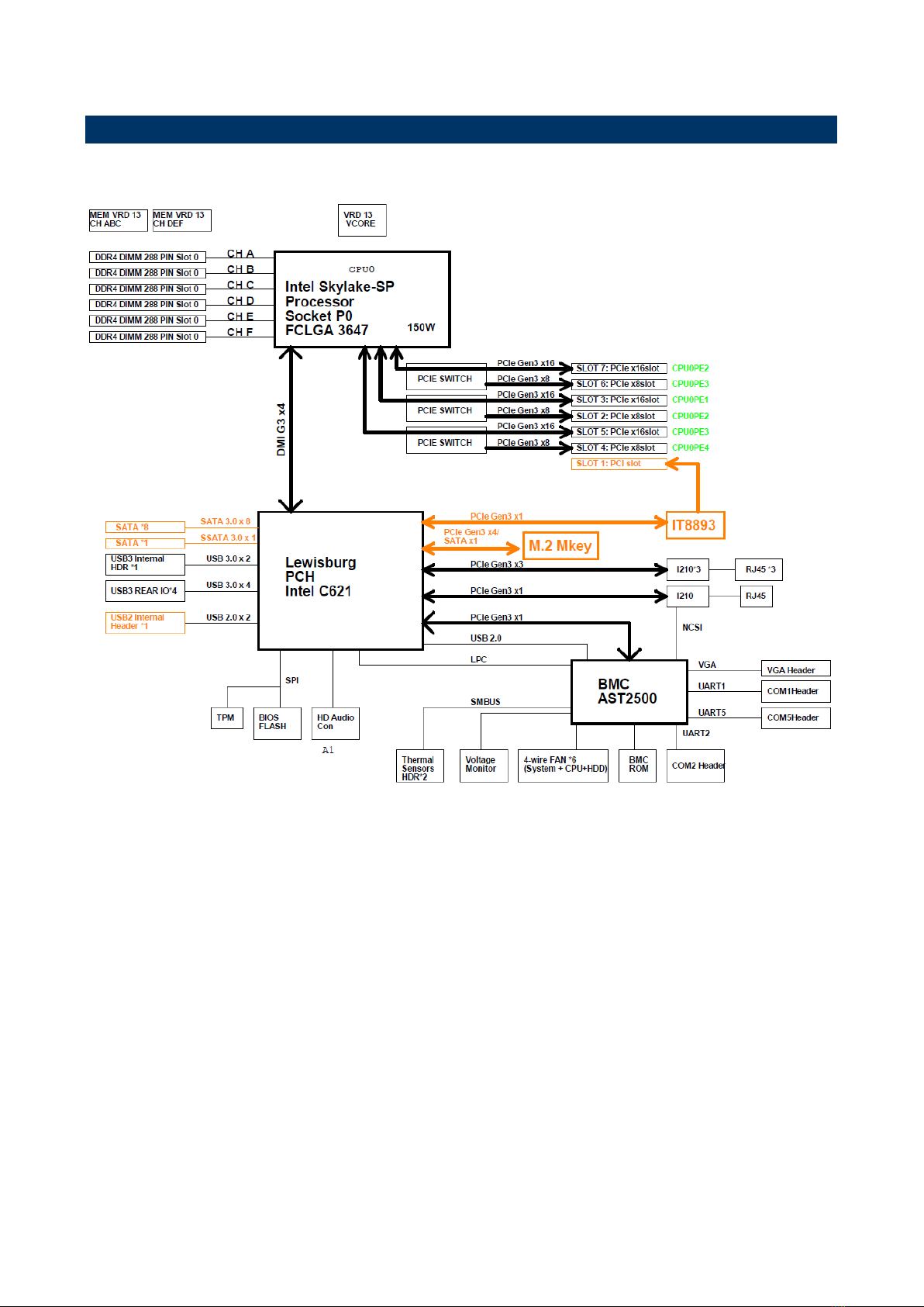
1.6 Architecture Overview—Block Diagram
The following block diagram shows the architecture and main components of HPM-621UA.

HPM-621UA User’s Manual
16 HPM-621UA User’s Manual
2. Hardware
Configuration

User’s Manual
HPM-621UA User’s Manual
17
2.1 Product Overview

HPM-621UA User’s Manual
18 HPM-621UA User’s Manual
2.2 Jumper and Connector List
You can configure your board to match the needs of your application by setting jumpers. A
jumper is the simplest kind of electric switch.
It consists of two metal pins and a small metal clip (often protected by a plastic cover) that
slides over the pins to connect them. To “close” a jumper you connect the pins with the clip.
To “open” a jumper you remove the clip. Sometimes a jumper will have three pins, labeled 1,
2, and 3. In this case, you would connect either two pins.
The jumper settings are schematically depicted in this manual as follows:
A pair of needle-nose pliers may be helpful when working with jumpers.
Connectors on the board are linked to external devices such as hard disk drives, a
keyboard, or floppy drives. In addition, the board has a number of jumpers that allow you to
configure your system to suit your application.
If you have any doubts about the best hardware configuration for your application, contact
your local distributor or sales representative before you make any changes.
The following tables list the function of each of the board’s jumpers and connectors.
Jumpers
Label
Function
Note
JME_RCVR1
ME Firmware Recovery
3 x 1 header, pitch 2.00mm
JME1
Flash Descriptor Security override
3 x 1 header, pitch 2.00mm
JBMC_DB1
BMC strap setting
4 x 2 header, pitch 2.00mm
JCMOS1
Clear CMOS
3 x 1 header, pitch 2.00mm
JBMC_PST1
CPLD strap setting for BMC
Present or not
2 x 1 header, pitch 2.00mm
JCPLD_JTAG_EN1
CPLD JTAG setting
2 x 1 header, pitch 2.00mm
JCPLD_DEBUG1
CPLD DEBUG header
2 x 1 header, pitch 2.00mm
Connectors
Label
Function
Note
SYS_FAN1
System fan connector 1
4 x 1 wafer, pitch 2.54mm

User’s Manual
HPM-621UA User’s Manual
19
SYS_FAN2
System fan connector 2
4 x 1 wafer, pitch 2.54mm
SYS_FAN3
System fan connector 3
4 x 1 wafer, pitch 2.54mm
SYS_FAN4
System fan connector 4
4 x 1 wafer, pitch 2.54mm
SYS_FAN5
System fan connector 5
4 x 1 wafer, pitch 2.54mm
SYS_FAN6
System fan connector 6
4 x 1 wafer, pitch 2.54mm
CPU1_FAN1
CPU fan connector
4 x 1 wafer, pitch 2.54mm
HDD_FAN1
HDD fan connector
4 x 1 wafer, pitch 2.54mm
JCOM1
Serial port 1 connector
5 x 2 wafer, pitch 2.00mm
JCOM2
Serial port 2 connector
5 x 2 wafer, pitch 2.00mm
JSGPIO2
Serial General Purpose I/O
connector 2
3 x 2 wafer, pitch 2.00mm
PCIE2
PCIe 3.0 x8
PCIE3
PCIe 3.0 x16
PCIE4
PCIe 3.0 x8
PCIE5
PCIe 3.0 x16
PCIE6
PCIe 3.0 x8
PCIE7
PCIe 3.0 x16 (Slot 7 is the slot
closest to CPU)
PCI1
PCI 3.0 connector
JFP1
Front Panel connector
10 x 2 wafer, pitch 2.54mm
JUSB12L1
2 x USB3.2 Gen1 connector
1 x RJ-45 Ethernet (LAN1 Share
IPMI Port)
JUSB34L2
2 x USB3.2 Gen1 connector
1 x RJ-45 Ethernet
LAN34
2 x RJ-45 Ethernet
JUSB1
USB3.2 Gen1 connector
10 x 2 wafer, pitch 2.00mm
JUSB2
USB2.0 connector
5 x 2 wafer, pitch 2.54mm
JLPC1
LPC connector
5 x 2 header, pitch 2.00mm
JSPI1
SPI connector
4 x 2 header, pitch 2.00mm
SATA1-4
4 x Serial ATA connector
SSATA1/5/6/7/8
5 x Second Serial ATA connector
DIMM1-6
6 x DDR4 DIMM socket
JBMC_UART1
For BMC debug message read
4 x 1 header, pitch 2.54mm
JCASE_OPEN1
CASE OPEN connector
2 x 1 wafer, pitch 2.50mm
ATX12V1
ATX 12V power connector
4 x 2 wafer, pitch 4.20mm
ATXPWR1
ATX power connector
12 x 2 wafer, pitch 4.20mm

HPM-621UA User’s Manual
20 HPM-621UA User’s Manual
PMBUS1
Power supply PMBus connector
5 x 1 wafer, pitch 2.54mm
INLET_SER1
Inlet Thermal Sensors connector
4 x 1 wafer, pitch 2.00mm
OUTLET_SER1
Outlet Thermal Sensors connector
4 x 1 wafer, pitch 2.00mm
HDD_SER1
HDD Backplane thermal Sensors
connector
5 x 1 wafer, pitch 2.00mm
NGFF1
M.2 M-Key PCIe 3.0 x4 NVMe SSD
CPU1
CPU1 socket
JVGA1
VGA connector
8 x 2 wafer, pitch 2.00mm
JCPLD_JTAG1
CPLD JTAG header
5 x 2 header, pitch 2.54mm
Table of contents
Other BCM Motherboard manuals


