EVGA X299 Micro ATX 2 (121-SX-E296)
- 17 -
Benching systems, or test benches before final assembly, are best served by
using the onboard power because it removes the need to wire a Power/Reset
button or cross posts with a screwdriver, which is a semi-common practice.
This button provides a safer and easier option than jumpering the Power posts.
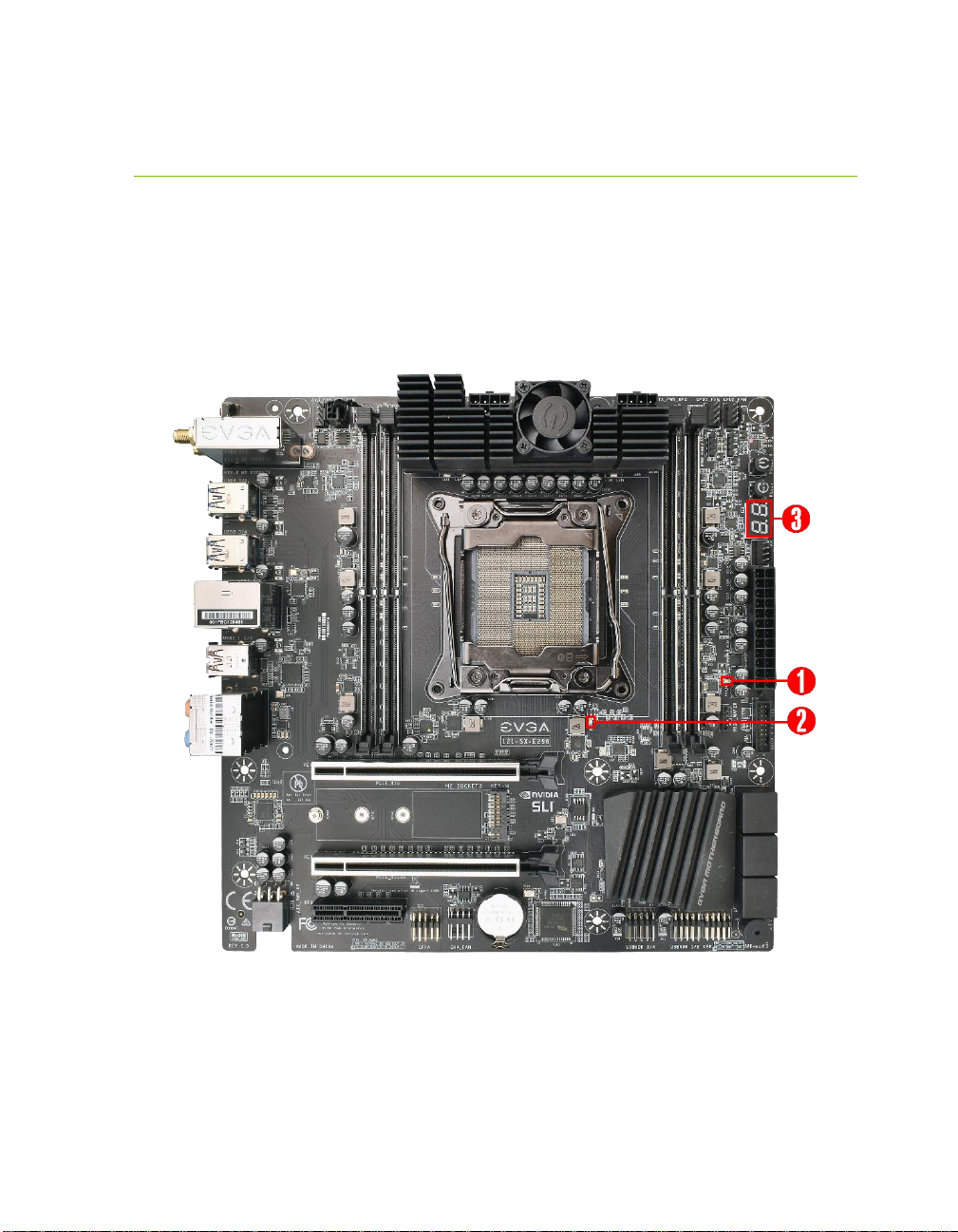
14. Reset Button
This is an onboard system reset button, and may be used in place of, or in
conjunction with, a front panel system reset button wired to the board.
Benching systems, or test benches before final assembly, are best served by
using the onboard power because it removes the need to wire a Power/Reset
button or cross posts with a screwdriver, which is a semi-common practice.
This button provides a safer and easier option than jumpering the Power posts.
15. Debug LED / CPU Temp
This is a two-digit POST code reader, which displays in sets of 7-digit LED.
The display can be configured to show data in regular decimal format, or
hexadecimal, which means the characters available (when working as intended)
are 0-9, A-F and has a cap of 255 characters.
During POST, the LEDs will display the various POST codes as they cycle
through the Power On Self-Test. The POST codes are listed in the
troubleshooting section on Page 130.
After the system boots, it will display the temperature in Celsius. This
temperature is specifically for the CPU socket, which will typically read slightly
higher than a given CPU core. To read this temperature in Fahrenheit, take the
value in Celsius, multiply by 9/5 (or 1.8) and add 32.
16. USB 3.1 Gen 1 Header
The USB 3.1 Gen 1 headers are used to connect additional USB interface plugs
to the motherboard; these headers are most often used to connect the
motherboard to the chassis to enable the USB 3.1 Gen 1 ports on the chassis.
These will function the same as the USB 3.1 Gen 1 ports found on the
motherboard’s hardwired I/O hub, but the Header can be used to attach to
front panel USB, auxiliary ports that mount in the card slots, and also some
devices that directly connect to the header.
USB 3.1 Gen 1 standard available current is 900mA @ 5V for unpowered
devices. If your USB device requires more power than this, it is recommended
to attach a powered USB Hub.
USB 3.1 Gen 2 Type-A (found on the I/O Hub) shares the power limit of USB
3.1 Gen 1 at 900mA @ 5V.