BD Diesel Performance X-monitor 2 User manual

19 November 2008 BD X-Monitor 2 # 1080500 1
BD Engine Brake Inc
A10 – 33733 King Rd, Abbotsford, BC, Canada V2S 7M9
Ship: #88 – 446 Harrison St, Sumas, WA 98295 Mail: PO Box 231, Sumas, WA 98295
Ph: 604.853.6096 Fax: 604.853.8749 Internet: www.bd-power.com
B
BD
D
X
X-
-M
MO
ON
NI
IT
TO
OR
R
2
2
Digital Gauge Monitoring Package
Installation Instructions
P/N# 1080500
*** READ THIS MANUAL & DISCLAIMER COMPLETELY BEFORE INSTALLING THIS PRODUCT ***
Installation Manual P/N#: I1080500

19 November 2008 BD X-Monitor 2 # 1080500 2
BD Engine Brake Inc
A10 – 33733 King Rd, Abbotsford, BC, Canada V2S 7M9
Ship: #88 – 446 Harrison St, Sumas, WA 98295 Mail: PO Box 231, Sumas, WA 98295
Ph: 604.853.6096 Fax: 604.853.8749 Internet: www.bd-power.com
TABLE OF CONTENTS
Accessories......................................................................................................................4
Pillar Mounts.............................................................................................................4
Others.......................................................................................................................4
Tools Needed....................................................................................................................4
Pre-Installation.................................................................................................................4
Installation........................................................................................................................5
Thermocouple Installation ..............................................................................................6
Vehicle Specific Placement.......................................................................................6
Dodge 1998-2006............................................................................................6
Ford 1999-2006...............................................................................................6
GM 2001-2006.................................................................................................7
Generic Installation of the Thermocouple.................................................................7
Pre-Turbo Installation ......................................................................................7
Post-Turbo Installation.....................................................................................8
Wiring Installation............................................................................................................8
Dodge 1998-2002 5.9L.............................................................................................8
Dodge 2003-2006 5.9L...........................................................................................12
Optional Ram Xpower Control #1800505...............................................................15
X-Power Control Wiring Diagram...................................................................16
Optional Ram Fuel Pressure Monitoring Kit #1080150...........................................17
Rail Pressure Sensor (3rd Gen Dodge Only 2003-06) ...................................17
Auxiliary Fuel Pressure..................................................................................17
Wiring Diagram (Fuel Pressure)....................................................................18
Ford 1999-2003 7.3L ..............................................................................................19
Ford 2003-2006 6.0L ..............................................................................................22
Duramax 2001-06...................................................................................................25
Universal Wiring Diagram .............................................................................................28
Display Functions ..........................................................................................................29
Main Menu..............................................................................................................29
Display Menu.................................................................................................30
Alerts Menu....................................................................................................30
Defueling Settings ................................................................................30
Warnings..............................................................................................31
Setup .............................................................................................................31
Backlight...............................................................................................33
Technical Support..........................................................................................................33
19 November 2008 BD X-Monitor 2 # 1080500 3
BD Engine Brake Inc
A10 – 33733 King Rd, Abbotsford, BC, Canada V2S 7M9
Ship: #88 – 446 Harrison St, Sumas, WA 98295 Mail: PO Box 231, Sumas, WA 98295
Ph: 604.853.6096 Fax: 604.853.8749 Internet: www.bd-power.com
KIT CONTENTS:
Please check to make sure that you have all the parts listed in this kit before you start
the disassembly your truck.
1080500 – BD X2 Monitor
1805000 1800508 1800502
X2 Monitor Assembly Monitor Holder Thermocouple w/ Harness
Qty: 1 Qty: 1 Qty: 3
1800503 1800504 1800506
Sensor Fitting Adapters Main Harness
(includes oil sensor) X2 Installation Care Kit
Qty: 3 Qty: 1 Qty: 1
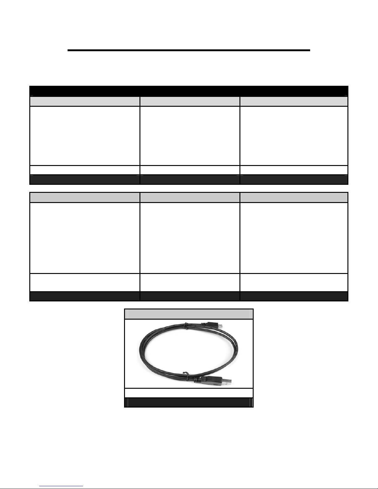
1800507
USB Cable (for internet updates)
Qty: 1
19 November 2008 BD X-Monitor 2 # 1080500 4
BD Engine Brake Inc
A10 – 33733 King Rd, Abbotsford, BC, Canada V2S 7M9
Ship: #88 – 446 Harrison St, Sumas, WA 98295 Mail: PO Box 231, Sumas, WA 98295
Ph: 604.853.6096 Fax: 604.853.8749 Internet: www.bd-power.com
Accessories
Pillar Mounts
P/N# Application
1080570 Powerstroke 1999-2002 7.3L
1080571 Powerstroke 2003-2007 6.0L
1080572 Powerstroke 2007-2008 6.4L
P/N# Application
1080551 Cummins 1998½-2002 24V w/ Speaker
1080553 Cummins 1998½-2002 24V w/o Speaker
1080552 Cummins 2003-2007 24V HPCR
P/N# Application
1080560 Duramax 6.6L 2001-2007 w/o Speaker
1080561 Duramax 6.6L 2001-2007 w/ Speaker
Others
Fuel Pressure Monitoring Kit
P/N# Application
1080150 All
1800505 Ram Xpower Control
Tools Needed
Power Drill, 21/64” Drill Bit, 1/8” NPT Tap, Teflon Tape
Pre-Installation
The BD X2 Monitor is a powerful monitor that has the ability to monitor up to 7 engine
parameters, with up to 4 displaying at a time. However, the X2 still monitors up to all 7
parameters simultaneously with the option to set warnings for up to 6 parameters. De-
fueling options are available based upon 4 of these parameters. While monitoring these
parameters, the X2 also records the highest/lowest value of all parameters being
monitored. In addition to recording the min/max readings you also have the ability to data
log these parameters. The X2 also has the ability to control multiple power modules.
There are many more features to the X2 which will be explained in detail further on in the
manual.

19 November 2008 BD X-Monitor 2 # 1080500 5
BD Engine Brake Inc
A10 – 33733 King Rd, Abbotsford, BC, Canada V2S 7M9
Ship: #88 – 446 Harrison St, Sumas, WA 98295 Mail: PO Box 231, Sumas, WA 98295
Ph: 604.853.6096 Fax: 604.853.8749 Internet: www.bd-power.com
Installation
Choose a location in your vehicle where you want to mount the X2. It is important to do a
test fitting to make sure that is plainly visible while driving, but not an obstruction of your
driving view. We recommend beside the A-Pillar on the driver’s side. The rest of these
instructions assume that you chose this location. If you choose a different location, you
may have to use different techniques to route the cable harness under the dash.
Loosen or remove the A-Pillar. You need the pillar to be loose enough to route the
connectors down the pillar and beside the dash. The ultimate goal is to get the 3
connectors on the end of the cable harness under the dash and below the steering
wheel. Most A-Pillars have plenty of room to route the cable and still install the A-Pillar
back in the factory position without any modifications. It is okay for the pillar to be tight
against the cable as long as it doesn’t have enough pressure to damage the harness.
Once the cable is routed, pull any slack down
under the dash, but leave enough room to stand
the X2 up in the mounted position.
Clip the assembled base onto the X2. Hold the
X2 with the base intact in the position you want
to mount it. Make sure the viewing angle is
correct for the location. If the base needs to be
adjusted, you may do so by using a #2 Phillips
head screwdriver. Simply loosen the 2 screws
holding the base onto the adjustable disk. Do not
remove the screws completely; just loosen them
enough to move the X2’s position. Once you
have your desired angle, tighten the screws.
There are two ways to secure the base to your dash. You may permanently mount it with
the 2 supplied screws or you can use the supplied double sided 3M Tape. This tape is
strong enough to hold your gauge in position and is also removable.
If Using Screws: Holding the X2 in place, carefully mark a spot on the dash on both sides
of the disk where the screw slots are located. Carefully drill a 1/8” hole in these spots for
a pilot hole. You want to make sure to try and drill in the center of the provided slots so
that you leave some room for adjustment. Holding the gauge back into place, carefully
install the screws into the pilot holes. Although the dashes are fairly thick it is important to
not over tighten the screws and strip the plastic material.
If Using Tape: Clean the desired mounting area and the bottom of the mount with the
provided alcohol wipe. Apply the double sided tape to the bottom of the mount. It is best

19 November 2008 BD X-Monitor 2 # 1080500 6
BD Engine Brake Inc
A10 – 33733 King Rd, Abbotsford, BC, Canada V2S 7M9
Ship: #88 – 446 Harrison St, Sumas, WA 98295 Mail: PO Box 231, Sumas, WA 98295
Ph: 604.853.6096 Fax: 604.853.8749 Internet: www.bd-power.com
to only peel one side of the tape protector off at a time. Once you are ready to mount it,
carefully stick it to the dash. Once it is in its desired location, press down firmly onto the
dash. It is best to apply pressure on all parts of the base that has the tape on so it takes a
good hold.
Thermocouple Installation
Vehicle Specific Placement
Please review the recommended positioning for the thermocouple for your specific
vehicle.
Dodge 1998-2006
On the passenger side of the
vehicle locate the exhaust
manifold. On the top side of the
manifold between cylinders #2
and #3 is the ideal location for the
thermocouple.
Ford 1999-2006
On the driver’s side of the
vehicle, locate the exhaust
manifold. You will need to drill
from underneath the vehicle. The
ideal location for the
thermocouple is located just as
the manifold turns up to the turbo
inlet pipe. Make certain that you
drill at an angle that will accept
the length of the thermocouple.

19 November 2008 BD X-Monitor 2 # 1080500 7
BD Engine Brake Inc
A10 – 33733 King Rd, Abbotsford, BC, Canada V2S 7M9
Ship: #88 – 446 Harrison St, Sumas, WA 98295 Mail: PO Box 231, Sumas, WA 98295
Ph: 604.853.6096 Fax: 604.853.8749 Internet: www.bd-power.com
GM 2001-2006
Remove the passenger side
fender well. Once this is removed,
you will see the exhaust manifold.
Towards the rear of the manifold
there is a flange that the manifold
bolts to. Just in front of this flange
is the ideal place to drill for the
thermocouple.
Generic Installation of the Thermocouple
This section provides instructions for the generic installation of the thermocouple.
Pre-Turbo Installation
You must drill a 21/64 hole in your exhaust manifold. There are 2 ways to do this – the
best way is the way that makes you most comfortable. You can remove the manifold to
do this or you can do it on the vehicle while the engine is idling. It is also desirable to drill
a 1/8” pilot hole. Leaving the engine idling will allow any small shavings to safely exit the
exhaust. It is recommended to apply a small amount of grease to the drill bit before
drilling.
Use a 1/8-27 or 1/8NPT tap to make threads in the
hole you just drilled. You will not want to run the tap all
the way into the manifold. This is a tapered tap so the
threads at the top are larger than the ones on the
bottom. You need to tape it far enough to screw the
thermocouple bushing into the manifold.
Screw the thermocouple bushing into the manifold. Be
careful not to over tighten it.
Insert the supplied thermocouple into the bushing and
tighten the locking nut.

19 November 2008 BD X-Monitor 2 # 1080500 8
BD Engine Brake Inc
A10 – 33733 King Rd, Abbotsford, BC, Canada V2S 7M9
Ship: #88 – 446 Harrison St, Sumas, WA 98295 Mail: PO Box 231, Sumas, WA 98295
Ph: 604.853.6096 Fax: 604.853.8749 Internet: www.bd-power.com
Post-Turbo Installation
Drill a 21/64 hole into your turbo down pipe. There is no need for the engine to idle or to
remove the exhaust piece from the truck. The metal shavings will simply exit the exhaust
system when you run the engine.
Use a 1/8-27 or 1/8NPT tap to make threads in the hole you just drilled. You will not want
to run the tap all the way into the manifold. This is a tapered tap, meaning that the
threads at the top are larger than the ones on the bottom. You need to tap it far enough
to screw the thermocouple bushing into the exhaust pipe.
Screw the thermocouple bushing into the pipe. Be careful not to over tighten because it is
easy to strip the threads in the thin exhaust pipe.
Insert the supplied thermocouple into the bushing and tighten the locking nut.
Wiring Installation
Dodge 1998-2002 5.9L
1. Find the lead wire. This is a 2-wire harness with an orange and black wire. The
larger connector needs to be connected to the thermocouple.
2. Route the lead wire across the engine bay to the driver’s side. Tie the lead wire out
of the way of any moving or hot parts to avoid damage to the wires.
3. On the driver’s side firewall there is a rubber plug. Cut a slit in the outer portion of
the plug to route the small connector and wire into the cab.
4. Plug the small 2-wire plug into the corresponding plug on the cable harness.
5. Lay wiring harness #1 out on your engine. The green plug will go inside the cabin
using the same location you routed the lead wire through.
6. Locate the engine’s MAP sensor. This is on the driver’s side of the engine and
behind the fuel filter canister. The year model determines the shape of the
connector.
a. For 1998-2000 trucks, the MAP sensor is round (triangle). There are 2 wires
in the top of the plug and 1 wire in the bottom of the plug. Connect the
supplied T-Tap to the wire that is on the bottom of the plug. This should also
be labeled pin “C” on the connector.

19 November 2008 BD X-Monitor 2 # 1080500 9
BD Engine Brake Inc
A10 – 33733 King Rd, Abbotsford, BC, Canada V2S 7M9
Ship: #88 – 446 Harrison St, Sumas, WA 98295 Mail: PO Box 231, Sumas, WA 98295
Ph: 604.853.6096 Fax: 604.853.8749 Internet: www.bd-power.com
b. For 2001 trucks, the
MAP sensor is an
oval shape. It also
has 3 wires. Connect
the supplied wire tap
to pin “C” on the
plug. To locate pin C,
look at the back of
the plug where the
wires go into the plug
and the retaining clip
is on top, pin “C” is
on the right side.
c. For 2002 trucks, the MAP sensor is also an oval shape, but it also has a
plastic red lock that you must remove to remove the sensor. It also has 3
wires. Connect the supplied T-Tap to the wire that is in the center of the plug.
If you have a power module installed,
you will need to connect to the same
wire on the module’s wiring harness to
receive an accurate reading. Only tap
the wire of the plug that is going into
the sensor. Do not tap the wire on the
factory plug when you are using a
power module. This will result in a
false reading.
7. Connect the blue wire to the T-
Tap.
8. Locate the Engine Coolant Temperature Sensor (ECT) on the front of the engine.
This is a 2-wire connector located on the top of the engine, in front of the valve
cover.
9. Connect the orange wire to the T-Tap.
10. Find the 1/8” male x ¼” female and the ¼” male x 1/8” female brass fittings supplied
in the kit.
11. Screw the ¼” male end of the brass fitting into the ¼” female fitting. Use Teflon tape
to make sure that it will not leak.

19 November 2008 BD X-Monitor 2 # 1080500 10
BD Engine Brake Inc
A10 – 33733 King Rd, Abbotsford, BC, Canada V2S 7M9
Ship: #88 – 446 Harrison St, Sumas, WA 98295 Mail: PO Box 231, Sumas, WA 98295
Ph: 604.853.6096 Fax: 604.853.8749 Internet: www.bd-power.com
12. Screw the supplied 1/8” temperature sensor into the 1/8” female side of the brass
connector.
13. Locate test port #2 on your transmission.
This port is on the passenger side of the
vehicle. The transmission is round on the
front passenger side corner. Moving
towards the rear of the transmission you
will see an inset part of the transmission.
There is a small plug in the test port.
Remove the plug.
14. Using Teflon tape, screw the temperature
probe and fittings into the test port. Do
not over tighten.
15. Route the purple wire from the wiring harness to the temperature sensor.
16. Remove the nut and washers from the sensor and install the purple wire. Replace
the washers and tighten the nut to secure the wire.
17. Go over the wiring harness and secure it to the vehicle, out of harms way using the
supplied wire ties. Keep all wires as far away from moving parts and hot parts of the
engine as possible.
18. Slide the green plug through the rubber grommet where you ran the lead wire. Pull
enough of the wire harness inside the cab so that the switch port connection (white
and black wires) and the black wire with the ring terminal and the red wire with the
fuse tap are inside the cab.
19. Find the bolt located by the firewall and remove it. Place the bolt through the ring
terminal of the black wire and screw it back into its location.
20. Open the fuse box, located on the inside of the truck on the driver’s side of the
dash. You will be required to open the driver’s side door to access the fuse
compartment.
21. Remove fuse #17 and install the fuse tap over the leg of the fuse. Re-install the
fuse.
22. Once everything is secure and installed, you will want to start your engine. The X2
comes pre-set for these 4 parameters. To make sure everything is installed
correctly, use these basic guidelines:

19 November 2008 BD X-Monitor 2 # 1080500 11
BD Engine Brake Inc
A10 – 33733 King Rd, Abbotsford, BC, Canada V2S 7M9
Ship: #88 – 446 Harrison St, Sumas, WA 98295 Mail: PO Box 231, Sumas, WA 98295
Ph: 604.853.6096 Fax: 604.853.8749 Internet: www.bd-power.com
EGT temperatures should be in the 250-350°F (120-175°C) ranges, depending on
engine temperature and outside temperature. Boost pressure should read 0psi at
idle and up to 5psi while revving the engine at the idle position. ECT should be
similar to your factory gauge. If the vehicle is cold, it should read close to ambient
temperature and slowly rise.
Transmission temperature will most likely read ~100°F (35°C). It can take up to 20
miles, depending on the outside temperature, driving style and load to reach
temperatures above 100°F (35°C). Operating temperatures range from 110-180°F
(40-80°C) dependant upon load and driving style.
23. Using the supplied wire ties, tie up the wire and cable harness under the dash.

19 November 2008 BD X-Monitor 2 # 1080500 12
BD Engine Brake Inc
A10 – 33733 King Rd, Abbotsford, BC, Canada V2S 7M9
Ship: #88 – 446 Harrison St, Sumas, WA 98295 Mail: PO Box 231, Sumas, WA 98295
Ph: 604.853.6096 Fax: 604.853.8749 Internet: www.bd-power.com
Dodge 2003-2006 5.9L
1. Find the lead wire. This is a 2-wire harness with an orange and black wire. The
larger connector needs to be connected to the thermocouple.
2. Route the lead wire across the engine bay to the driver’s side. Tie the lead wire out
of the way of any moving or hot parts to avoid damage to the wires.
3. On the driver’s side firewall there is a rubber plug. You can either pop the rubber
plug out or cut a slit in it to route the small connector and wire the cab.
4. Plug the small 2-wire plug into the corresponding plug on the cable harness.
5. Lay wiring harness #1 out on your engine. The green plug will go inside the cabin
using the same location you routed the lead wire through.
6. Locate the engine’s MAP sensor. This is on the driver’s side of the engine, next to
the valve cover. It has 4 wires coming from it.

19 November 2008 BD X-Monitor 2 # 1080500 13
BD Engine Brake Inc
A10 – 33733 King Rd, Abbotsford, BC, Canada V2S 7M9
Ship: #88 – 446 Harrison St, Sumas, WA 98295 Mail: PO Box 231, Sumas, WA 98295
Ph: 604.853.6096 Fax: 604.853.8749 Internet: www.bd-power.com
7. Connect the supplied wire tap to pin “D”. When you look at the back of the plug
where the wires go into the plug and retaining clip is on top, pin “D” is on the right
side. If you have a power module installed, you will need to connect to the same
wire on the module’s wiring harness to receive an accurate reading. Only tap the
wire of the plug that is going into the sensor. Tapping the factory wire when using a
power module will result in a false reading.
8. Connect the blue wire to the wire tap.
9. Locate the Engine Coolant Temperature Sensor (ECT) on the front of the engine.
This is a 2-wire connector located on the top of the engine in front of the valve
cover.
10. Due to having various wire colors used by the factory it is recommended to use a
voltmeter to determine the correct wire. With the key in the on position, check
voltages on both wires. One wire should be ground or read .006 and the other wire
should read .9-3.5V. Connect the wire that has voltage on it. Once the proper wire
is determined, install the supplied T-Tap. On 2003-2004 models you should
connect to pin “2” as labeled on the top of the connector. On 2005-2006 models,
you should connect to pin “B” as labeled on top of the connector.
11. Connect the orange wire to the T-Tap.
12. Find the 1/8” male x ¼” female and the ¼” male x 1/8” female brass fittings supplied
in the kit.
13. Screw the ¼” male end of the brass fitting into the ¼” female fitting. Use Teflon tape
to make sure that it will not leak.
14. Screw the supplied 1/8” temperature
sensor into the 1/8” female side of
your brass connector.
15. Locate test port #2 on your
transmission. This port is on the
passenger side of the vehicle. The
transmission is round on the front
passenger side corner. Moving
towards the rear of the transmission
you will see an inset part of the
transmission. There is a small plug in
the test port. Remove the plug.

19 November 2008 BD X-Monitor 2 # 1080500 14
BD Engine Brake Inc
A10 – 33733 King Rd, Abbotsford, BC, Canada V2S 7M9
Ship: #88 – 446 Harrison St, Sumas, WA 98295 Mail: PO Box 231, Sumas, WA 98295
Ph: 604.853.6096 Fax: 604.853.8749 Internet: www.bd-power.com
16. Using Teflon tape, screw the temperature probe and fittings into the test port. Do
not over tighten.
17. Route the purple wire from the wiring harness to the temperature sensor.
18. Remove the nut and washers from the sensor and install the purple wire. Replace
the washers and tighten the nut to secure the wire.
19. Go over the wiring harness and secure it to the vehicle, out of harms way using the
supplied wire ties. Keep all wires as far away from moving parts and hot parts as
possible.
20. Slide the green plug through the rubber grommet where you ran the lead wire. Pull
enough of the wire harness inside the cab so that the switch port connection (white
and black wires) and the black wire with the ring terminal are inside the cabin.
21. Find the bolt located by the firewall and remove it. Place the bolt through the ring
terminal of the black wire and screw it back into its location.
22. In the engine compartment, locate the red wire with the installed fuse tap.
23. Open the fuse box located under the hood on the driver’s side fender.
24. Remove fuse #28 and install the fuse tap over the leg of the fuse. Re-install the
fuse.
25. Once everything is secure and installed you will want to start your engine. The X2
comes pre-set for these 4 parameters. To make sure everything is installed
correctly, use these basic guidelines:
EGT temperatures should be in the 250-350°F (120-175°C) ranges, depending on
engine temperature and outside temperature. Boost pressure should read 0psi at
idle and up to 5psi while revving the engine at the idle position. ECT should be
similar to your factory gauge. If the vehicle is cold, it should read close to ambient
temperature and slowly rise.
Transmission temperature will most likely read ~100°F (35°C). It can take up to 20
miles, depending on the outside temperature, driving style and load to reach
temperatures above 100°F (35°C). Operating temperatures range from 110-180°F
(40-80°C) dependant upon load and driving style.
26. Using the supplied wire ties, tie up the wire and cable harness under the dash.

19 November 2008 BD X-Monitor 2 # 1080500 15
BD Engine Brake Inc
A10 – 33733 King Rd, Abbotsford, BC, Canada V2S 7M9
Ship: #88 – 446 Harrison St, Sumas, WA 98295 Mail: PO Box 231, Sumas, WA 98295
Ph: 604.853.6096 Fax: 604.853.8749 Internet: www.bd-power.com
Optional Ram Xpower Control #1800505
With the X2 Monitor you now have the ability to control your Dodge Ram Xpower. You
can set EGT limits as well as adjust the horsepower on the fly with a simply up click or
down click.
Follow the below diagram to connect the X2 to the communication controller and then to
the Ram Xpower.

19 November 2008 BD X-Monitor 2 # 1080500 16
BD Engine Brake Inc
A10 – 33733 King Rd, Abbotsford, BC, Canada V2S 7M9
Ship: #88 – 446 Harrison St, Sumas, WA 98295 Mail: PO Box 231, Sumas, WA 98295
Ph: 604.853.6096 Fax: 604.853.8749 Internet: www.bd-power.com
X-Power Control Wiring Diagram
19 November 2008 BD X-Monitor 2 # 1080500 17
BD Engine Brake Inc
A10 – 33733 King Rd, Abbotsford, BC, Canada V2S 7M9
Ship: #88 – 446 Harrison St, Sumas, WA 98295 Mail: PO Box 231, Sumas, WA 98295
Ph: 604.853.6096 Fax: 604.853.8749 Internet: www.bd-power.com
Optional Ram Fuel Pressure Monitoring Kit #1080150
With the X2 Monitor you can also monitor the auxiliary fuel pressure as well as the rail
pressure on your Dodge Common Rail engine (2003-06). If you have a 1999.5 to 2002
Dodge you can utilize the auxiliary fuel pressure sensor only and not the rail pressure
sensor. For the connections you do not reuse, you should zip tie them out of the way.
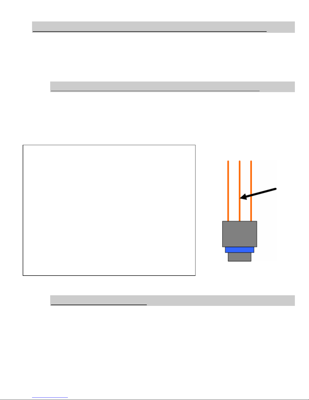
Rail Pressure Sensor (3rd Gen Dodge Only 2003-06)
On the top of the intake to the engine on the driver’s side you will need to locate the rail
pressure sensor. This sensor is a three wire type.
Use the supplied scotk-lok and connect to Pin # 2 or the center wire. With the scotk-lok
connected, then connect the green wire with the male spade connector from the wiring
harness to it.
Auxiliary Fuel Pressure
First you will need to install the supplied banjo bolt and the new sealing washers into the
intake of either the VP44 or CP3. Make sure that you install it into the supply line (larger
line) and not the return line (smaller line). Once the banjo is installed you can install the
fuel pressure sender into the banjo bolt. The thread is 1/8NPT so you will want to snug
the connection up otherwise it will leak. We advise against using Teflon tap as it there is
no filter between this connection and your injection pump. Once this connection is made
you can then attach the ring terminal/yellow wire of the harness.

19 November 2008 BD X-Monitor 2 # 1080500 18
BD Engine Brake Inc
A10 – 33733 King Rd, Abbotsford, BC, Canada V2S 7M9
Ship: #88 – 446 Harrison St, Sumas, WA 98295 Mail: PO Box 231, Sumas, WA 98295
Ph: 604.853.6096 Fax: 604.853.8749 Internet: www.bd-power.com
Wiring Diagram (Fuel Pressure)

19 November 2008 BD X-Monitor 2 # 1080500 19
BD Engine Brake Inc
A10 – 33733 King Rd, Abbotsford, BC, Canada V2S 7M9
Ship: #88 – 446 Harrison St, Sumas, WA 98295 Mail: PO Box 231, Sumas, WA 98295
Ph: 604.853.6096 Fax: 604.853.8749 Internet: www.bd-power.com
Ford 1999-2003 7.3L
1. Find the lead wire. This is a 2 wire harness with an orange and black wire. The
larger connector needs to be connected to the thermocouple.
2. Route the lead wire from the thermocouple to the driver’s side firewall. There is a
plastic plug that is diamond shaped on the firewall. Pop the plug out from the inside.
You can either leave the entire plug out or drill a hole large enough to fit the lead
wire plug and the plug from harness #1 into the cab. Tie the lead wire out of the
way of any moving or hot parts to avoid damage to the wires.
3. Plug the small 2-wire plug into the corresponding plug on the cable harness.
4. Lay wiring harness #1 out on your engine. The green plug will go inside the cab
using the same location you routed the lead wire through.
5. Locate the engine’s MAP sensor. This is on the passenger side of the engine,
beside the hot side of the intercooler tube. It has 3 wires coming from it.
6. Connect the supplied wire tap to the wire in the middle of the connector. If you have
a power module installed you will need to connect to the same wire on the module’s

19 November 2008 BD X-Monitor 2 # 1080500 20
BD Engine Brake Inc
A10 – 33733 King Rd, Abbotsford, BC, Canada V2S 7M9
Ship: #88 – 446 Harrison St, Sumas, WA 98295 Mail: PO Box 231, Sumas, WA 98295
Ph: 604.853.6096 Fax: 604.853.8749 Internet: www.bd-power.com
wiring harness to receive an accurate reading. Only tap the wire of the plug that is
going to the sensor. Tapping the factory wire when using a power module will result
in a false reading.
7. Connect the blue wire to the wire tap.
8. Locate the Engine Oil Temperature Sensor (EOT) towards the front of the engine.
This is a 2-wire connector located on the top of the engine just behind the High
Pressure Oil reservoir. The sensor will be mounted horizontal to the truck. Note: On
the 7.3L engines we monitor the oil
temperature instead of coolant
temperature. This will cause the
temperatures to be slightly higher than
water and you should adjust your
warnings and warm-up module
accordingly.
9. Connect the supplied wire tap to pin
#2. If you are holding the connector
with the clip release facing up and
looking at the back side where the wires enter the connector, then the correct wire
should be on the left side.
10. Connect the orange wire to the wire tap.
11. Locate the high pressure test port on your transmission. This port is on the driver’s
side of the vehicle. There is a
small plug in the test port.
Remove the plug.
12. Using Teflon tape, screw the
temperature probe and fittings into
the test port. Do not over tighten.
13. Route the purple wire from the
wiring harness to the temperature
sensor.
14. Remove the nut and washers from the sensor and install the purple wire. Replace
the washers and tighten the nut to secure the wire.
15. Go over the wiring harness and secure it to the vehicle out of harms way using the
supplied wire ties. Keep all wires far away from any moving or hot parts.
Table of contents
Other BD Diesel Performance Measuring Instrument manuals


