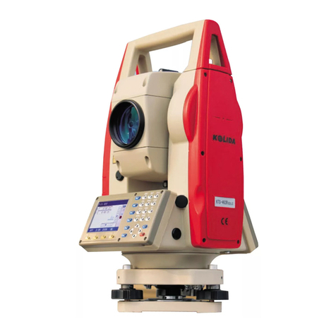
Kolida KTS-470 R Series User manual

1
Contents
FOREWORD ..............................................................................................................................................6
PRECAUTIONS.........................................................................................................................................7
BATTERY NOTIFICATION.....................................................................................................................8
SAFETY GUIDE.........................................................................................................................................9
1. NOMENCLATURE AND FUNCTIONS............................................................................................10
1.1 NOMENCLATURE....................................................................................................................... 10
1.2 KEYPAD ....................................................................................................................................... 12
2. SYNCHRONIZATION WITH PC......................................................................................................13
2.1 MICROSOFTACTIVESYNC INSTALLATION.......................................................................... 13
2.2 CONNECTING TOTALSTATION WITH PC .............................................................................. 13
3. KNOWINGABOUT KTS470(R) ........................................................................................................15
3.1 OPERATING SYSTEM................................................................................................................. 15
3.2 SETTING YOUR TOTALSTATION ............................................................................................ 15
3.2.1 Backlight................................................................................................................................. 15
3.2.2 Touch-screen Adjustment........................................................................................................ 16
3.3APPROACHES TO INPUT NUMERALAND CHARACTER..................................................... 18
4.STAR KEY (★) MODE .....................................................................................................................21
5. PREPARATION FOR MEASUREMENT .........................................................................................24
5.1 UNPACKING AND STORE OF INSTRUMENT ......................................................................... 24
5.2 INSTRUMENT SETUP................................................................................................................. 24
5.3 BATTERY INFORMATION ......................................................................................................... 26
5.4 REFLECTOR PRISM.................................................................................................................... 27
5.5 MOUNTINGAND DISMOUNTING INSTRUMENT FROM TRIBRACH ................................ 28
5.6 EYEPIECEADJUSTMENTAND COLLIMATING OBJECT ..................................................... 29
5.7 VERTICALAND HORIZONTALANGLE TILT CORRECTION................................................ 29
6. BASIC SURVEY...................................................................................................................................30
6.1ANGLE MEASUREMENT........................................................................................................... 31
6.1.1 Horizontal Angle (Right Angle) and Vertical Angle Measurement ......................................... 31

2
6.1.2 Switch Horizontal Angle Right/Left........................................................................................ 32
6.1.3 Horizontal Angle Reading Setting .......................................................................................... 33
6.1.4 Vertical Angle Percentage (%) Mode ..................................................................................... 35
6.1.5 Repeat Angle Measurement.................................................................................................... 36
6.2 DISTANCE MEASUREMENT..................................................................................................... 38
6.2.1 Setting Atmosphere Correction............................................................................................... 39
6.2.2 Atmospheric Refraction and Earth Curvature Correction...................................................... 42
6.2.3 Setting Target Type ................................................................................................................. 43
6.2.4Setting the Prism Constant...................................................................................................... 44
6.2.5Distance Measurement (Continue Measurement) ................................................................... 44
6.2.6 Distance Measurement (Single/N-Time Measurement) .......................................................... 46
6.2.7 Fine/Tracking Measurement Mode......................................................................................... 47
6.3 COORDINATE MEASUREMENT............................................................................................... 47
6.3.1 Setting Coordinate Values of Occupied Point......................................................................... 47
6.3.2 Setting the Backsight Point..................................................................................................... 49
6.3.3 Setting the Instrument Height/ Prism Height.......................................................................... 50
6.3.4 Operation of Coordinate Measurement.................................................................................. 51
7. APPLICATION PROGRAMS.............................................................................................................53
7.1 LAYOUT ....................................................................................................................................... 53
7.2 REMOTE ELEVATION MEASUREMENT (REM)...................................................................... 54
7.2.1 Inputting Prism Height (h) ..................................................................................................... 54
7.2.2 without Inputtingt Prism Height............................................................................................. 56
7.3 MISSING LINE MEASUREMENT (MLM)................................................................................. 57
7.4 LINE MEASUREMENT (LINE)................................................................................................... 60
7.5 TRAVERSE MEASUREMENT (RESTORE NEZ)....................................................................... 63
7.6 OFFSET MEASUREMENT (OFFSET)........................................................................................ 66
7.6.1 Angle Offset ............................................................................................................................ 66
7.6.2 Distance Offset ....................................................................................................................... 68
7.6.3 Column Offset......................................................................................................................... 70
7.6.4 Plane Offset............................................................................................................................ 71
7.7 PARAMETERS SETTING............................................................................................................ 73
8. START STANDARD SURVEYING PROGRAM..............................................................................75
9. PROJECT..............................................................................................................................................78
9.1 CREATE NEW PROJECT............................................................................................................. 78
9.2 OPEN PROJECT ........................................................................................................................... 80
9.3 DELETE PROJECT....................................................................................................................... 81

3
9.4 PROJECT OPTION....................................................................................................................... 82
9.5 GRID FACTOR ............................................................................................................................. 83
10. DATA EXPORT/IMPORT.................................................................................................................85
10.1 DATAEXPORT........................................................................................................................... 85
10.2 DATAIMPORT............................................................................................................................ 87
11. RECORD MEASUREMENT DATA.................................................................................................89
11.1 SETTING OCCUPIED POINTAND BACKSIGHT POINT....................................................... 89
11.2 BACKSIGHT OBSERVATION (BS OBS) ................................................................................ 100
11.3 FORESIGHT OBSERVATION (FS OBS).................................................................................. 101
11.4 SIDESHOT OBSERVATION (SS OBS) .................................................................................... 103
11.4.1 Offset................................................................................................................................... 105
11.4.2 Plane Offset ........................................................................................................................ 108
11.4.3 Pt. Line Mode (For Measurement from Point to Line) ........................................................110
11.4.4 Control Input........................................................................................................................113
11.5 CROSS SECTION SURVEY..................................................................................................... 113
12. EDIT DATA.......................................................................................................................................116
12.1 EDITING RAW DATA .............................................................................................................. 116
12.2 COORD. DATA......................................................................................................................... 119
12.2.1 Edit Coord. Data .................................................................................................................119
12.2.2 Add coord. Data ................................................................................................................. 121
12.2.3 Delete Coord. Data............................................................................................................. 122
12.3 FIXED POINT DATA................................................................................................................ 123
12.4 CODE DATA ............................................................................................................................. 123
12.4.1 Create New Layer............................................................................................................... 124
12.4.2 Edit Layer/Code ................................................................................................................. 126
12.4.3Delete Code......................................................................................................................... 127
12.5 FILL-CUT DATA ...................................................................................................................... 128
13. PROGRAM MENU..........................................................................................................................129
13.1 SET OUT................................................................................................................................... 129
13.1.1 Occupied Point& Backsight Point...................................................................................... 129
13.1.2 Point Set Out ...................................................................................................................... 131
13.1.3 String Setout ....................................................................................................................... 135
13.1.4 Reference line..................................................................................................................... 135
13.2 ROAD DESIGNAND LAYOUT............................................................................................... 142
13.2.1 Define Horizontal Alignment.............................................................................................. 142

4
13.2.2 Edit Alignment.................................................................................................................... 148
13.2.3 Define Vertical Alignment................................................................................................... 150
13.2.4 Edit Vertical Alignment....................................................................................................... 151
13.2.5 Alignment Setout................................................................................................................. 153
13.2.6 Slope Setout........................................................................................................................ 156
13.2.7 Cross Section Setout........................................................................................................... 158
13.3 COGO........................................................................................................................................ 161
13.3.1 Intersection......................................................................................................................... 161
13.3.2 4-Intersection...................................................................................................................... 162
13.3.3 Inverse................................................................................................................................ 164
13.3.4 Area .................................................................................................................................... 165
13.3.5 Missing Line Measurement................................................................................................. 168
13.3.6 Radiate ............................................................................................................................... 135
13.4 TRAVERSE ADJUSTMENT..................................................................................................... 171
13.5 BATTER BOARDS ................................................................................................................... 178
13.5.1 Method 1: Batter board using two sides............................................................................. 178
13.5.2 Method 2: Batterboards using one side.............................................................................. 181
13.6 TAPE DIMENSIONS ................................................................................................................ 183
14. SYSTEM SETTINGS.......................................................................................................................187
15. CHECK AND ADJUSTMENT........................................................................................................190
15.1 PLATE VIAL............................................................................................................................. 190
15.2 CIRCULAR VIAL..................................................................................................................... 190
15.3 INCLINATION OF RETICLE................................................................................................... 191
15.4 PERPENDICULARITY BETWEEN LINE OF SIGHTAND HORIZONTALAXIS (2C) ....... 192
15.5 VERTICALINDEX DIFFERENCE COMPENSATION........................................................... 194
15.6ADJUSTMENT OF VERTICALINDEX DIFFERENCE (IANGLE)AND SETTING
VERTICALINDEX 0........................................................................................................................ 194
15.7 TRANSVERSE AXIS ERROR COMPENSATIONADJUSTMENT........................................ 196
15.8 OPTICALPLUMMET .............................................................................................................. 198
15.9 INSTRUMENT CONSTANT(K)......................................................................................... 199
15.10 PARALLELBETWEEN LINE OF SIGHTAND EMITTING PHOTOELECTRICAXIS...... 201
15.11 TRIBRACH LEVELING SCREW .......................................................................................... 201
15.12 RELATED PARTS FOR REFLECTOR................................................................................... 201
16. TECHNICALSPECIFICATION....................................................................................................203
17. ACCESSORIES ................................................................................................................................205

5
【APPENDIX-A】.................................................................................................................................206
1EXPORT DATAFROM TOTALSTATION.................................................................................... 206
1.1 Raw Data Format.................................................................................................................... 206
1.2 Coordinate Data Format......................................................................................................... 206
2IMPORT DATATO TOTALSTATION .......................................................................................... 207
2.1 Coordinate Data/Fixed Point Data Format ............................................................................ 207
2.2 Cross Section Data Format..................................................................................................... 207
2.3 Point P Coding Format ........................................................................................................... 208
2.4 Horizontal Line........................................................................................................................ 208
【APPENDIX-B】CALCULATE ROAD ALIGNMENT.................................................................210
1ROADALIGNMENT ELEMENTS............................................................................................... 210
2CALCULATION ROADALIGNMENT ELEMENTS................................................................... 211

6
FOREWORD
Thank you for purchasing Electronic Total Station KTS-470 R Series.
KTS-470R is our second generation of Win-Total station, which realizes the
automation and informationization. KTS-470R has smaller size, larger screen and
control panel, it is a computer-like total station.
The WIN-CE interface of 470R is very similar with a Windows-based PC, You can
connect them easily and realize real-time data exchanging and processing on both
ends.
This manual is applicable to: KTS-470(R) Series Total Station.
Please read the manual completely before operating the instrument.

7
PRECAUTIONS
1. Do not collimate the objective lens direct to sunlight without a filter.
2. Do not store the instrument in high and low temperature to avoid the sudden
or great change of temperature.
3. When the instrument is not in use, place it in the case and avoid shock, dust
and humidity.
4. If the temperature varies greatly between work site and the instrument
depository, do not set to work as soon as arrived; leave the instrument in the
case for a while till it adapted environment temperature.
5. When storing the instrument long time without use, disconnect the battery
from the device. The battery should be charged once a month.
6. Please give special attention to the packing Shock absorption is very
important in long distance transportation.
7. For less vibration and better accuracy, the instrument should be set up on a
wooden tripod rather than aluminum tripod.
8. Clean exposed optical parts with degreased cotton or lens tissue only!
9. If the instrument gets wet in the rain, do not try to power it on at once,
Clean the surface with a soft cloth and then keep the instrument in a well
ventilated place.
10. Before set up the job, check initial settings of the instrument as well as the
parameters.
11. Unless the user is a maintenance specialist, do not attempt to disassemble the
instrument by oneself.
12. when the laser is switched on, do not look into the objective Len with naked
eye.

8
BATTERY NOTIFICATION
1.Battery should be recharged only with the charger SC-20 which comes with the
total station.
2 .Battery Recharging Cautions:
The charger has built-in circuitry for protection from overcharging. However, do not
leave the charger plugged into the power outlet after recharging is completed.
Be sure to recharge the battery at a temperature of 0°~±45°C, recharging may be
abnormal beyond the specified temperature range .
Prohibit the use of any charger or battery that has been damaged.
3.Battery Storage Cautions:
Rechargeable battery can be repeatedly recharged 300 to 500 times. Long time totally
discharge of a battery may shorten its life. The battery should be recharged at least one
time a month, which will help increase its full charge capacity. Do not keep the battery
at high heat and damp places. Do not short-circuit the battery.
Dispose of batteries properly. Do not throw them into fire or expose to high
temperature.

9
SAFETY GUIDE
For laser EDM (visible laser)
Warning:
The total station is equipped with an EDM of a laser grade---3R/Ⅲa. It is verified by
the following labels.
Over the vertical tangent screw sticks an indication label “CLASS III LASER
PRODUCT”. A similar label is pasted on the opposite side.
This product is classified as Class 3R laser product, which accords to the following
standards.
IEC60825-1:2001 “SAFETY OF LASER PRODUCTS”.
Class 3R/Ⅲa laser product: It is harmful to observe laser beam continuously. User
should avoid sighting the laser at the eyes. It can reach 5 times the emitting limit of
Class2/II with a wavelength of 400mm-700mm.
Warning:
Continuously looking straight at the laser beam is harmful.
Prevention:
Do not stare at the laser beam, or point the laser beam to others‟ eyes. Reflected laser
beam is a valid measurement to the instrument.
Warning:
When the laser beam emits on prism, mirror, metal surface, window, etc., it is
dangerous to look straight at the reflex.
Prevention:
Do not stare at the object which reflects the laser beam. When the laser is switched on
(under EDM mode), do not look at it on the optical path or near the prism. It is only
allowed to observe the prism with the telescope of total station.
Warning:
Improper operation on laser instrument of Class 3R will bring dangers.
CAUTION
LASER RADIATION-DO NOT
STARE INTO BEAM
620-690nm
CLASS ⅢLASER PRODUCT

10
1. NOMENCLATURE AND FUNCTIONS
1.1 NOMENCLATURE

11

12
1.2 KEYPAD
Functions of the Keys
Key
Nomenclature
Function
Power Key
To switch power ON/OFF.
0~9
Numeric Key
To input desired numbers.
A~/
Alpha Key
To input alphabets.
Inputting Panel
Key
To display inputting panel.
B.S
Backspace
To delete one character leftward when inputting numbers or
alphabets.
Cursor Key
To move the cursor up/down/left/right.
α
Alpha Shifting
Key
To shift to alphabet inputting mode.
★
Star Key
To launch several common functions
ESC
ESC Key
Quit to previous screen or previous mode.
ENT
Enter Key
To finish and accept the data input.

13
2. SYNCHRONIZATION WITH PC
2.1 The Installation of MicrosoftActivesync
There is a CD-ROM attached with the instrument. Put it into your CD-Rom driver, and
install Microsoft ActiveSync, then you can establish activeSync connection between
470R and Computer.
Before Installing Microsoft ActiveSync
Before installing, read the following words carefully:
●During the installation processing, reboot your computer is required. Therefore,
please save your jobs and quit all the applications before installation.
●To install Microsoft ActiveSync, you are supposed to have an USB cable
(available in the product package) connect the PDA with the personal computer.
Installing Microsoft ActiveSync
● Put the CD-ROM into your disk drive.
Microsoft ActiveSync Installation Guide will be run automatically.
● Click “Next” to install Microsoft ActiveSync.
2.2 CONNECTING TOTALSTATION WITH PC
● Connect the 470R and computer with the USB cable.
● Power the total station on. The software will detect the Total station and setup
the communication. When connection established successfully, the following message
will display.

14
Using “Browse” Function
After the synchronization, you can click “Browse” button to view the files stored in the
total station. Copy, paste and deletion are synchronized on both ends. See the picture
below.

15
3. KNOWINGABOUT YOUR KTS-470(R)
Press POWER to turn on the instrument. See the initial interface as below.
3.1 OPERATING SYSTEM
470R is based on Windows CE operating system; WINCE is quite similar to Windows
system. The functions and interfaces are easy to use for the surveyor.
Note: we also provide in KTS-470R two powerful Mapping softwares: WinMG and
WinEG. They can help you finish most of the office work soon after field measuring.
3.2 SETTINGYOUR TOTAL STATION
You can adjust the default settings of 470R according to the following steps.
3.2.1 Backlight adjustment
The system will automatically shut the backlight when battery is running low.
You can also adjust the brightness of backlight as following steps.

16
OPERATIONAL STEPS
KEY
DISPLAY
①Click “Control panel”
On the desktop.
Control panel
②Use stylus to roll the scroll
bar to find “Backlight”
icon.
Backlight
③The brightness of LCD screen
backlight depends on the
position of the cursor.
You can turn on/off the
keyboard backlight by change
the lower option.
[OK]
3.2.2 Touch-screenAdjustment
If your device is not responding accurately to screen taps, Adjust the touch screen by
the following steps.

17
OPERATION STEPS
KEY
DISPLAY
①In “Control panel” find
“adjust” icon.
control panel
+
adjust
②Click “adjust”‟
adjust
+
Calibration
③Click “Calibration”, and
then “Recalibrate”.
Calibration
+
Recalibrate
④According to the prompt,
use the stylus to click the
cross center. Repeat as the
cross moves around the
screen. Totally adjust 5
points as guided.

18
⑤Press [ENT] to save new
setting,
Press [Esc] to return to control
panel.
[ENT]
+
[Esc]
3.3APPROACHES TO INPUT NUMBER AND CHARACTER
For Total Station KTS-470R, two kinds of inputting approaches are available. One is
using the keyboard, like the keyboard of a mobile phone, with 3 characters on one key.
Press it once to display the first characters. Press it twice to display the second one.
And press it three times to display the third character. The other way is using soft
keyboard. Press icon [ ] to enter inputting interface. As an example, here we create a
folder named “Job-1”.
[Example 1:Inputting by soft keyboard]
OPERATION STEPS
KEY
DISPLAY
①Click the “Standard
Survey” with stylus to
open the program.
②Click “project” and
choose “New project” on
the pull-down menu.

19
③Press to open the soft
keyboard
④One can switch between
capital letter and
lower-case though “shift”
on the soft keyboard.
Input “J”.
[shift]
+
[J]
⑤The system automatically
returns to small letter inputting
mode. Use the stylus to click
characters key [o] and [b] to
input “o” and “b”.
[o]
[b]
⑥Click [-] to input “-”
Click number [1] to input “1”.
[-]
[1]

20
⑦After inputting, press the
“Shift” to close the soft
keyboard.
Press [ENT] to create the
current working project.
Press [ ] key to close soft keyboard.
[Example 2:Input by physical keyboard]
OPERATIONAL STEPS
KEY
DISPLAY
①
Click “project” and
choose “New project” on
the pull-down menu.
②Switch to character input
mode by press [α]. then
press [4] one time to input
a capital letter “J‟.
[α]
[4]
③Press [5] twice to input
letter “o”, [7] twice to
input “b”.
[5]
[5]
[7]
[7]
Table of contents
Other Kolida Measuring Instrument manuals

Kolida
Kolida K1 Pro User manual

Kolida
Kolida DL-200 User manual

Kolida
Kolida KTS-442UT Series User manual

Kolida
Kolida KTS440 R Series User manual

Kolida
Kolida KTS440 Series User manual

Kolida
Kolida K3 IMU User manual

Kolida
Kolida K20s User manual

Kolida
Kolida CTS-632R10M User manual

Kolida
Kolida KL-03 User manual

Kolida
Kolida Total Station KTS-462R10L User manual