BE Power Equipment 120 GALLON HORIZONTAL User manual

User Manual
120 GALLON HORIZONTAL
AIR COMPRESSOR
BEPOWEREQUIPMENT
.COM

2

3
table of contents
Introduction
5 Using the Operator’s Manual
Product Identification
6 Record Identification Numbers
Safety
7 Safety Precautions and Warnings
Description
9 Compressor
9 Cooling
9 Controls
Receiving Compressor
10 Receiving and Uncrating your Compressor
Installation
11 Location
11 Mounting
11 Induction System
12 Noise
12 Piping Fitup
13 Pressure Vessels
13 Electrical
14 Pressure Switch
14 Manual Relief and Shutoff Valves
14 Guards
15 Drives
16 Installation Diagram
Start Up Procedure
17 Start Up Preparation & Procedures
Stopping Procedure
18 Stopping for Maintenance or Service
Compressor Diagram
19 3 Phase
20 1 Phase

4
table of contents
Adjustments and Alignment
21 Adjusting Belt Tension
21 Pulley Alignment
Maintenance
22 Daily
22 Weekly
22 Monthly
23 Every 3 Months
23 Storage of Compressor
Breakdown List
24 Compressor Breakdown
Troubleshooting
25 Troubleshooting Chart

5
Adjustments and Alignment
21 Adjusting Belt Tension
21 Pulley Alignment
Maintenance
22 Daily
22 Weekly
22 Monthly
23 Every 3 Months
23 Storage of Compressor
Breakdown List
24 Compressor Breakdown
Troubleshooting
25 Troubleshooting Chart
Using the Operator’s manual
The operating manual is an important part of your Compressor and
should be read thoroughly before initial use, and referred to often to make
sure adequate safety and service concerns are being addressed.
Reading the owner’s manual thoroughly will help avoid any personal injury
or damage to your pump. By knowing how best to operate this machine
you will be better positioned to show others who may also operate the
unit.
You can refer back to the manual at any time to help troubleshoot any
specific operating functions, so store it with the machine at all times.
Attention: Read through the complete
manual prior to the initial use of your
Compressor
introduction

6
product identification
Record Identification Numbers
Compressor
If you need to contact an Authorized Dealer or Customer Service line
(1-866-850-6662) for information on servicing, always provide the
product model and identification numbers.
You will need to locate the model and serial number for the pump and
record the information in the places provided below.
Date of Purchase:
Dealer Name:
Dealer Phone:
Product Identification Numbers
Model Number:
Serial Number:

7
safety
Safety Precautions and Warnings
Listed are some, but not all safety precautions that must be observed
with compressors and compressed air systems. Failure to follow any
of these warnings may result in severe personal injury, death, property
damage and/or compressor damage.
Air from this compressor will cause severe injury or death if used for
breathing or food processing.
Air used for these processes must meet OSHA 29 CFR 1910 or FDA 21
178.3570 regulations.
This compressor is designed for use in the compression of normal
atmospheric air only. No other gases, vapors or fumes should be exposed
to the compressor intake, nor processed through the compressor.
Disconnect all power supplies to the compressor plus any remote
controllers prior to servicing the unit.
Relieve all pressure internal to the compressor prior to servicing.
Do not depend on check valves to hold system pressure.
A properly sized safety valve must be installed in the discharge piping
ahead (upstream) of any shutoff valve (block valve), heat exchanger,
orifice or any potential blockage point. Failure to install a safety relief
valve could result in rupturing or explosion of some compressor or safety
component.
Do not change the pressure setting of the safety relief valve, restrict the
function of the safety relief valve, or replace the safety valve with a plug.
Over pressurization of some system or compressor component can
occur, resulting in severe personal injury, death and property damage.
Never use plastic pipe, rubber hose, or soldered joints in any part of
the compressed air system. Failure to ensure system compatibility with
compressor piping is dangerously unsound.
Never use a flammable or toxic solvent for cleaning the air filter or any
parts.
Do not attempt to service any part while the compressor is operating.
Do not operate the compressor at pressures in excess of its rating.
Do not remove any guards while the compressor is operating.
Observe gauges daily to ensure compressor is operating properly.
Follow all maintenance procedures and check all safety devices on
schedule.
Compressed air is dangerous, do not play with it.
Use the correct lubricant at all times.
8
safety
WARNING
Never apply air pressure to compressor crank case, always make sure
crank case vent is clear and free from obstructions. Adding pressure to
the crank case can cause serious bodily injury or death.
WARNING
Never operate a compressor in a moving vehicle or towable object
in motion. Doing so can damage the compressor, compressor drive
components, or auxiliary parts on the compressor package. Operating
the compressor in a moving vehicle or towable object can cause
serious bodily injury or death.
WARNING
Check function of safety valves, weekly to insure proper function,
replace immediately if faulty or damaged.
WARNING
BE certifies that the electric motor, electrical enclosure and electrical
conduit are rated for NEMA7/hazardous locations. (Only for applicable
packages with NEMA7 added components)
Air compressors have multiple moving parts and potential points of
contact that could create an ignition source. The compressor pumps
are manufactured with ferrous metals and in some cases multiple
moving parts can come in contact with one another causing an ignition
source. BE does not guarantee this will not occur. Lack of maintenance
or care can result in conditions that could also cause ignition sources.
BE only guarantees that the electric motor, electrical enclosure and
electrical conduit are rated for NEMA7 hazardous location. BE accept
no other responsibility for the rating of the package.
WARNING
CALIFORNIA PROPOSITION 65 WARNING:
This product contains lead and other chemicals known to the State
of California to cause cancer, birth defects and/or reproductive harm.
Wash your hands after handling this product.

9
Descriptions
COMPRESSOR
A reciprocating compressor is a piston type pump which develops pres-
sure from the action of a piston moving through a cylinder. The cylinder,
or cylinders, may be vertical, horizontal or angular.
When air is drawn in from the atmosphere and compressed to its final
pressure in a single stroke, the compressor is referred to as a “single
stage” pump. Single stage units normally are used in the 90 to 125 PSI
range and are available as single or multi-cylinder (twin cylinder) com-
pressors.
When the air drawn from the atmosphere is compressed first to an inter-
mediate pressure, and then further compressed to a higher pressure, it is
done in a “two stage” pump. These cylinders are unequal in size and the
first stage always takes place in the larger, low pressure cylinder. From
there it passes through the inner cooler to the smaller, high pressure
cylinder. The cycle is completed as the air then moves through the after
cooler and discharge line into the tank. Two stage compressors are gen-
erally used for pressure ranges from 100 to 175 PSI and deliver more air
per horsepower at these pressures. This increase in efficiency is partially
due to the heat dissipated as the air passes through the inner cooler.
COOLING
Our compressors are cooled by fan blades, incorporated into the driven
sheave (pulley), blowing air across the intercooler, after cooler, and
cylinder head.
CONTROLS
Stop/Start Receiver or plant air system pressure is controlled within limits
by a pressure switch automatically stopping and starting the compressor
as the air pressure reaches a maximum preset pressure (cut out) and
then drops to a minimum presser pressure (cut in).
description
10
Receiving and uncrating your compressor
Before uncrating the compressor the following steps should be taken.
1. Immediately upon receipt of the equipment, it should be inspected
for damage that may have occurred during shipment. If any damage
is found, demand an inspection immediately by an inspector from the
carrier. Ask him how to file a claim for damages.
2. Insure that adequate lifting equipment is available for moving the
machinery.
3. Read the compressor nameplate to be sure the compressor is the
model and size ordered.
4. Read the motor nameplate to be sure the motor is compatible with
your electrical conditions. (Volts-Phase-Hertz).
NOTICE
Standard motors are open drip proof with a maximum ambient
temperature rating of 104 degrees F. They are not suitable for salt
laden, corrosive, dirty, wet, or explosive environments.
CAUTION
Improper lifting can result in component or system damage or personal
injury. Follow good shop practices and safety procedures
CAUTION
Under no circumstances should a compressor be placed in an area that
may be exposed to a toxic, volatile or corrosive atmosphere nor should
toxic, volatile or corrosive agents be stored near the compressor.
IMPORTANT: If voltage supplied to the compressor is below 208 volts
the unit need a 200 Volt drive motor. Motors rated at 208-230-460
Volt should not be used below 208 volts.
receiving compressor

11
NOTICE
For compressor tank to have full manufacturer warranty. The tank must
be installed properly on manufacturer supplied vibration pads per
compressor manual. Failure to do so can void compressor tank
warranty and cause tank cracks or failures.
On Electric compressors all electrical connections must be wired and
installed per NEC (National Electric Code) (See the back of the manual
for NEC code) and all local applicable codes for full electric component
warranty. Failure to do so can void compressor electrical warranty.
Installation
LOCATION
Locate the compressor in an indoor area that is clean, dry, well lighted,
and well ventilated, with sufficient space for safe and proper inspection
and maintenance. Ambient temperatures should not exceed 104 degrees.
For fall below 30 degrees unless an electric motor rated for a higher
temperature is used. Inspection and maintenance checks are required
daily, therefore, ample space is required around the compressor.
The compressor must not be installed closer than fifteen inches from a
wall or from another compressor to allow ample circulation or air across
the compressor cylinders and head, and through the coolers if they are
part of the system. Additional safety can be achieved by locating the
pulley guard next to the wall.
MOUNTING
The use of the factory supplied rubber vibration isolation pads, or other
factory supplied vibration isolation mounting equipment is required for
tank warranty from the original tank manufacturer. The compressor should
never be left on original shipping material for installation. If a shim is
required to level the unit, place it between the pad and floor. If you bolt
the unit to the floor, use the bolts as guide pins and do not tighten the
bolts. The rubber pads are used to absorb machine vibration and cannot
work effectively if bolted tightly.
INDUCTION SYSTEM
Do not locate the compressor where it could ingest or ignite toxic,
explosive or corrosive vapors, ambient air temperatures exceeding 110
degrees F, water or extremely dirty air. Ingestion of any of the above noted
atmospheres by the compressor could jeopardize the performance of the
equipment and all personnel exposed to the total compressed air system.
Destructive pulsations can be induced by reciprocating compressors that
will damage walls and break windows. Pulsation can be minimized by
adding a pulsation dampener on the inlet side of the compressor.
installation
12
NOISE
Noise is a potential health hazard that must be considered. There are
local and federal laws specifying maximum acceptable noise levels
that must not be exceeded. Most of the noise from a reciprocating
compressor originates from the air inlet point. Excessive noise can be
greatly reduced by installing an intake noise silencer.
PIPING FITUP
Care must be taken to avoid assembling the piping in a strain with
the compressor. It should line up without having to spring or twist into
position. Adequate expansion loops or bends should be installed to
prevent undue stresses at the compressor resulting from the changes
between hot and cold conditions. Pipe support should be mounted
independently of the compressor and anchored as necessary to limit
vibration and prevent expansion strains.
installation
DANGER
Safety valves are to protect system integrity in accordance with ASME
Codes and ANSI B19.3 safety standards. Failure to use safety valves
of the proper capacity and pressure will cause severe personal injury or
death.
CAUTION
ASME coded pressure vessels must not be modified, welded, repaired,
reworded or subjected to operation conditions outside the nameplate
ratings. Such actions will negate code status, affect insurance status
and may cause severe personal injury, death, and property damage.
NOTICE
Standard motors are open drip proof with a maximum ambient
temperature rating of 104 degrees F. They are not suitable for salt
laden, corrosive, dirty, wet, or explosive environments.
SAFETY VALVES Safety valves are pressure relief valves and should
be sized and purchased with a pressure setting to protect the weakest
link in the system. Never change the pressure setting, only the safety
valve manufacturer is qualified to make a change. Safety valves are to
be place ahead of any potential blockage point which included but is
not limited to, shutoff valves, heat exchangers, pulsation dampeners,
and discharge silencers.
13
PRESSURE VESSELS
Air receiver tanks and other pressure containing vessels such as, but
not limited to, pulsation bottles, heat exchangers, moisture separators
and traps, shall be in accordance with ASME Boiler and Pressure Vessel
Code Section VIII and ANSI B19.3 Safety Standards.
ELECTRICAL
Before installation, the electrical supply should be checked for adequate
wire size and transformer capacity. During installation a suitable fused or
circuit breaker disconnect switch should be provided. Where a 3 phase
motor is used to drive a compressor, any unreasonable voltage unbalance
between the legs must be eliminated and any low voltage corrected to
prevent excessive current draw. Compressors must be equipped with a
properly wired magnetic motor starter or a pressure switch rated to carry
the full motor current load. The coil which engages and disengages the
contact points in the motor starter is controlled by the pressure switch.
Never attempt to bypass the pressure switch or adjust it past the factory
set pressure range. Improper installation of the electrical system can
cause the motor to overheat or a short circuit to occur.
installation
CAUTION
The installation, wiring, and all electrical controls must be in
accordance with ANSI C1 National Electric Code, ANSE C2 National
Electric Safety Code, state and local codes. All electrical work should
be performed by a qualified electrician. Failure to abide by the national,
state and local codes may result in physical and/or property damage.
CAUTION
Electric power always exists inside the pressure switch when there is
electric power at the compressor package. Either a qualified electrician
should make the pressure adjustments or the electric power supply
should be disconnected and locked out before making any adjustment.
NEVER exceed the designed pressure for the system or overload the
motor beyond its service factor.
FAILURE TO HEED THESE WARNINGS MAY RESULT IN SERIOUS
INJURY OR DEATH, PROPERTY DAMAGE AND/OR MECHANICAL
FAILURE
14
installation
CAUTION
Relieve compressor and system air pressure by opening the appropriate
manual relief valve prior to servicing. Failure to relieve all system
pressure may result in severe personal injury, death and property
damage.
PRESSURE SWITCH
The pressure switch is automatic in operation and is adjusted to start and
stop the unit at the minimum and maximum desired air receiver pressure
by cutting in and out the power to the electric motor. On some models,
the pressure switch incorporates a release valve, which releases air
between the check valve located in the receiver and discharge valve in
the head of the compressor.
MANUAL RELIEF AND SHUTOFF VALVES
Install a manual relief valve to vent the compressor to atmosphere. In
those instances where the air receiver tank services a single compressor,
the manual relief valve can be installed on the receiver. When a manual
shut- off valve, and a safety relief valve installed upstream from the
manual relief valve. These valves are to be designed and installed as to
permit maintenance to be performed in a safe manner. Never substitute
a check valve for a manual shut-off valve (block valve) if the purpose is to
isolate the compressor from a system for servicing.
GUARDS
All mechanical action or motion is hazardous in varying degrees and
needs to be guarded. Guarding shall be in compliance with OSHA Safety
and Health Standards 29 CFR 1910.219 in OSHA manual 2206 and any
state or local code.
CAUTION
Guards must be fastened in place before starting the compressor
and never removed before cutting off and locking out the main power
supply.
CAUTION
Excessive speed of the compressor or driver can be lethal. Never
operate the compressor beyond the manufacturer’s recommendation.
Bursting of the flywheel may be the greatest threat because the normal
guard may not contain all the pieces. Crankshaft and connecting rod
breakage is a possibility and compressor efficiency, valve life and
bearing life will be abnormally reduced.

15
installation
CAUTION
Removal or painting over safety labels will result in uninformed
conditions. This may result in personal injury or property damage.
Warnings signs and labels shall be provided with enough light to read,
conspicuously located and maintained for legibility. Do not remove any
warning, caution, or instructional material attached!
Provisions should be made to have the instruction manual readily
available to the operator and maintenance personnel. If for any reason
any part of the manual becomes illegible or if the manual is lost, have
it replaced immediately. The instruction manual should be periodically
read to refresh one’s memory, it may prevent a serious or fatal accident.
DRIVES
It is important that the compressor and motor pulleys are aligned properly
and the V belt is correctly tensioned. Improper pulley alignment and
belt tension are causes for motor overloading, excessive vibration, and
premature belt and/or bearing failure.
16
QUICK COUPLER
AIR HOSE TO
AIR TOOL
NON-LUBRICATED
SUPPLY LINE
DRAIN LEG
FEEDER LINE
BYPASS BYPASS
1/4 TURN
SHUT-OFF
VALVE
1/4 TURN
SHUT-OFF
VALVE
MAGNETIC STARTER: Those not factory mounted on
the compressor can be mounted on the wall. Mount as
close to compressor as possible.
Sire the wires, protect them with conduit, and provide
branch circuit protection per the National Electrical
Code.
LINE FILTER
AIR-FLOW
AIR DRYER and/or
AF TERCOOLER MOTOR
PUMP
RECEIVER
FLEXIBLE
AIR-LINE
MAGNETIC STARTER
RESET SWITCH
REGULATOR
with gauge LUBRICATOR
CAUTION: NEVER use for paint
spraying or similar applications.
AIR/WATER FILTER
with PETCOCK
DRIP-TEE
with drain
MAIN DISCONNECT
(ON/OFF)
POWER PANEL
PRESSURE
SWITCH
MOISTURE
TRAP WITH
DRAIN
AIR-FLOW
installation
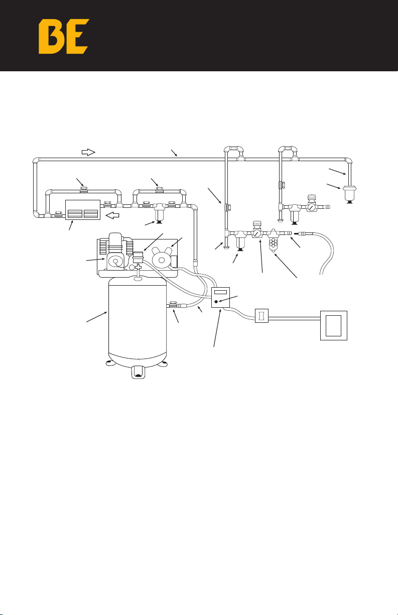
INSTALLATION DIAGRAM
This diagram is only a guide to a typical system. Consult your distributor
for detailed information regarding your particular installation.

17
start up procedure
Start Up Preparation & Procedures
The following check list shall be adhered to before putting the
compressor into operation.
1. Remove all loose pieces and tools around the compressor installation.
2. Check oil level in crankcase, add as necessary.
3. Check all pressure connections for tightness and leaks.
4. Check to make sure all safety relief valves are in place and operational.
5. Check to be sure all guards are in place and securely mounted.
6. Check fuses, circuit breakers and thermal overloads for proper size.
7. Open all manual shut-off valves (block valves) at and beyond the
compressor discharge.
8. On all 3 phase units, after all of the above conditions have been
satisfied, jog the starter switch button to check the rotational direction
of the compressor. It should agree with the rotation arrow on the
flywheel/pulley (counter clockwise, facing the shaft).
The following procedures should be followed for start-up of a new
installation, or after changes have been made to an existing installation,
and/or after service repair work has been performed.
1. Instructions in addition to those contained within this manual, supplied
by manufacturers of supporting equipment, must also be read and
understood before start-up.
2. Check oil level in crankcase.
3. Drain moisture from air receiver and traps.
4. Start compressor and watch for excessive vibration or strange noises.
If either is observed, stop the compressor immediately and correct.
5. Check air receiver or system pressure.
6. Manually activated safety relief valves by pulling ring or lever.
7. Check operation of controls.
8. After two days of operation check belt tension, air piping for leaks, and
crankcase oil level.
CAUTION
FAILURE TO PERFORM THE CHECKS MAY RESULT IN SERIOUS
INJURY OR DEATH, PROPERTY DAMAGE AND/OR MECHANICAL
FAILURE. DISCONNECT AND LOCK OUT POWER SUPPLY.

18
Stopping for Maintenance or Service
The following procedure should be followed to maximize safety when
preparing for maintenance or service.
1. Disconnect and lock-out the main power switch and hang a sign at the
switch Informing of the unit being serviced.
2. Close shut-off valve (block valve) between receiver and compressor,
or receiver and Plant air system, to prevent any back-up of air flow into
the area to be serviced.
3. Lock open manual vent valve and wait for the pressure in the area
to be serviced (compressor, receiver, etc.) to be completely relieved
before starting service. The Manual vent valve may be the drain valve in
the receiver. NEVER remove a plug to relieve the pressure.
4. Open all manual drain valves within the area to be serviced.
5. Wait for the unit to cool before starting service, (temperatures at 125
degrees F can burn the skin), some surface temperatures exceed 400
degrees F when the compressor is working).
6. Clean up all oils spills immediately to prevent slipping.
stopping procedure
CAUTION
Never assume the compressor is ready for maintenance or service
because it is stopped. The automatic stop-start control may start the
compressor at any time!

19
ALWAYS MAKE SURE POWER IS OFF BEFORE WIRING COMPRESSOR
Punch out hole in starter box for power inlet.
Place power
line 1 under
set screw
Place power
line 2 under
set screw
Place power
line 3 under
set screw
Remove Starter
lid cover
Place ground wire
under washer
Check all fitting to make sure that they are tight and place
cover back on starter box before checking for correct rota-
tion. If rotation is incorrect swap line 1 and line 3 to reverse
rotation
1
2
3
4
3 Phase Piston Compressor Wiring Diagram
Compressed Air Systems, LLC 1-800-531-9656 Fax 972-352-6364 www.compressed-air-systems.com
7.5, 10, 15 HP Electric Reciprocating Compressor
ALWAYS MAKE SURE POWER IS OFF
BEFORE WIRING COMPRESSOR
4Check all fitting to make sure that they are tight and place cover
back on box before checking for correct rotation. If rotation is
incorrect swap line 1 and line 3 to reverse rotation
compressor diagram
Remove Starter
lid cover
2Place power
line 1 under
set screw
Place ground wire under
washer
Place power
line 2 under set
screw
Place power
line 3 under
set screw
3
ALWAYS MAKE SURE POWER IS OFF BEFORE WIRING COMPRESSOR
Punch out hole in starter box for power inlet.
Place power
line 1 under
set screw
Place power
line 2 under
set screw
Place power
line 3 under
set screw
Remove Starter
lid cover
Place ground wire
under washer
Check all fitting to make sure that they are tight and place
cover back on starter box before checking for correct rota-
tion. If rotation is incorrect swap line 1 and line 3 to reverse
rotation
1
2
3
4
3 Phase Piston Compressor Wiring Diagram
Compressed Air Systems, LLC 1-800-531-9656 Fax 972-352-6364 www.compressed-air-systems.com
7.5, 10, 15 HP Electric Reciprocating Compressor
Punch out hole in starter
box for power inlet.
1
3 PHASE

20
ALWAYS MAKE SURE POWER IS OFF BEFORE WIRING COMPRESSOR
Punch out hole in starter box for power inlet.
Place 1 of the
incoming power
lines under the
starter screw
shown
Place ground
wire behind
washer for a
proper ground
Place the other
incoming power
line under the
starter screw
shown
Remove Starter
lid cover
Once the steps are complete make sure
all connections are tight and place starter
cover back on the box, before turning the
machine on.
1
2
34
1 Phase Piston Compressor Wiring Diagram
Compressed Air Systems, LLC 1-800-531-9656 Fax 972-352-6364 www.compressed-air-systems.com
7.5, 10, 15 HP Electric Reciprocating Compressor
Punch out hole in starter
box for power inlet.
1
Remove Starter
lid cover
2
Place 1 of the incoming
power lines under the
starter screw shown
Place ground wire
behind washer for a
proper ground
Place the other incoming
power line under the
starter screw shown
3
4
Once the steps are complete make sure all connections are tight and
place cover back on the box, before turning the machine on.
ALWAYS MAKE SURE POWER IS OFF
BEFORE WIRING COMPRESSOR
compressor diagram
ALWAYS MAKE SURE POWER IS OFF BEFORE WIRING COMPRESSOR
Punch out hole in starter box for power inlet.
Place 1 of the
incoming power
lines under the
starter screw
shown
Place ground
wire behind
washer for a
proper ground
Place the other
incoming power
line under the
starter screw
shown
Remove Starter
lid cover
Once the steps are complete make sure
all connections are tight and place starter
cover back on the box, before turning the
machine on.
1
2
34
1 Phase Piston Compressor Wiring Diagram
Compressed Air Systems, LLC 1-800-531-9656 Fax 972-352-6364 www.compressed-air-systems.com
7.5, 10, 15 HP Electric Reciprocating Compressor
1 PHASE
Table of contents


